
Lesson no 5 : Implement risk management frameworks to enhance project safety, reliability, and efficiency.
Effective risk management is essential to the successful delivery of mechanical engineering, manufacturing and construction projects. Every project involves uncertainties that can affect safety, quality, cost, schedule, equipment performance and overall operational outcomes. Mechanical systems may face risks associated with material defects, equipment failure, design errors, unsafe working practices, process variation, inadequate inspections, supply delays and unexpected changes in project conditions. A structured risk management framework enables organisations to identify these threats early, assess their potential impact and implement appropriate controls before they develop into major problems.
This lesson introduces Learners to the principles and practical application of risk management frameworks within QA/QC mechanical engineering environments. Risk management is not simply about responding when something goes wrong. It is a systematic and proactive process that supports informed decision-making throughout the project lifecycle. By identifying hazards and quality risks at an early stage, project teams can allocate resources effectively, establish suitable inspection and testing controls, and reduce the likelihood of costly failures.
A typical risk management framework involves several connected stages, including identifying potential risks, analysing their causes and consequences, evaluating their likelihood and severity, prioritising significant risks, implementing mitigation measures and monitoring the effectiveness of those controls. Professional tools such as risk registers, risk matrices, Failure Mode and Effects Analysis (FMEA), inspections and trend analysis can support this process.
In mechanical engineering projects, effective risk management requires cooperation between QA/QC personnel, design engineers, production teams, supervisors and project managers. Each department contributes valuable technical knowledge that helps identify weaknesses and develop realistic control measures. Clear communication is therefore essential when managing project risks.
This lesson also explores how risk management contributes to improved project safety, reliability and efficiency. Effective controls can reduce workplace incidents, prevent equipment failures, minimise defects and rework, protect project schedules and improve confidence in final project outcomes. Learners will develop an understanding of how to apply structured risk management approaches to practical mechanical engineering situations and how to review risks when project conditions, designs or operational requirements change.
By developing strong risk management capability, Learners can support a proactive quality culture in which potential problems are identified, assessed and controlled before they affect people, equipment or project performance. This approach strengthens decision-making and contributes to safer, more reliable and more efficient mechanical engineering projects.
1.Integrate Formal Risk Management Frameworks into the Existing Factory Quality Manual to Protect Both Asset Reliability and Worker Safety
A factory quality manual provides the high-level direction through which an organisation defines its commitment to quality, compliance, controlled processes and continual improvement. However, quality requirements alone may not be sufficient to manage all the uncertainties that can affect mechanical assets, production systems and workers. A formal risk management framework strengthens the quality manual by introducing a systematic method for identifying, assessing, controlling and monitoring risks throughout factory operations.
In mechanical engineering and manufacturing environments, risks are closely connected. A failure in equipment reliability may create a safety hazard, while unsafe working conditions may damage equipment or result in poor-quality output. For example, inadequate maintenance of a rotating machine can increase the risk of unexpected failure. The failure may interrupt production, damage components, expose workers to hazardous conditions and create additional inspection and repair requirements. Integrating risk management into the factory quality manual helps organisations manage such interconnected issues through a structured and consistent approach.
The purpose of this process is not to create unnecessary documentation or additional bureaucracy. It is to ensure that risk-based thinking becomes part of everyday quality management and operational decision-making. A well-integrated framework helps managers, engineers, QA/QC personnel, supervisors and workers understand how risks should be identified, escalated and controlled.
This section explains how a factory can formally integrate risk management principles into its existing quality manual while maintaining a clear focus on asset reliability, worker safety and efficient project or production performance.
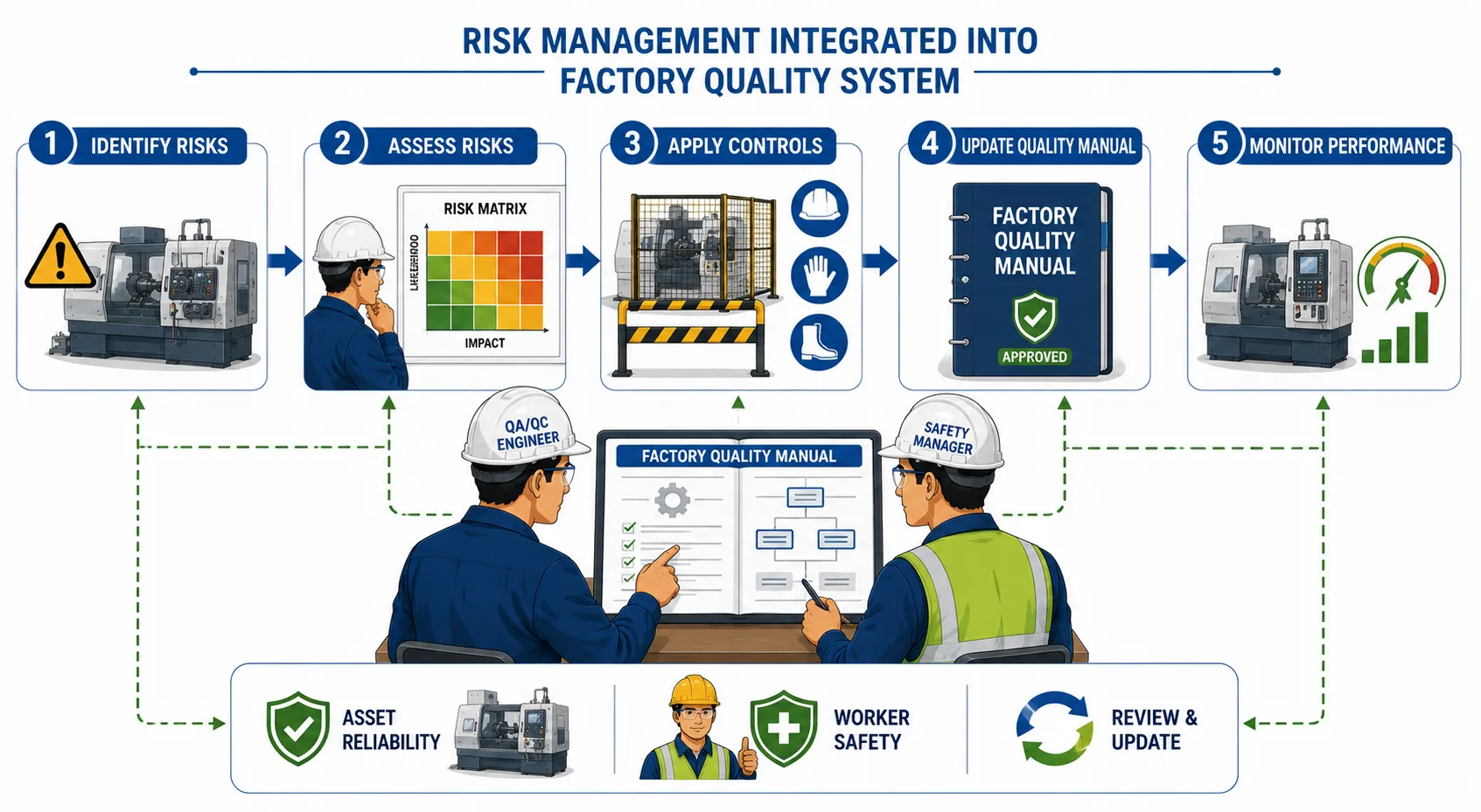
Understanding the Relationship Between Quality, Risk, Reliability and Safety
Quality, reliability and safety should not be treated as completely separate management activities. They influence one another throughout the lifecycle of mechanical equipment and manufacturing processes.
Quality management focuses on ensuring that products, processes and services meet defined requirements. Reliability focuses on the ability of equipment or systems to perform their intended function consistently over an expected period. Safety focuses on protecting workers and other affected persons from unacceptable harm.
Risk management provides the structured connection between these areas.
For example, a defect in a pressure-containing component may initially appear to be a quality issue. If the defect reduces the component’s ability to withstand operating conditions, it can become a reliability concern. If failure occurs during operation, the issue may become a serious safety risk.
An integrated framework therefore encourages the organisation to consider:
What can go wrong?
Why could it happen?
What would be affected?
How likely is the event?
How serious could the consequences be?
What controls already exist?
Are the existing controls effective?
What additional action is required?
Who is responsible for managing the risk?
How will the risk be monitored?
This approach supports proactive management rather than waiting for failures or incidents to occur.
Key Definitions and Concepts
The following table summarises important terms used when integrating risk management frameworks into a factory quality manual.
| Term | Definition | Application in a Factory Quality Manual |
|---|---|---|
| Risk | The effect of uncertainty on planned objectives or expected outcomes | Identifying events that may affect quality, safety, reliability or production |
| Hazard | A source or situation with the potential to cause harm | Identifying dangerous mechanical, chemical, electrical or operational conditions |
| Risk assessment | A structured process for evaluating likelihood and consequences | Determining the significance of equipment and process risks |
| Risk management framework | An organised system for identifying, assessing, treating and monitoring risks | Establishing consistent risk processes across factory operations |
| Asset reliability | The ability of equipment to perform its intended function consistently | Managing risks that may lead to equipment degradation or failure |
| Risk control | A measure designed to eliminate, reduce or manage a risk | Installing safeguards, increasing inspections or improving maintenance |
| Risk register | A documented record of identified risks and their management status | Tracking significant factory risks and assigned actions |
| Risk owner | The person responsible for monitoring and managing a specific risk | Assigning accountability to an appropriate manager or engineer |
| Residual risk | The level of risk remaining after controls have been applied | Reviewing whether the remaining risk is acceptable |
| Escalation | The process of referring significant risks to a higher authority | Ensuring critical risks receive appropriate management attention |
Why Formal Risk Management Should Be Included in the Quality Manual
Moving from Reactive to Proactive Management
A reactive factory often responds to problems only after equipment has failed, a defect has been discovered or an incident has occurred. This approach can result in expensive repairs, production delays and increased safety exposure.
A formal risk management framework changes the focus from reaction to prevention.
Instead of asking only:
“What went wrong?”
The organisation also asks:
“What could go wrong, and what can we do before it happens?”
Risk-based thinking encourages early action.
Key proactive activities include:
Reviewing potential failure points before production begins.
Identifying critical equipment and components.
Assessing changes in operating conditions.
Reviewing recurring defects and non-conformities.
Monitoring trends in equipment performance.
Identifying unsafe conditions before an incident occurs.
Evaluating the consequences of process changes.
This allows the quality manual to provide direction not only for controlling current work but also for anticipating future problems.
Protecting Critical Mechanical Assets
Mechanical assets represent significant organisational investments. Pumps, compressors, lifting equipment, pressure systems, production machines and other assets must perform reliably to support safe and efficient operations.
Poor reliability can result in:
Unexpected production stoppages.
Expensive emergency repairs.
Damage to connected equipment.
Reduced product quality.
Delayed project schedules.
Increased worker exposure to hazards.
A risk management framework helps identify which assets require greater attention.
Factors that may increase asset risk include:
High operating temperatures.
Heavy loads.
Continuous operation.
Corrosive environments.
Frequent vibration.
Inadequate lubrication.
Poor maintenance history.
Critical production dependency.
The quality manual should therefore require risk-based consideration when determining inspection, maintenance and monitoring priorities.
Strengthening Worker Safety
Worker safety must be integrated into operational decision-making.
A quality problem can sometimes create a direct safety hazard. For example:
A defective lifting component may fail during use.
Incorrect material selection may reduce structural integrity.
Poor welding quality may weaken a load-bearing assembly.
Inaccurate calibration may result in unsafe operating conditions.
The risk management framework should require personnel to consider both quality and safety consequences when assessing significant issues.
Selecting an Appropriate Risk Management Framework
A factory should select a framework that matches the nature, size and complexity of its operations.
The framework should provide a consistent sequence of activities.
A typical process includes:
Establish the operational context.
Identify risks and hazards.
Analyse causes and consequences.
Assess the level of risk.
Determine risk priorities.
Select appropriate controls.
Assign responsibilities.
Monitor implementation.
Review effectiveness.
Update records when conditions change.
The framework should be sufficiently structured to provide consistency but flexible enough to address different mechanical and operational situations.
Core Characteristics of an Effective Framework
An effective factory risk framework should be:
Clearly documented.
Proportionate to the level of risk.
Based on reliable evidence.
Integrated with existing quality processes.
Supported by competent personnel.
Regularly reviewed.
Linked to corrective action processes.
Connected to management decision-making.
Reviewing the Existing Factory Quality Manual
Before adding new risk management requirements, the organisation should review its existing quality manual.
The review should identify where risk management principles already exist and where improvements are required.
Areas That Should Be Reviewed
The review may include:
Quality policy.
Organisational responsibilities.
Document control.
Design and engineering controls.
Procurement procedures.
Material control.
Production processes.
Inspection and testing.
Calibration management.
Non-conformance control.
Corrective action.
Internal audits.
Management review.
Training and competence.
Each area should be examined to determine where uncertainty could affect quality, safety or reliability.
Conducting a Gap Analysis
A gap analysis compares the current quality management approach with the requirements of the proposed risk management framework.
The process may identify questions such as:
Are significant risks formally documented?
Are risk owners clearly identified?
Are safety and reliability consequences considered together?
Are process changes assessed before implementation?
Are critical risks escalated to management?
Are risk controls reviewed for effectiveness?
Is risk information communicated to relevant workers?
The results should guide the revision of the quality manual.
Establishing Risk Management Responsibilities
Clear responsibilities are essential.
Risk management should not be treated as the responsibility of only the QA/QC department.
Different personnel have different responsibilities.
Senior Management Responsibilities
Senior management should:
Approve the overall risk management policy.
Provide appropriate resources.
Review significant risks.
Support escalation decisions.
Promote risk-based thinking.
Ensure risk management supports organisational objectives.
QA/QC Management Responsibilities
QA/QC managers may:
Maintain risk management procedures.
Coordinate quality-related risk assessments.
Review recurring non-conformities.
Monitor corrective action effectiveness.
Support internal audits.
Engineering Responsibilities
Engineering personnel should:
Identify technical and design-related risks.
Assess potential equipment failure modes.
Define appropriate technical controls.
Review changes affecting mechanical integrity.
Production and Workshop Responsibilities
Supervisors and production personnel should:
Identify operational risks.
Report unsafe or abnormal conditions.
Follow approved controls.
Participate in risk assessments.
Communicate changes affecting work activities.
Individual Worker Responsibilities
Workers should:
Follow approved procedures.
Report hazards and quality concerns.
Participate in relevant risk assessments.
Avoid bypassing safety or quality controls.
Communicate abnormal equipment conditions.
Integrating Risk Identification into Factory Processes
Risk identification should be embedded into normal operations.
The quality manual can require risk reviews at key stages.
During Planning
Before starting a new operation, the team should consider:
Equipment requirements.
Material risks.
Process complexity.
Inspection requirements.
Safety hazards.
Resource availability.
During Production
During normal operations, personnel should monitor:
Process variation.
Equipment condition.
Quality trends.
Worker observations.
Near misses.
Repeated defects.
During Change
Changes can introduce new risks.
Risk assessment should therefore be triggered by:
New equipment installation.
Process modification.
Material substitution.
Design revision.
Change in operating conditions.
New production methods.
Risk Assessment Methods for Mechanical Engineering
Different risks require different assessment tools.
The quality manual should provide guidance on selecting appropriate methods.
Risk Matrix
A risk matrix commonly evaluates:
Likelihood.
Consequence.
The combined result helps determine the priority of action.
For example:
Low likelihood and low consequence may require routine monitoring.
High likelihood and severe consequence may require immediate action.
Failure Mode and Effects Analysis
FMEA provides a structured method for examining potential failure modes.
It typically considers:
Severity.
Occurrence.
Detection.
The analysis helps prioritise potential failures.
Inspection-Based Risk Assessment
Inspection data can identify developing risks.
Examples include:
Increasing vibration.
Wear measurements.
Thickness loss.
Repeated dimensional deviations.
Trend Analysis
Trend analysis examines historical information.
Useful information may include:
Equipment failures.
Non-conformities.
Repair history.
Inspection results.
Production delays.
Developing the Risk Register
A risk register provides a central record of significant risks.
The factory quality manual should define how risks are recorded and maintained.
A typical risk register may include:
Risk identification number.
Description of the risk.
Source or cause.
Potential consequences.
Likelihood rating.
Consequence rating.
Existing controls.
Residual risk.
Required actions.
Risk owner.
Target completion date.
Review status.
The register should remain current.
It should not become a document that is completed once and then ignored.
Establishing Risk Control Measures
After risks have been assessed, appropriate controls must be selected.
The control should match the nature and seriousness of the risk.
Possible controls include:
Eliminating the hazardous activity.
Substituting a safer process.
Modifying equipment design.
Installing physical safeguards.
Increasing inspection frequency.
Introducing preventive maintenance.
Improving procedures.
Providing additional training.
Using monitoring systems.
Multiple controls may be required for significant risks.
Reliability-Focused Controls
Controls designed to improve asset reliability may include:
Condition monitoring.
Preventive maintenance.
Predictive maintenance.
Lubrication control.
Alignment verification.
Vibration monitoring.
Scheduled inspections.
Safety-Focused Controls
Safety-related controls may include:
Machine guarding.
Emergency stop systems.
Lockout procedures.
Restricted access.
Safe work instructions.
Competence requirements.
Integrating Risk Management into Existing Quality Procedures
Risk management should connect with existing procedures rather than operate separately.
Integration with Inspection and Test Plans
Risk level can influence inspection requirements.
Higher-risk equipment or processes may require:
Additional inspection points.
Increased testing.
Independent verification.
Enhanced documentation.
Integration with Non-Conformance Control
Non-conformities can provide valuable risk information.
The quality manual should require significant non-conformities to be reviewed for:
Potential safety consequences.
Reliability implications.
Recurrence risk.
Integration with Corrective Action
Corrective actions should address causes rather than symptoms.
Risk assessment can help determine whether:
Immediate action is sufficient.
Wider controls are required.
Similar processes should be reviewed.
Integration with Internal Audits
Audits should assess whether:
Risk assessments are current.
Controls are implemented.
Responsibilities are understood.
Records are maintained.
Controls are effective.
Practical Example: Critical Pump Reliability Risk
Consider a factory that operates a pump supporting a critical production process.
Maintenance records show increasing vibration levels.
A risk review identifies:
Potential bearing failure.
Possible unplanned shutdown.
Damage to connected equipment.
Potential worker exposure during emergency repairs.
The risk management process may involve:
Recording the risk.
Assessing potential consequences.
Reviewing existing monitoring controls.
Increasing vibration monitoring.
Planning preventive maintenance.
Keeping appropriate spare components available.
Reviewing the effectiveness of the controls.
The quality manual should define how such reliability risks are identified, assessed and escalated.
Practical Example: Safety and Quality Risk in a Manufacturing Process
A manufacturing process produces heavy mechanical assemblies.
Workers report that components occasionally move unexpectedly during positioning.
The issue creates:
A worker safety concern.
A risk of component damage.
A risk of dimensional misalignment.
The team conducts a risk assessment.
Controls may include:
Reviewing the handling method.
Improving positioning fixtures.
Verifying lifting equipment.
Updating work instructions.
Providing additional training.
This example demonstrates why quality and safety risks should be managed together.
Communicating Risk Information
Risk controls are ineffective if workers do not understand them.
The quality manual should establish communication methods.
These may include:
Tool-box talks.
Safety and quality briefings.
Shift meetings.
Updated procedures.
Training sessions.
Visual workplace instructions.
Communication should be appropriate to the workforce.
Complex risk information should be translated into clear operational instructions.
Training and Competence Requirements
Personnel responsible for risk management must understand their roles.
Training may cover:
Basic risk concepts.
Hazard identification.
Risk assessment methods.
Risk registers.
Reporting requirements.
Escalation procedures.
Control verification.
Competence should reflect the level of responsibility.
Personnel performing complex technical assessments may require specialised engineering knowledge.
Monitoring and Reviewing Risk Controls
Implementing a control does not guarantee that it is effective.
The organisation should monitor performance.
Review activities may include:
Inspections.
Internal audits.
Performance trend analysis.
Equipment monitoring.
Incident reviews.
Worker feedback.
Questions should include:
Is the control being followed?
Has the risk level changed?
Has a new risk emerged?
Is the control producing the expected result?
Managing Change Through Risk Assessment
Factories are dynamic environments.
Changes may affect established risk controls.
The quality manual should require formal risk review when significant changes occur.
Examples include:
New machinery.
Modified production processes.
Different materials.
Increased production capacity.
Changes to maintenance methods.
Revised engineering specifications.
A change should not be considered fully implemented until relevant risks have been assessed and appropriate controls established.
Escalating Critical Risks
Some risks cannot be managed effectively at workshop level.
The quality manual should establish escalation criteria.
Risks may require escalation when they involve:
Serious potential injury.
Significant asset damage.
Major production interruption.
Critical quality failure.
Regulatory implications.
Escalation ensures that decision-makers receive appropriate information.
Key Benefits of Integrating Risk Management into the Quality Manual
A formal integrated approach can provide several benefits.
Improved Asset Reliability
Risk-based controls help organisations focus attention on critical equipment.
Enhanced Worker Safety
Potential hazards can be identified before they lead to incidents.
Better Resource Allocation
Higher-risk activities can receive appropriate inspection and maintenance resources.
Reduced Rework and Downtime
Early identification can prevent significant failures.
Improved Decision-Making
Managers can make decisions using structured evidence.
Stronger Quality Culture
Workers develop greater awareness of potential problems and preventive actions.
Common Challenges and How to Address Them
Challenge: Risk Management Becomes Excessive Paperwork
A system can become ineffective if forms are completed without meaningful analysis.
Good practice includes:
Using proportionate assessments.
Focusing on significant risks.
Simplifying routine processes.
Using practical workplace evidence.
Challenge: Risks Are Identified but Not Controlled
Recording a risk is only the beginning.
Organisations should:
Assign clear owners.
Establish deadlines.
Monitor action completion.
Verify effectiveness.
Challenge: Safety and Quality Departments Work Separately
Separate systems can create gaps.
Good integration requires:
Shared information.
Coordinated reviews.
Common escalation processes.
Joint learning.
Recommended Procedure for Updating the Factory Quality Manual
A structured implementation process may follow these stages.
Stage 1: Review the Existing Manual
Identify current procedures and risk-related gaps.
Stage 2: Define the Risk Management Policy
Establish organisational commitment and objectives.
Stage 3: Develop the Framework
Define identification, assessment, treatment and monitoring processes.
Stage 4: Assign Responsibilities
Identify risk owners and approval authorities.
Stage 5: Integrate with Existing Procedures
Connect risk requirements to quality, maintenance and safety activities.
Stage 6: Train Personnel
Ensure relevant personnel understand their responsibilities.
Stage 7: Implement and Monitor
Apply the framework during normal factory operations.
Stage 8: Audit Effectiveness
Verify implementation and identify improvement opportunities.
Stage 9: Review and Improve
Update the manual when operational conditions or risks change.
Best Practice Checklist
When integrating formal risk management into a factory quality manual, the organisation should ensure that:
A clear risk management policy is established.
Risk responsibilities are assigned.
Significant risks are formally recorded.
Asset reliability and worker safety are considered together.
Appropriate assessment methods are used.
Risk controls are proportionate.
Significant changes trigger risk review.
Risk information is communicated effectively.
Controls are monitored for effectiveness.
Critical risks are escalated appropriately.
The framework is regularly audited and improved.
Conclusion
Integrating formal risk management frameworks into an existing factory quality manual provides a structured approach for protecting mechanical assets, workers and operational performance. The framework enables organisations to identify potential failures and hazards before they develop into serious quality, reliability or safety problems.
Effective integration requires more than adding a new section to the quality manual. Risk management must be connected to planning, engineering, production, inspection, maintenance, non-conformance control and continual improvement. Responsibilities must be clear, risk assessments must be proportionate and controls must be monitored to confirm that they remain effective.
In mechanical engineering environments, asset reliability and worker safety are closely linked. A structured risk framework helps organisations understand these relationships and make informed decisions about where resources and controls are most needed.
By embedding risk-based thinking into the factory quality management system, organisations can move from reactive problem-solving towards proactive prevention. This supports safer workplaces, more reliable equipment, reduced downtime, improved quality performance and greater operational efficiency. Ultimately, a well-maintained and continuously improved risk management framework becomes an essential part of achieving sustainable operational excellence.
2.Monitor Live Manufacturing Data Against Risk Indicators to Catch and Correct Safety or Efficiency Drops Before They Cause Process Failures
Modern mechanical manufacturing environments generate significant amounts of operational information. Production equipment, sensors, inspection systems, maintenance records and digital control systems can provide continuous or near-real-time data about the condition and performance of machines and processes. However, collecting data alone does not improve safety, reliability or efficiency. The real value is achieved when organisations monitor relevant live manufacturing data against clearly defined risk indicators and use the results to take timely corrective action.
A sudden increase in machine temperature, vibration, energy consumption, rejection rates or cycle time may indicate that a process is moving away from its normal operating condition. If such changes are identified early, the organisation may be able to investigate and correct the problem before it develops into equipment failure, a safety incident, excessive waste or significant production downtime.
This approach is particularly important within mechanical engineering and QA/QC environments because process failures are often preceded by smaller warning signs. A bearing may begin to generate increased vibration before failing completely. A cutting tool may gradually wear and produce increasing dimensional variation. A production line may experience longer cycle times before suffering a major mechanical breakdown. Monitoring these indicators enables project and factory teams to move from reactive response towards proactive risk control.
The purpose of live data monitoring is therefore to detect abnormal conditions, compare performance against established risk thresholds, investigate significant deviations and implement proportionate corrective actions. This process supports worker safety, asset reliability, product quality and operational efficiency.
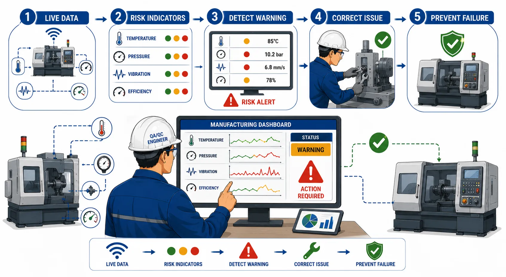
Understanding Live Manufacturing Data
Live manufacturing data refers to information collected from operational activities while equipment and processes are running or at regular intervals close to the time of operation. Depending on the level of digitalisation, data may be obtained automatically from sensors and control systems or entered manually by operators and inspectors.
Common sources of live manufacturing data include:
Temperature sensors.
Pressure gauges and transmitters.
Vibration monitoring devices.
Speed and rotational sensors.
Energy consumption meters.
Production counters.
Cycle-time monitoring systems.
Automated inspection equipment.
Dimensional measurement systems.
Machine alarms.
Operator observations.
Quality inspection records.
Live data provides an indication of what is happening within the manufacturing process at a particular time. However, individual data values should not always be interpreted in isolation. Effective risk monitoring requires organisations to examine trends, compare results against expected operating ranges and consider the technical context.
For example, a small temporary increase in temperature may not necessarily indicate a serious problem. However, a continuous upward trend that approaches an established limit may indicate developing friction, inadequate cooling or another mechanical issue.
The Difference Between Data and Risk Information
Raw data becomes useful risk information when it is compared against an established reference point.
A temperature value of 85°C has limited meaning without knowing:
The normal operating temperature.
The equipment manufacturer’s specified limits.
The acceptable process range.
The trend over time.
The relationship between temperature and other indicators.
Risk indicators provide this context.
A risk indicator is a measurable condition, trend or event that may signal an increased likelihood of an unwanted outcome. The indicator helps the organisation identify when additional investigation or action may be required.
Examples of risk indicators include:
Increasing machine vibration.
Repeated high-temperature alarms.
Rising product rejection rates.
Increased equipment downtime.
Declining production efficiency.
Repeated quality deviations.
Increasing maintenance interventions.
Abnormal energy consumption.
Repeated safety observations.
Key Definitions and Concepts
| Term | Definition | Application in Manufacturing Risk Management |
|---|---|---|
| Live manufacturing data | Current or near-real-time information generated during manufacturing operations | Monitoring machine temperature, pressure, vibration and production output |
| Risk indicator | A measurable signal that may show increasing exposure to a risk | Rising vibration indicating potential bearing deterioration |
| Leading indicator | A measure that provides early warning before a significant failure or incident occurs | Increasing vibration trend before machine breakdown |
| Lagging indicator | A measure that records an event after it has occurred | Number of equipment failures during a month |
| Threshold | A defined value or condition that triggers review or action | A vibration level requiring engineering investigation |
| Control limit | A defined boundary used to identify unusual process variation | Identifying when process measurements require investigation |
| Trend analysis | Examination of data changes over time | Monitoring gradual increases in rejection rates |
| Deviation | A departure from an expected requirement or operating condition | Pressure operating outside the approved range |
| Corrective action | Action taken to address the cause of an identified problem | Replacing a damaged component causing abnormal vibration |
| Predictive monitoring | Using condition data to anticipate possible failures | Monitoring equipment condition before breakdown occurs |
The Importance of Monitoring Data Against Risk Indicators
Early Detection of Process Deterioration
Mechanical equipment rarely fails without any warning. In many cases, changes occur gradually before a significant failure develops.
Early warning signs may include:
Increasing vibration.
Higher operating temperatures.
Reduced production speed.
Increasing power consumption.
Unusual noise.
Frequent alarms.
Declining dimensional accuracy.
Monitoring these indicators enables the organisation to investigate problems while there is still time to take controlled action.
For example, if a rotating machine begins to show increasing vibration, the maintenance team may inspect alignment, bearings or balancing before the equipment experiences catastrophic failure.
Protecting Worker Safety
Live data monitoring can also support safety management.
Abnormal operating conditions may indicate developing hazards.
Examples include:
Excessive pressure.
Rising temperatures.
Unusual equipment movement.
Increased vibration.
Repeated machine safety trips.
If a risk indicator reaches a defined critical level, immediate action may be required.
The objective is not simply to collect safety data but to use information to prevent harm.
Maintaining Production Efficiency
Efficiency can decline gradually.
A manufacturing process may continue operating while experiencing:
Longer cycle times.
Increased energy consumption.
Frequent minor stoppages.
Higher scrap rates.
These changes may not initially stop production but can significantly reduce overall performance.
Risk-based monitoring enables supervisors to identify efficiency losses before they become major operational failures.
Establishing Relevant Risk Indicators
Not every available data point should automatically become a risk indicator. Excessive monitoring can create information overload and make it difficult to identify genuinely important conditions.
Risk indicators should be selected based on the factory’s operations and significant risks.
Identify Critical Assets and Processes
The first stage is to identify equipment and processes where failure could have significant consequences.
Criticality may depend on:
Safety consequences.
Production dependency.
Equipment replacement cost.
Potential quality impact.
Environmental conditions.
Availability of backup equipment.
High-criticality assets generally require closer monitoring.
Identify Potential Failure Modes
The organisation should consider how the asset or process could fail.
For a rotating machine, potential failure modes may include:
Bearing deterioration.
Shaft misalignment.
Excessive vibration.
Lubrication failure.
Overheating.
Relevant indicators can then be selected to detect these developing conditions.
Define Measurable Indicators
Indicators should be:
Relevant.
Measurable.
Understandable.
Reliable.
Linked to action.
Examples include:
Vibration level.
Operating temperature.
Pressure variation.
Cycle time.
Defect rate.
Equipment availability.
Establishing Normal Operating Conditions
Risk monitoring requires a clear understanding of what normal performance looks like.
The organisation should establish reference values using appropriate evidence.
Possible sources include:
Equipment manufacturer guidance.
Engineering specifications.
Historical performance data.
Approved operating procedures.
Inspection records.
Commissioning results.
Normal conditions may vary depending on:
Production load.
Environmental temperature.
Material type.
Equipment age.
Operating speed.
Therefore, thresholds should not be selected arbitrarily.
Setting Risk Thresholds and Action Levels
Risk indicators become more useful when clear action levels are established.
A practical monitoring framework may use several levels.
Normal Condition
The process is operating within expected limits.
Required action may include:
Continue routine monitoring.
Maintain normal inspection frequency.
Caution Level
The indicator shows an unusual trend or approaches a defined limit.
Required action may include:
Increase monitoring.
Inform the responsible supervisor.
Review related indicators.
Plan further inspection.
Warning Level
The indicator exceeds an established warning threshold.
Required action may include:
Conduct technical investigation.
Identify potential causes.
Implement temporary controls.
Review operational conditions.
Critical Level
The condition presents an unacceptable risk.
Required action may include:
Stop the affected process where required.
Make the equipment safe.
Escalate to authorised personnel.
Conduct a formal investigation.
Approve corrective action before restart.
The quality and risk management framework should clearly define who has authority to make decisions at each level.
A Step-by-Step Live Risk Monitoring Process
Step 1: Identify the Process or Asset
Determine what is being monitored.
Examples include:
CNC machining equipment.
Pumps.
Compressors.
Welding systems.
Material handling equipment.
Assembly lines.
The importance of the equipment should be considered.
Step 2: Review Associated Risks
Identify potential consequences.
Questions may include:
Could failure injure a worker?
Could the failure stop production?
Could it cause product defects?
Could it damage connected equipment?
Step 3: Select Relevant Data Sources
Determine where information will come from.
Possible sources include:
Automated sensors.
Machine control systems.
Inspection instruments.
Operator records.
Step 4: Establish Baselines
Define expected normal performance.
The baseline should be based on credible technical information.
Step 5: Set Thresholds
Establish conditions that require:
Monitoring.
Investigation.
Corrective action.
Escalation.
Step 6: Monitor the Data
Review information at an appropriate frequency.
Monitoring frequency should reflect the level of risk.
Step 7: Identify Deviations
Compare actual performance against:
Baselines.
Thresholds.
Historical trends.
Step 8: Investigate the Cause
A deviation should not automatically be assumed to have one specific cause.
The investigation should examine:
Equipment condition.
Material changes.
Operating conditions.
Recent maintenance.
Process adjustments.
Step 9: Implement Corrective Action
The response should address the identified cause.
Possible actions include:
Adjusting process settings.
Replacing a component.
Performing maintenance.
Increasing inspections.
Temporarily reducing production speed.
Step 10: Verify Effectiveness
After action is taken, monitoring should confirm whether:
The indicator has returned to an acceptable range.
The underlying cause has been addressed.
Additional controls are required.
Using Leading and Lagging Indicators
Leading Indicators
Leading indicators provide information before a major event occurs.
Examples include:
Increased vibration.
Increasing inspection failures.
Overdue maintenance tasks.
Rising equipment temperature.
Repeated minor alarms.
These indicators are valuable because they support prevention.
Lagging Indicators
Lagging indicators record results after an event.
Examples include:
Equipment breakdowns.
Lost production hours.
Reported injuries.
Number of rejected components.
Lagging indicators remain useful for reviewing historical performance but cannot prevent an event that has already occurred.
A strong risk monitoring system should use both.
Monitoring Safety Indicators
Safety monitoring should focus on meaningful signals.
Relevant indicators may include:
Repeated safety alarms.
Equipment guard failures.
Emergency stop activations.
Abnormal pressure readings.
Excessive temperatures.
Near-miss reports.
Workers should also be encouraged to report abnormal conditions that may not yet appear in automated data.
Human observation remains an important source of risk information.
Monitoring Efficiency Indicators
Efficiency indicators help identify declining operational performance.
Examples include:
Cycle time.
Equipment availability.
Production rate.
Energy consumption.
Minor stoppages.
Rework levels.
A gradual decline should not be ignored simply because production continues.
Small losses can develop into major failures.
Monitoring Quality Indicators
Quality data can reveal emerging process risks.
Relevant indicators include:
Dimensional variation.
Rejection rates.
Rework levels.
Inspection failures.
Process capability trends.
Repeated deviations may indicate that a process is losing stability.
Practical Example: Detecting Bearing Failure
A production machine operates continuously.
Live monitoring shows a gradual increase in vibration.
The system indicates:
Normal range during the previous month.
Small increase during the current week.
Continued upward trend.
The vibration has not yet reached the critical limit.
The maintenance and QA/QC teams review the data.
They:
Verify sensor accuracy.
Inspect lubrication condition.
Review maintenance history.
Schedule equipment inspection.
The inspection identifies early bearing deterioration.
The bearing is replaced during planned maintenance.
This prevents:
Unexpected machine failure.
Production downtime.
Possible secondary equipment damage.
The example demonstrates the value of acting on a trend before critical failure occurs.
Practical Example: Efficiency Drop in a Machining Process
A machining process begins to show longer cycle times.
Production output remains acceptable, but monitoring shows a gradual decline in efficiency.
The team investigates.
Potential causes include:
Tool wear.
Machine calibration issues.
Material variation.
Incorrect process settings.
The investigation confirms that cutting tools are reaching the end of their effective operating life earlier than expected.
The organisation revises the tool monitoring process and establishes an earlier replacement threshold.
The result is:
More consistent cycle times.
Reduced product variation.
Lower risk of unexpected process interruption.
Integrating Live Monitoring with the Risk Register
Live data monitoring should connect with the wider risk management system.
When a significant indicator reveals an emerging risk, the organisation may need to update the risk register.
The record may include:
Description of the emerging risk.
Relevant data trend.
Potential consequences.
Current risk level.
Required actions.
Responsible person.
This ensures that important risks are managed systematically rather than being addressed informally.
The Role of Digital Manufacturing Systems
Digital systems can improve monitoring capability.
Examples include:
Industrial sensors.
Manufacturing execution systems.
Computerised maintenance systems.
Automated dashboards.
Data historians.
These systems can help teams:
Collect data consistently.
Display trends.
Generate alerts.
Support investigation.
However, technology does not replace professional judgement.
Personnel must understand:
What the data means.
Whether the data is reliable.
What actions are appropriate.
Avoiding Data Overload
Collecting excessive information can reduce effectiveness.
A useful monitoring system should focus on indicators that support decisions.
Good practice includes:
Selecting critical indicators.
Using clear dashboards.
Highlighting abnormal trends.
Defining action responsibilities.
The objective is not to monitor everything but to monitor what matters.
Data Accuracy and Reliability
Incorrect data can lead to incorrect decisions.
The organisation should consider:
Sensor calibration.
Instrument condition.
Data entry accuracy.
System reliability.
Missing information.
Where a reading appears unusual, it may be necessary to verify the measurement before making major decisions.
Responding to Deviations
Not every deviation requires the same response.
The response should reflect the level of risk.
A proportionate approach may involve:
Routine monitoring for minor variation.
Increased inspection for developing trends.
Technical investigation for significant deviations.
Immediate control measures for critical conditions.
Clear escalation procedures should prevent delays when serious risks are identified.
Root Cause Analysis
Correcting the visible symptom may not prevent recurrence.
For example, resetting a machine alarm without investigating why it occurred may allow the underlying problem to continue.
Root cause analysis may examine:
Equipment condition.
Human factors.
Procedure weaknesses.
Material issues.
Environmental conditions.
The depth of analysis should be proportionate to the seriousness of the problem.
Roles and Responsibilities
Operators
Operators may:
Observe equipment performance.
Report abnormal conditions.
Follow response procedures.
Record relevant observations.
Supervisors
Supervisors may:
Review trends.
Coordinate initial responses.
Escalate significant issues.
QA/QC Personnel
QA/QC personnel may:
Review quality indicators.
Identify process trends.
Support investigations.
Maintenance Personnel
Maintenance teams may:
Analyse equipment condition.
Perform inspections.
Implement technical corrective actions.
Management
Management should:
Review significant risks.
Allocate resources.
Support critical decisions.
Key Benefits of Live Risk Monitoring
Improved Safety
Early identification of abnormal conditions can prevent dangerous failures.
Increased Reliability
Condition trends can support planned maintenance.
Reduced Downtime
Problems can be corrected before major breakdowns occur.
Improved Quality
Process variation can be identified early.
Better Efficiency
Gradual performance losses can be investigated.
Stronger Decision-Making
Teams can use evidence rather than assumptions.
Common Challenges
Challenge: Delayed Response to Alerts
An alarm is ineffective if no one responds.
Good practice includes:
Assigning responsibilities.
Defining response times.
Escalating unresolved issues.
Challenge: Incorrect Thresholds
Poorly selected limits can create unnecessary alarms or fail to identify real risks.
Thresholds should be based on:
Technical requirements.
Historical evidence.
Equipment guidance.
Challenge: Ignoring Trends
A single reading may appear acceptable while the overall trend indicates deterioration.
Teams should examine:
Direction of change.
Rate of change.
Related indicators.
Challenge: Treating Every Alarm as a Major Emergency
Overreaction can create alarm fatigue.
Responses should be proportionate.
Best Practice Principles
Effective live manufacturing risk monitoring should:
Focus on significant risks.
Use reliable data.
Establish meaningful baselines.
Define clear thresholds.
Monitor trends.
Assign response responsibilities.
Investigate significant deviations.
Verify corrective actions.
Update risk assessments when required.
Building a Continuous Monitoring Culture
Effective monitoring is not only a technical activity.
It requires a culture in which workers understand the importance of early reporting.
Organisations should encourage personnel to:
Report unusual conditions.
Ask questions when readings are unclear.
Follow escalation procedures.
Participate in investigations.
Learn from recurring trends.
This supports proactive risk management.
Conclusion
Monitoring live manufacturing data against risk indicators is a powerful method for protecting worker safety, improving asset reliability and maintaining operational efficiency. Mechanical and manufacturing processes often provide early warning signs before significant failures occur. By identifying these signs through structured monitoring, organisations can take corrective action before a minor deviation develops into a major process failure.
An effective monitoring system begins by identifying critical assets and processes, understanding their associated risks and selecting meaningful indicators. Reliable baselines and proportionate thresholds help personnel distinguish between normal variation and conditions requiring investigation or intervention.
Live monitoring should examine safety, quality and efficiency together because these areas are closely connected. Rising vibration may indicate a reliability problem, while increasing process variation may signal a developing quality failure. Both may eventually affect worker safety and production performance.
The most effective systems combine technology with professional judgement. Digital sensors and dashboards can provide rapid information, but competent personnel are required to interpret trends, investigate causes and make appropriate decisions.
By integrating live data monitoring with risk registers, maintenance processes, inspections and corrective action systems, organisations can create a proactive framework for managing operational uncertainty. This approach helps prevent failures, reduce downtime, improve efficiency and support safer, more reliable mechanical engineering operations.
3.Redesign High-Risk Mechanical Testing Operations to Reduce Human Error and Eliminate Unnecessary Physical Handling Risks
High-risk mechanical testing operations are essential for verifying the safety, reliability, performance and conformity of mechanical components, equipment and manufactured products. These operations may involve pressure testing, load testing, destructive testing, non-destructive testing (NDT), hardness testing, tensile testing, dimensional verification, rotating equipment tests and other specialised inspection activities. While testing is necessary to confirm that products and systems meet specified requirements, the testing process itself can create significant risks for personnel and equipment.
A poorly designed testing operation may expose workers to unnecessary manual handling, repetitive movements, heavy lifting, pinch points, stored energy, high pressure, moving machinery, sharp edges or unexpected equipment failure. In addition, complex or poorly controlled testing procedures can increase the likelihood of human error. An incorrect test setup, inaccurate instrument selection, improper sample identification or failure to follow the correct sequence may compromise both safety and the reliability of test results.
Redesigning high-risk mechanical testing operations involves systematically reviewing how work is currently performed and identifying opportunities to remove hazards, simplify activities, reduce physical handling and introduce more reliable controls. The objective is not simply to make testing faster. The primary objective is to create a safer, more consistent and more reliable testing process in which unnecessary risks are eliminated or reduced at their source.
A strong redesign process considers the interaction between people, equipment, materials, procedures and the working environment. It uses risk assessment, human factors principles, engineering controls, automation and clear operating procedures to improve the overall testing system.
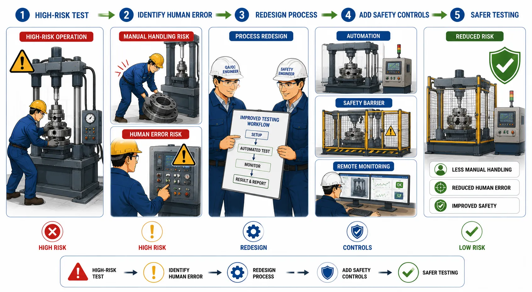
The Purpose of Redesigning High-Risk Testing Operations
Mechanical testing should be designed so that personnel can complete required activities safely and consistently. Where an existing operation depends heavily on individual memory, excessive manual effort or repeated physical handling, the process may be vulnerable to error and injury.
The redesign of testing operations aims to achieve the following outcomes:
Reduce the likelihood of human error.
Eliminate unnecessary manual handling.
Minimise exposure to hazardous energy.
Improve the consistency of test setups.
Reduce unnecessary process complexity.
Improve the reliability of test results.
Reduce worker fatigue.
Improve traceability and documentation.
Support compliance with approved safety and quality requirements.
Increase confidence in mechanical testing activities.
The most effective redesigns address the underlying causes of risk rather than simply instructing workers to be more careful.
For example, if a technician must manually lift a heavy mechanical component onto a test rig several times each day, the preferred solution is not simply to provide repeated reminders about safe lifting. A better solution may involve redesigning the work area, installing a lifting aid, using a positioning fixture or changing the testing sequence to remove unnecessary handling.
Understanding High-Risk Mechanical Testing Operations
High-risk testing operations are activities in which failure, incorrect execution or uncontrolled exposure could result in injury, equipment damage, inaccurate results or significant operational disruption.
The level of risk depends on several factors, including:
The type of mechanical equipment being tested.
The amount of stored energy involved.
The weight and size of test items.
The use of pressure, force or high-speed movement.
The complexity of the testing procedure.
The level of manual intervention required.
The competence and workload of personnel.
The condition of testing equipment.
The working environment.
Common High-Risk Mechanical Testing Activities
Examples of higher-risk activities may include:
Hydrostatic pressure testing.
Pneumatic pressure testing.
Mechanical load testing.
Proof-load testing.
Tensile and compression testing.
Rotating equipment testing.
Fatigue testing.
Impact testing.
Destructive testing.
Testing of large or heavy mechanical assemblies.
Testing involving suspended loads.
High-temperature testing.
Each operation should be assessed according to its specific hazards and testing requirements.
Sources of Human Error During Testing
Human error may occur at any stage of the testing process.
Common sources include:
Selecting the wrong test procedure.
Using an incorrect instrument.
Entering incorrect test parameters.
Misidentifying the test sample.
Recording incorrect results.
Skipping a procedural step.
Misinterpreting an acceptance criterion.
Failing to verify equipment condition.
Working while fatigued.
Being distracted during a critical activity.
Human error should not automatically be treated as an individual failure. In many cases, errors occur because the system has been poorly designed.
A process that requires a technician to remember numerous complex steps without clear guidance is more vulnerable to error than a process that uses structured checklists, automated controls and clear visual information.
Key Definitions and Concepts
| Term | Definition | Application in High-Risk Mechanical Testing |
|---|---|---|
| Human error | An unintended action, decision or omission that produces an incorrect outcome | Entering an incorrect pressure value into a testing system |
| Human factors | The study of how people interact with tasks, equipment, information and working environments | Designing a test station to reduce confusion and fatigue |
| Manual handling | The lifting, lowering, pushing, pulling, carrying or moving of loads by physical effort | Moving heavy test specimens onto a test rig |
| Engineering control | A physical or technical measure designed to reduce exposure to hazards | Installing a mechanical lifting device or protective test enclosure |
| Automation | The use of technology to perform or control activities with reduced manual intervention | Automatic pressure monitoring and data recording |
| Standardisation | Establishing a consistent method for performing an activity | Using the same approved setup process for each test |
| Fail-safe design | Designing equipment so that failure results in a safe condition | Automatic shutdown when a pressure limit is exceeded |
| Interlock | A control that prevents unsafe operation unless defined conditions are met | Preventing a test from starting until a protective guard is closed |
| Ergonomics | Designing work to fit human capabilities and limitations | Adjusting test bench height to reduce awkward postures |
| Residual risk | The level of risk remaining after controls have been applied | Remaining hazards after lifting aids and barriers are introduced |
Applying the Hierarchy of Controls to Testing Operations
When redesigning a high-risk testing activity, organisations should apply a structured approach to risk reduction. Controls should focus on eliminating hazards where reasonably practicable rather than relying primarily on worker behaviour.
Elimination
Elimination involves removing the hazard completely.
Examples may include:
Removing an unnecessary manual handling stage.
Eliminating repeated movement of heavy test specimens.
Removing unnecessary testing steps.
Relocating hazardous preparation work to a safer controlled area.
The most effective redesign questions whether a particular activity needs to occur at all.
Substitution
Where elimination is not possible, the organisation may replace a hazardous method with a safer alternative.
Examples include:
Using a lower-risk testing method where technically appropriate.
Replacing manual measurements with automated measurement systems.
Using safer fixtures instead of unstable temporary supports.
Engineering Controls
Engineering controls reduce risk through physical design.
Examples include:
Mechanical lifting devices.
Automated clamping systems.
Protective barriers.
Remote monitoring.
Pressure relief systems.
Safety interlocks.
Fixed test fixtures.
Administrative Controls
Administrative controls include procedures and management arrangements.
Examples include:
Approved testing procedures.
Competency requirements.
Pre-test checklists.
Restricted access.
Clear test planning.
Personal Protective Equipment
Personal protective equipment may provide additional protection where residual risks remain.
However, PPE should not be treated as the primary solution when hazards can be reduced through redesign.
Conducting a Detailed Review of the Existing Testing Process
Before redesigning an operation, the organisation must understand how the work is currently performed.
A useful review should examine the complete process from preparation through completion.
Map the Current Workflow
The team should document each stage.
A typical workflow may include:
Receive the test request.
Identify the component.
Review the test specification.
Move the item to the test area.
Prepare the equipment.
Install the specimen.
Connect instruments.
Perform the test.
Record the results.
Remove the specimen.
Prepare the equipment for the next activity.
Each stage should be examined for:
Hazards.
Manual handling.
Repeated movements.
Potential mistakes.
Delays.
Unnecessary complexity.
Observe the Actual Work
Written procedures may not always reflect actual practice.
The review should consider how technicians perform the activity in real working conditions.
Observation may identify:
Informal workarounds.
Awkward postures.
Repeated lifting.
Difficult-to-read displays.
Poor equipment positioning.
Confusing controls.
The people who perform the testing activity should be involved in the review because they often have direct knowledge of practical problems.
Identifying Unnecessary Physical Handling
Physical handling is a major source of risk in mechanical testing, particularly where components are heavy, irregularly shaped or frequently repositioned.
The redesign process should identify every occasion on which a person:
Lifts a component.
Carries equipment.
Pushes a heavy trolley.
Repositions a test specimen.
Reaches across equipment.
Works in an awkward posture.
The key question should be:
Can this physical movement be eliminated or reduced through better process design?
Reducing Repeated Lifting
Repeated lifting can cause fatigue and increase the likelihood of injury.
Potential redesign measures include:
Installing overhead lifting systems.
Using mechanical hoists.
Providing adjustable-height tables.
Introducing roller systems.
Using purpose-designed transport fixtures.
Improving Component Positioning
Poor positioning can require workers to make repeated adjustments.
A dedicated fixture can:
Hold the component securely.
Maintain correct alignment.
Reduce manual adjustment.
Improve repeatability.
Designing for Human Reliability
Human reliability improves when the testing system makes the correct action easier and the incorrect action more difficult.
Simplify Complex Procedures
Long and complicated procedures increase cognitive demand.
The redesign process should:
Remove unnecessary steps.
Group related activities.
Use logical sequences.
Present information clearly.
Critical instructions should be easy to identify.
Use Standardised Test Setups
Variation between technicians can create inconsistent results.
Standardisation may include:
Approved fixtures.
Defined instrument positions.
Standard connection arrangements.
Consistent control settings.
Introduce Error-Proofing
Error-proofing reduces the likelihood of predictable mistakes.
Examples include:
Connectors that fit only the correct location.
Barcode identification.
Automated parameter checks.
System warnings.
Interlocks.
Using Automation to Reduce Risk and Error
Automation can reduce exposure to hazardous conditions and improve data consistency.
Automated Data Collection
Manual recording creates opportunities for transcription errors.
Automated systems may:
Capture readings directly.
Record time.
Store test parameters.
Produce electronic records.
Remote Monitoring
Remote monitoring can reduce the need for personnel to remain close to hazardous equipment.
It may be particularly valuable during:
Pressure testing.
Rotating equipment testing.
High-force testing.
Automatic Shutdown
Testing systems can be designed to stop automatically when unsafe conditions occur.
Examples include:
Excessive pressure.
Excessive temperature.
Guard opening.
Equipment malfunction.
Ergonomic Design of Testing Workstations
Ergonomics should be considered during redesign.
A poorly designed workstation can contribute to:
Fatigue.
Repetitive strain.
Poor concentration.
Incorrect actions.
Key Ergonomic Considerations
Workstation design should consider:
Working height.
Reach distance.
Display visibility.
Lighting.
Space.
Tool placement.
Controls should be positioned so that technicians can access them without unnecessary stretching.
Reducing Cognitive Load
Testing personnel may need to process significant technical information.
High cognitive demand can increase error risk.
Use Clear Visual Guidance
Visual information may include:
Equipment labels.
Connection diagrams.
Approved setup illustrations.
Status indicators.
Visual guidance should be clear and relevant.
Use Checklists for Critical Activities
Checklists can improve consistency.
A pre-test checklist may include:
Correct specimen identified.
Correct procedure selected.
Equipment inspection completed.
Safety controls verified.
Test parameters confirmed.
Redesigning the Test Sequence
The order in which activities occur can significantly affect risk.
A poorly sequenced operation may require unnecessary movement.
A redesigned sequence should aim to:
Prepare materials before lifting begins.
Complete verification before hazardous testing starts.
Position equipment before the specimen arrives.
Combine compatible activities.
Practical Example: Redesigning a Heavy Component Load Test
A workshop tests heavy mechanical assemblies.
Under the original process, technicians manually guide the component into position and repeatedly adjust it.
The review identifies:
High manual handling demand.
Pinch-point exposure.
Inconsistent alignment.
Delays.
The redesigned process introduces:
A mechanical lifting system.
A purpose-built locating fixture.
Automated alignment verification.
The benefits include:
Reduced manual handling.
Improved positioning accuracy.
More consistent test setup.
Reduced technician fatigue.
Practical Example: Reducing Human Error During Pressure Testing
A pressure test requires manual recording of readings.
The existing process creates a risk of:
Incorrect data entry.
Missed readings.
Confusion about timing.
The redesigned system introduces:
Automated pressure logging.
Electronic timestamps.
Pre-programmed test parameters.
Automatic alarms.
Technicians remain responsible for verification but no longer need to manually record every reading.
Practical Example: Improving a Rotating Equipment Test Area
A rotating mechanical test rig requires technicians to stand close to the equipment during operation.
The risk review identifies:
Exposure to moving parts.
Unnecessary physical proximity.
Difficulty observing conditions.
The operation is redesigned to include:
Protective guarding.
Remote monitoring.
Safety interlocks.
Clearly defined exclusion zones.
Personnel can observe the test without unnecessary exposure.
Developing a Formal Redesign Process
A structured process supports consistent improvement.
Stage 1: Define the Testing Operation
Document:
Purpose.
Equipment.
Materials.
Personnel.
Stage 2: Identify Hazards
Consider:
Physical hazards.
Mechanical hazards.
Stored energy.
Ergonomic risks.
Human error.
Stage 3: Analyse Existing Controls
Determine:
What controls exist.
Whether they are effective.
Whether stronger controls are possible.
Stage 4: Develop Redesign Options
Consider:
Elimination.
Automation.
Engineering controls.
Process simplification.
Stage 5: Assess the Proposed Design
Evaluate:
Safety improvement.
Quality impact.
Practicality.
Training needs.
Stage 6: Implement the Change
Implementation may include:
Equipment modification.
Procedure updates.
Training.
Stage 7: Verify Effectiveness
The organisation should confirm whether:
Risks have been reduced.
Human error opportunities have decreased.
Physical handling has been reduced.
Managing Change During Redesign
Changes to testing operations should be controlled.
The organisation should assess:
Technical consequences.
Safety implications.
Quality requirements.
Documentation requirements.
Relevant documents may need updating.
These may include:
Testing procedures.
Risk assessments.
Inspection plans.
Training records.
The Role of Competence
Even a well-designed system requires competent personnel.
Personnel should understand:
The purpose of controls.
The correct operating sequence.
Emergency actions.
Reporting requirements.
Training should focus on understanding rather than simple instruction.
Monitoring the Effectiveness of the Redesigned Operation
The redesign process does not end after implementation.
Performance should be monitored.
Useful indicators may include:
Number of handling incidents.
Testing errors.
Equipment alarms.
Rework.
Test repeat rates.
Worker feedback.
Worker Involvement and Continuous Improvement
Workers should be encouraged to identify further improvements.
Useful feedback questions include:
Which activities remain difficult?
Where are unnecessary movements required?
Which instructions cause confusion?
Which controls are ineffective?
This creates an ongoing improvement cycle.
Key Benefits of Redesigning High-Risk Testing Operations
Improved Worker Safety
Physical exposure can be reduced through:
Automation.
Guarding.
Lifting aids.
Remote monitoring.
Reduced Human Error
Error opportunities can be reduced through:
Standardisation.
Clear instructions.
Automated data capture.
Better Test Reliability
Consistent setups improve repeatability.
Improved Efficiency
Removing unnecessary handling can reduce delays.
Reduced Worker Fatigue
Ergonomic improvements support concentration.
Common Mistakes to Avoid
Relying Only on Training
Training is important but does not eliminate poorly designed hazards.
Automating Without Risk Assessment
Automation can introduce new hazards.
Ignoring Worker Feedback
Workers understand practical difficulties.
Changing Equipment Without Updating Procedures
Documentation must reflect the new process.
Best Practice Principles
High-risk mechanical testing should be redesigned using the following principles:
Eliminate unnecessary hazards.
Reduce manual handling.
Simplify complex tasks.
Use engineering controls.
Apply automation appropriately.
Design for human reliability.
Standardise critical activities.
Involve testing personnel.
Verify improvement.
Conclusion
Redesigning high-risk mechanical testing operations is a critical element of effective risk management, quality assurance and operational safety. Mechanical testing can involve significant hazards, including heavy components, stored energy, moving machinery and complex technical procedures. Without effective design, these activities may expose workers to unnecessary physical handling risks and increase the likelihood of human error.
A successful redesign begins with a detailed understanding of the existing operation. Every stage should be examined to identify unnecessary movement, complex decisions, potential mistakes and hazardous exposure. The organisation should then apply the hierarchy of controls to eliminate or reduce hazards at their source.
Engineering controls, automation, ergonomic improvements and error-proofing can significantly improve the safety and reliability of testing operations. At the same time, standardised procedures and clear visual guidance can reduce cognitive demands and support consistent performance.
The strongest approach recognises that human error is often influenced by system design. Rather than expecting individuals to compensate for poorly designed processes, organisations should create testing operations that make safe and correct actions easier to perform.
Through systematic redesign, mechanical engineering organisations can reduce physical handling, improve worker safety, strengthen test reliability and create more efficient and resilient quality assurance operations.
4.Audit the Effectiveness of Installed Risk Barriers and Safety Systems Regularly to Ensure They Comply with National Engineering Safety Laws
Risk barriers and safety systems play a critical role in protecting workers, equipment, facilities and the wider environment within mechanical engineering and manufacturing operations. These controls are installed to prevent hazardous events, reduce the likelihood of equipment failure or minimise the consequences when an incident occurs. However, the existence of a safety barrier does not automatically guarantee that it remains effective throughout its operational life. Mechanical guards can become damaged, emergency shutdown systems may develop faults, pressure relief devices may deteriorate, and safety procedures may no longer reflect changes in equipment or national legal requirements.
For this reason, organisations must regularly audit the effectiveness of installed risk barriers and safety systems. A structured audit provides evidence that safety controls are present, properly maintained, correctly used and capable of performing their intended protective function. It also helps management identify weaknesses before they contribute to a serious incident, regulatory breach or major equipment failure.
In mechanical QA/QC and risk management, auditing safety systems involves more than checking whether equipment appears to be in place. Auditors must examine whether the control is technically suitable, operationally effective, properly documented and aligned with applicable national engineering safety laws and approved organisational requirements.
The audit process should therefore consider the complete lifecycle of a safety barrier, including its design, installation, inspection, testing, maintenance, use and periodic review. This approach enables organisations to maintain a proactive safety culture and demonstrate that critical engineering risks are being controlled systematically.
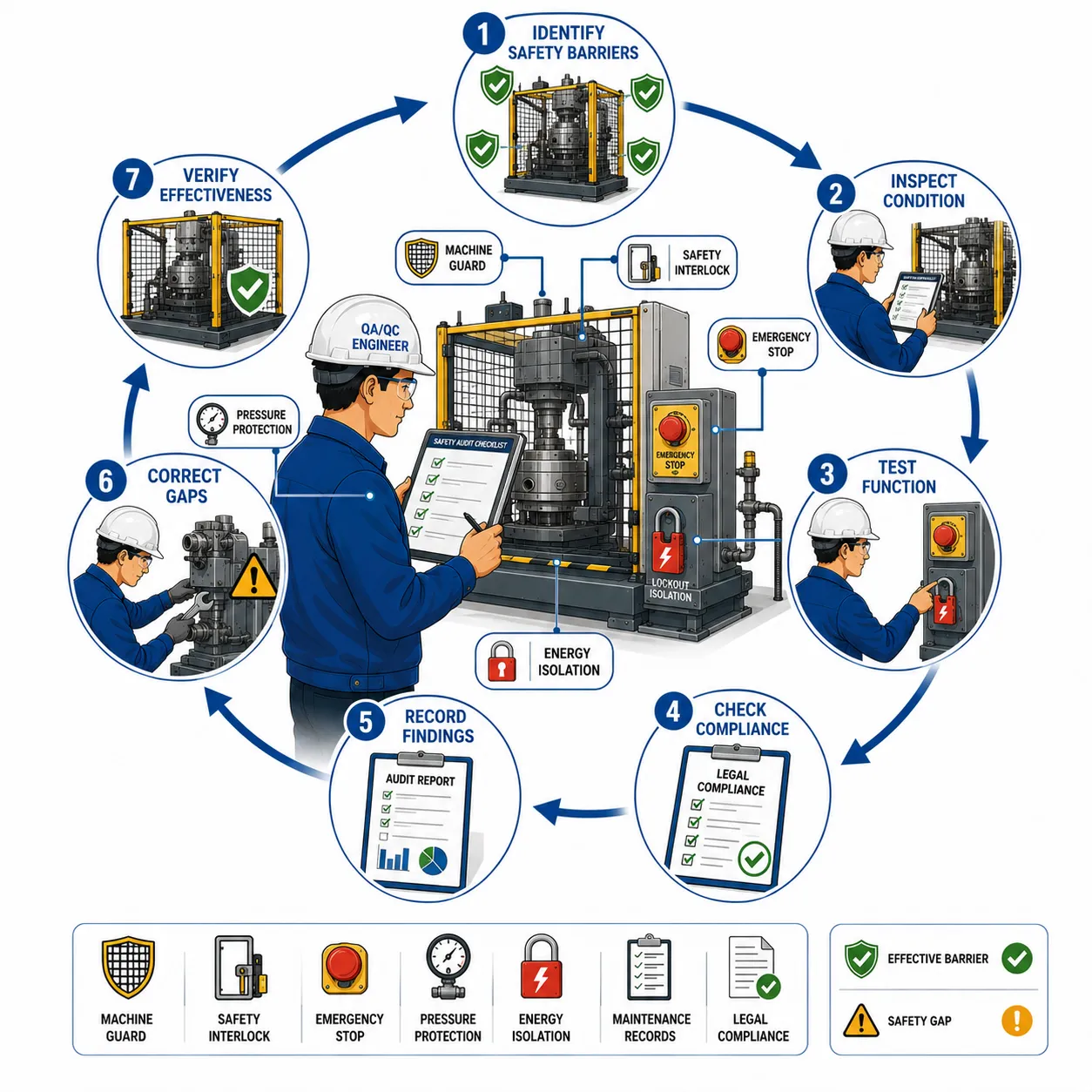
Understanding Risk Barriers and Safety Systems
A risk barrier is any control designed to prevent a hazardous event or reduce its consequences. Barriers may be physical, technical, procedural or organisational.
For example, a machine guard may prevent a worker from contacting moving parts, while an emergency stop system may allow equipment to be shut down quickly if an unsafe condition develops.
Safety systems are often made up of several connected controls. Their overall effectiveness depends on each component functioning correctly.
Common mechanical engineering risk barriers include:
Fixed and movable machine guards.
Safety interlocks.
Emergency stop systems.
Pressure relief devices.
Isolation valves.
Lockout and isolation arrangements.
Protective enclosures.
Safety alarms.
Fire detection systems.
Ventilation systems.
Load-limiting devices.
Overspeed protection systems.
Physical exclusion zones.
Warning signs and visual indicators.
Safe operating procedures.
Inspection and maintenance programmes.
An effective audit should recognise that safety is rarely dependent on one barrier alone. Many high-risk operations rely on multiple layers of protection.
Why Regular Auditing Is Necessary
Safety controls can become less effective over time. Mechanical wear, environmental conditions, unauthorised modifications, inadequate maintenance and changes in operational practices can all affect performance.
For example, a machine guard may originally have been correctly installed but later become loose, damaged or removed to make production activities easier. If this change is not detected, workers may be exposed to moving machinery without adequate protection.
Regular auditing helps organisations identify:
Deteriorating safety controls.
Missing or damaged barriers.
Outdated procedures.
Inadequate maintenance.
Unauthorised modifications.
Poor compliance with safe working requirements.
Changes in national legal obligations.
Gaps between documented procedures and actual practice.
The audit should focus on whether a barrier performs its intended function under realistic working conditions.
Key Definitions and Concepts
| Term | Definition | Application in Mechanical Engineering Safety |
|---|---|---|
| Risk barrier | A control intended to prevent a hazardous event or reduce its consequences | A physical guard preventing contact with rotating machinery |
| Safety system | A combination of technical and operational controls designed to manage safety risks | An interlocked enclosure with alarms and emergency shutdown |
| Barrier effectiveness | The extent to which a control performs its intended protective function | Testing whether an emergency stop safely stops hazardous movement |
| Compliance audit | A systematic examination of whether activities meet applicable requirements | Reviewing machine safety arrangements against legal and organisational requirements |
| Safety-critical control | A control whose failure could contribute directly to serious harm or major loss | Pressure relief protection on a pressurised system |
| Inspection | A planned examination to identify visible or measurable conditions | Checking the condition of a machine guard |
| Functional test | A test performed to confirm that a safety device operates as intended | Testing whether an interlock prevents machine start-up |
| Preventive maintenance | Planned maintenance intended to prevent deterioration or failure | Scheduled servicing of emergency shutdown equipment |
| Non-conformity | A failure to meet a specified requirement | A required safety inspection record is missing |
| Corrective action | Action taken to address the cause of an identified problem | Repairing and securing a damaged machine guard |
The Relationship Between Safety Auditing and National Engineering Safety Laws
National engineering safety laws establish legal duties that organisations must consider when managing mechanical hazards. The exact legal requirements differ between countries and jurisdictions. Therefore, a mechanical engineering organisation should identify the national laws, regulations, statutory requirements and competent authority guidance that apply to its location and activities.
An effective audit should not assume that one general international standard automatically replaces national legal obligations. International standards and industry guidance may support good practice, but legal compliance must be assessed against the requirements that are applicable within the relevant jurisdiction.
The organisation should maintain an up-to-date register of applicable requirements, which may include requirements relating to:
Machinery safety.
Workplace safety.
Pressure systems.
Lifting equipment.
Electrical safety.
Hazardous energy isolation.
Fire protection.
Inspection and maintenance.
Competent persons.
Incident reporting.
Record retention.
Establishing the Applicable Legal Requirements
Before conducting a compliance audit, the organisation should identify exactly which requirements apply to the equipment and activity being reviewed.
This may involve:
Reviewing national legislation.
Reviewing engineering regulations.
Checking regulatory authority guidance.
Reviewing statutory inspection requirements.
Consulting competent legal or technical specialists where necessary.
Identifying client-specific obligations.
The audit criteria should then be documented clearly.
Avoiding Unsupported Legal Assumptions
Auditors should avoid making assumptions about legal requirements.
For example, stating that a particular inspection interval is legally required without verifying the applicable jurisdiction could lead to incorrect compliance decisions.
Good practice is to:
Identify the applicable jurisdiction.
Confirm the relevant legal requirement.
Record the source of the requirement.
Apply the requirement to the specific equipment or activity.
Identifying Safety-Critical Risk Barriers
Not every workplace control has the same level of importance. Some barriers provide essential protection against serious hazards and require greater attention during audits.
Safety-critical barriers should be identified through the organisation’s risk assessment process.
Examples may include:
Emergency shutdown systems.
Pressure relief protection.
Machine guarding.
Safety interlocks.
Overspeed protection.
Load-limiting devices.
Emergency isolation systems.
Protective enclosures.
The failure of a safety-critical barrier may significantly increase risk.
Developing a Barrier Register
A barrier register can help the organisation manage important controls systematically.
The register may include:
Barrier identification number.
Equipment or process location.
Hazard being controlled.
Required function.
Inspection frequency.
Maintenance requirements.
Responsible person.
Applicable legal requirement.
A structured register improves traceability and makes audits more efficient.
Planning a Safety Barrier Audit
Effective audits require preparation. Auditing without a clear scope can result in inconsistent findings.
Define the Audit Objectives
The objectives should explain what the audit is intended to achieve.
Typical objectives include:
Confirming that safety barriers are installed.
Verifying that barriers remain effective.
Checking maintenance arrangements.
Reviewing legal compliance.
Identifying non-conformities.
Evaluating corrective actions.
Define the Audit Scope
The scope should identify:
Locations.
Equipment.
Processes.
Safety systems.
Documents.
The audit may focus on a specific mechanical workshop or cover the entire manufacturing facility.
Prepare an Audit Checklist
A checklist provides structure but should not replace professional judgement.
Typical checklist questions may include:
Is the barrier physically present?
Is it correctly installed?
Is it free from damage?
Has it been maintained?
Has it been functionally tested?
Are records available?
Are workers using the system correctly?
The Safety Barrier Audit Process
Step 1: Review Documentation
The audit should begin with relevant records.
Documents may include:
Risk assessments.
Safety procedures.
Equipment manuals.
Maintenance records.
Inspection reports.
Previous audit reports.
Training records.
Test certificates.
The objective is to understand the intended safety arrangements before observing the workplace.
Step 2: Conduct a Physical Inspection
The auditor should examine actual workplace conditions.
Physical inspection may identify:
Missing guards.
Damaged barriers.
Obstructed emergency equipment.
Unauthorised modifications.
Poor signage.
The physical condition should be compared against approved requirements.
Step 3: Verify Functional Performance
Visual inspection alone may not confirm effectiveness.
Where appropriate and safely authorised, functional testing may be required.
Examples include:
Testing emergency stop systems.
Checking safety interlocks.
Verifying alarm operation.
Testing shutdown sequences.
Functional tests should follow approved procedures and should not introduce unnecessary risk.
Step 4: Review Maintenance Evidence
A barrier may appear satisfactory while maintenance requirements have not been followed.
The auditor should review:
Planned maintenance schedules.
Completed maintenance records.
Outstanding defects.
Test certificates.
Step 5: Interview Relevant Personnel
Workers can provide valuable information about actual conditions.
Questions may address:
How the system operates.
Whether defects occur.
How problems are reported.
Whether procedures are practical.
Step 6: Record Audit Findings
Findings should be based on objective evidence.
Evidence may include:
Observations.
Records.
Photographs where authorised.
Test results.
Assessing Barrier Effectiveness
The key audit question is:
Does the barrier reliably perform its intended safety function?
Effectiveness should consider several factors.
Availability
The barrier must be present and available when needed.
A guard stored away from the machine does not provide effective protection.
Functionality
The barrier must operate correctly.
An emergency stop button that does not stop hazardous movement is ineffective.
Reliability
The barrier should operate consistently.
Repeated faults may indicate poor reliability.
Suitability
The barrier must be suitable for the hazard.
A weak temporary barrier may not adequately protect against a high-energy mechanical hazard.
Independence
Where multiple barriers are used, excessive dependence on a single failure point should be avoided where practicable.
Human Interaction
The barrier should support safe behaviour.
Poorly designed systems may encourage workers to bypass controls.
Auditing Machine Guards
Machine guarding is a common area of mechanical safety auditing.
The audit should examine:
Physical condition.
Secure installation.
Adequate coverage.
Resistance to removal.
Interlock operation where fitted.
Access to hazardous areas.
Common Machine Guard Failures
Examples include:
Guards removed for maintenance.
Damaged panels.
Loose fixings.
Excessive gaps.
Bypassed interlocks.
Each condition should be assessed against the applicable requirements.
Auditing Emergency Stop Systems
Emergency stop systems should be accessible and functional.
The audit should examine:
Location.
Identification.
Accessibility.
Functional performance.
Reset requirements.
The auditor should verify that testing and maintenance are documented.
Auditing Pressure Protection Systems
Pressurised mechanical systems may rely on protective devices to prevent excessive pressure.
Audit activities may include reviewing:
Inspection status.
Test records.
Maintenance history.
Evidence of damage.
Pressure-related systems may also be subject to specific national legal requirements.
Therefore, the applicable legal obligations should be verified.
Auditing Lockout and Energy Isolation Systems
Mechanical maintenance activities may involve hazardous energy.
The audit should consider:
Isolation points.
Identification.
Locking arrangements.
Verification procedures.
Training.
The organisation should confirm that actual practice matches approved procedures.
Auditing Safety Interlocks
Interlocks are designed to prevent unsafe operation.
Examples include systems that prevent equipment from starting when:
A guard is open.
A protective door is unlocked.
A safety condition has not been met.
The audit should consider whether interlocks:
Function correctly.
Have been bypassed.
Are properly maintained.
Are tested at appropriate intervals.
Using Risk-Based Audit Frequency
Not every safety barrier requires the same audit frequency.
Audit frequency should consider:
Hazard severity.
Probability of failure.
Equipment use.
Previous failures.
Legal requirements.
Safety-critical controls may require more frequent review.
A risk-based approach can help allocate resources effectively.
Practical Example: Auditing a Machine Guard
During an audit, a QA/QC and safety representative inspect a mechanical workshop.
The approved machine risk assessment identifies a fixed guard as a critical control.
The audit finds that:
The guard is installed.
The guard has a damaged fixing.
Workers report that vibration causes movement.
Although the guard is present, its effectiveness is reduced.
Corrective action includes:
Repairing the fixing.
Inspecting similar equipment.
Reviewing maintenance requirements.
The effectiveness of the repair should then be verified.
Practical Example: Auditing an Emergency Shutdown System
A factory has an emergency shutdown system for a high-risk mechanical process.
The audit identifies that functional testing is performed, but records are incomplete.
The auditor cannot verify whether all required tests have been completed.
The organisation should:
Investigate the documentation gap.
Confirm the actual condition of the system.
Complete any required verification.
Strengthen record controls.
This example demonstrates that documentation is part of compliance evidence.
Practical Example: Identifying a Bypassed Interlock
During a workshop inspection, an auditor observes that an interlocked access door remains operational even when opened.
Further investigation reveals that the interlock has been bypassed.
The condition represents a potentially serious loss of protection.
The appropriate response may include:
Making the equipment safe.
Escalating the issue.
Restoring the approved safety function.
Investigating the reason for the bypass.
The organisation should also review whether similar bypass practices exist elsewhere.
Recording Non-Conformities
Audit findings should be recorded clearly.
A professional non-conformity record should include:
Requirement.
Objective evidence.
Description of the gap.
Risk level.
Required action.
Responsible person.
Completion deadline.
Findings should be factual rather than based on personal opinion.
Classifying Findings
Organisations may classify findings according to internal procedures.
Categories may include:
Conformity.
Observation.
Minor non-conformity.
Major non-conformity.
The classification should reflect the significance of the issue.
Corrective Action and Follow-Up
Identifying a problem is only the beginning.
The organisation must ensure that corrective action is completed and effective.
A strong process includes:
Immediate containment where necessary.
Investigation of the cause.
Corrective action planning.
Implementation.
Effectiveness verification.
Closure.
Root Cause Analysis
Repeated barrier failures may indicate an underlying weakness.
Potential causes may include:
Poor maintenance.
Inadequate design.
Insufficient training.
Production pressure.
Weak supervision.
The corrective action should address the underlying cause.
Maintaining Compliance Documentation
Safety audits should generate traceable records.
Records may include:
Audit plans.
Checklists.
Inspection reports.
Test records.
Non-conformity reports.
Corrective action records.
Verification evidence.
Records should be controlled and readily retrievable.
Competence of Auditors
Personnel auditing safety barriers should have appropriate competence.
Competence may include:
Mechanical engineering knowledge.
Understanding of relevant hazards.
Audit skills.
Knowledge of applicable requirements.
Complex systems may require specialist technical input.
An auditor should recognise when expert support is necessary.
Common Weaknesses in Safety Barrier Audits
Treating Audits as Paper Exercises
A documentation review alone may not reveal whether a barrier works.
Physical verification is essential.
Checking Presence Rather Than Effectiveness
A guard can be present but damaged.
The audit must evaluate performance.
Failing to Review Changes
Equipment modifications can affect safety barriers.
Changes should be reviewed systematically.
Closing Actions Without Verification
An action should not be considered complete merely because someone states that it has been completed.
Effectiveness should be verified.
Key Benefits of Regular Safety System Audits
Improved Legal Compliance
Audits help identify gaps before regulatory inspections.
Reduced Accident Risk
Weak barriers can be identified and corrected.
Improved Asset Reliability
Safety systems and equipment receive structured attention.
Better Evidence for Management
Audit results provide objective information.
Continuous Improvement
Recurring findings can identify systemic weaknesses.
Developing a Continuous Improvement Cycle
Safety barrier auditing should operate as part of an ongoing cycle.
Plan
Identify:
Applicable requirements.
Critical barriers.
Audit frequency.
Do
Conduct inspections and tests.
Check
Evaluate:
Results.
Findings.
Trends.
Act
Implement improvements.
This cycle supports continuous development.
Integrating Safety Barrier Audits with QA/QC Systems
Safety and quality systems should not operate completely separately.
QA/QC personnel can contribute by:
Verifying inspection records.
Reviewing equipment conformity.
Supporting evidence-based decisions.
Monitoring corrective actions.
Integrated systems can reduce duplication.
Best Practice Principles
Effective audits of risk barriers and safety systems should:
Identify applicable national requirements.
Focus on barrier effectiveness.
Prioritise safety-critical controls.
Combine document review with workplace verification.
Conduct functional testing where appropriate.
Use objective evidence.
Record findings clearly.
Implement corrective actions.
Verify effectiveness.
Conclusion
Regular auditing of installed risk barriers and safety systems is essential for maintaining safe and compliant mechanical engineering operations. A safety barrier cannot be assumed to remain effective simply because it was correctly installed in the past. Mechanical wear, inadequate maintenance, unauthorised modifications and changes in operational practices can reduce the reliability of critical controls.
An effective audit evaluates the complete safety system. It considers whether barriers are available, functional, reliable and suitable for the hazards they are intended to control. Physical inspections, documentation reviews, functional tests and discussions with workers provide valuable evidence.
Particular attention should be given to safety-critical controls such as machine guards, emergency shutdown systems, pressure protection devices, safety interlocks and hazardous energy isolation arrangements. These controls may require risk-based inspection frequencies and clear maintenance responsibilities.
Legal compliance must also be assessed carefully. National engineering safety laws and regulations vary by jurisdiction, and organisations should maintain an accurate understanding of the requirements applicable to their activities and equipment.
By identifying weaknesses early, implementing effective corrective actions and verifying improvements, organisations can maintain stronger safety barriers, reduce the likelihood of serious incidents and support a reliable culture of risk management. Regular auditing therefore provides an essential connection between engineering design, operational practice, legal compliance and continuous improvement in mechanical QA/QC systems.