
Lesson No 1: Non-Destructive Testing (NDT) in Mechanical Engineering
Non-Destructive Testing (NDT) is a critical inspection technique used in mechanical engineering to evaluate the quality, integrity, and reliability of materials, components, and equipment without causing any damage or reducing their future serviceability. In modern Quality Assurance (QA) and Quality Control (QC) systems, NDT enables engineers and inspectors to identify surface and internal defects, verify manufacturing quality, and confirm that mechanical products comply with engineering specifications and safety requirements. Industries such as oil and gas, petrochemical, power generation, aerospace, automotive, marine, and heavy manufacturing widely use NDT methods to maintain product reliability and operational safety.
From the perspective of a QA/QC Mechanical Engineer, Non-Destructive Testing is an essential quality control approach that supports defect prevention, risk management, and continuous improvement throughout the engineering lifecycle. Techniques such as Visual Testing (VT), Ultrasonic Testing (UT), Radiographic Testing (RT), Magnetic Particle Testing (MT), and Dye Penetrant Testing (PT) allow professionals to detect cracks, corrosion, weld imperfections, material discontinuities, and structural weaknesses without damaging the inspected component. These methods provide valuable inspection data that helps organisations meet international engineering standards, customer requirements, and quality management systems such as ASME, ASTM, API, and ISO-based practices.
This lesson provides a comprehensive introduction to the principles, applications, and importance of Non-Destructive Testing (NDT) in Mechanical Engineering. Learners will explore how NDT supports mechanical inspection activities by improving defect detection, enhancing equipment reliability, reducing operational risks, and extending the service life of engineering assets. By developing an understanding of NDT processes and techniques, mechanical engineering professionals can make informed quality decisions, ensure compliance with technical specifications, and contribute to the safe delivery of reliable mechanical products and systems in global engineering environments.
1. Understand the Principles of Non-Destructive Testing (NDT) and Its Significance in Assessing Mechanical Materials Without Causing Damage
Non-Destructive Testing (NDT) is a fundamental inspection approach used in mechanical engineering to evaluate the condition, quality, and integrity of materials, components, and equipment without causing permanent damage or affecting their future operation. In modern Quality Assurance (QA) and Quality Control (QC) systems, NDT provides engineers with reliable methods to identify defects, evaluate material conditions, and verify manufacturing quality while preserving the usability of the inspected component.
For a QA/QC Mechanical Engineer, understanding the principles of NDT is essential because many mechanical components operate under demanding conditions involving pressure, temperature, vibration, fatigue loading, and corrosive environments. Failure of critical components such as pipelines, pressure vessels, rotating equipment, and structural parts can lead to safety risks, production losses, and costly repairs. NDT techniques allow professionals to detect potential failures before they occur, supporting preventive maintenance, risk management, and improved operational reliability.
Unlike destructive testing methods that require damaging or breaking a sample to determine material properties, NDT examines components while keeping them intact. Techniques such as Visual Testing (VT), Ultrasonic Testing (UT), Radiographic Testing (RT), Magnetic Particle Testing (MT), and Dye Penetrant Testing (PT) provide valuable information about surface and internal conditions. These methods are widely applied in industries including oil and gas, aerospace, power generation, automotive, marine, construction, and manufacturing to ensure compliance with engineering specifications and international standards.
Understanding Non-Destructive Testing (NDT)
Definition of Non-Destructive Testing
Non-Destructive Testing (NDT) is a group of inspection methods used to examine materials, components, and structures to detect defects, discontinuities, or changes in material properties without damaging the object being tested.
The main purpose of NDT is to determine whether a component is:
- Safe for operation.
- Manufactured according to specifications.
- Free from unacceptable defects.
- Suitable for continued service.
- Compliant with quality requirements.
NDT allows engineers to inspect the actual component rather than relying only on sample testing, making it highly valuable for safety-critical mechanical systems.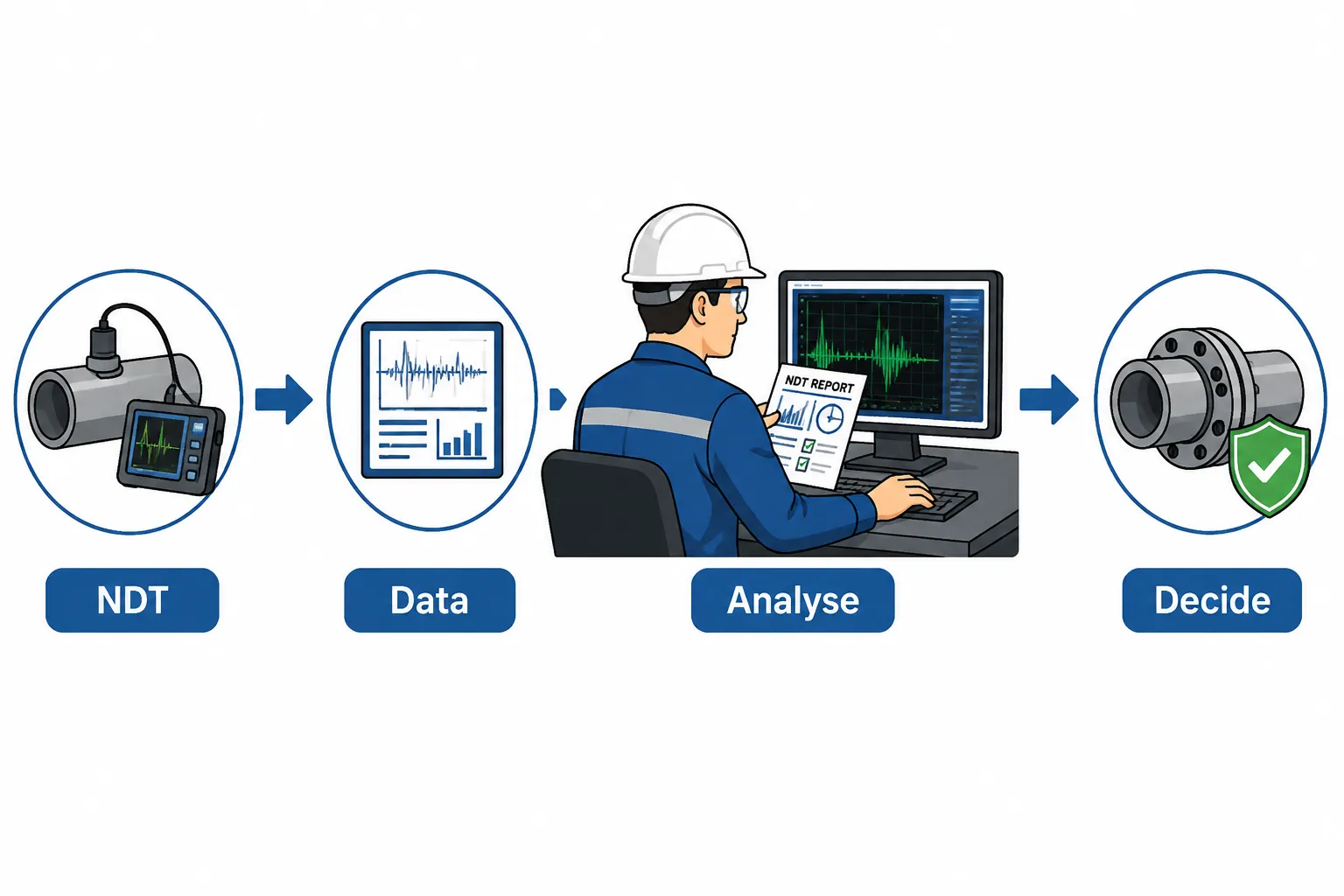
Key Characteristics of NDT
The major characteristics of NDT include:
- Inspection without component destruction.
- Ability to detect surface and internal defects.
- Preservation of component usability.
- Application during manufacturing and service life.
- Support for preventive maintenance.
- Compliance with engineering standards.
- Improvement of product reliability.
Fundamental Principles of Non-Destructive Testing
The effectiveness of NDT depends on applying scientific principles to identify differences between acceptable and defective material conditions.
Principle of Material Examination
Every material has specific physical and mechanical properties. Defects such as cracks, voids, inclusions, and discontinuities create changes in these properties.
NDT methods detect these changes by using:
- Sound waves.
- Magnetic fields.
- Radiation.
- Penetrating liquids.
- Visual examination.
- Electrical signals.
Principle of Defect Detection
A defect creates an abnormal response during inspection.
For example:
- A crack may interrupt ultrasonic waves.
- A weld defect may appear on a radiographic image.
- A surface crack may attract magnetic particles.
- A surface opening may absorb penetrant liquid.
Inspectors analyse these responses to determine whether the component meets acceptance criteria.
Principle of Non-Damage Assessment
The primary principle of NDT is that inspection should not affect the future performance of the component.
This means:
- No cutting is required.
- No material removal occurs.
- No structural damage is introduced.
- Components can continue operating after inspection.
Importance of NDT in Mechanical Engineering
NDT plays a vital role in maintaining the safety, reliability, and performance of mechanical products and systems.
Mechanical components are often exposed to:
- High operating pressures.
- Extreme temperatures.
- Repeated loading.
- Corrosive environments.
- Mechanical vibration.
- Continuous operation.
Under these conditions, small defects can develop into major failures if they are not detected early.
Why NDT is Important
NDT helps organisations to:
- Detect hidden defects.
- Prevent unexpected equipment failures.
- Improve product reliability.
- Reduce maintenance costs.
- Increase equipment lifespan.
- Maintain safety standards.
- Verify manufacturing quality.
- Support regulatory compliance.
- Reduce operational risks.
- Improve customer confidence.
Role of NDT in Quality Assurance and Quality Control
NDT is an essential part of mechanical QA/QC processes because it provides objective evidence about product quality and material condition.
A QA/QC Mechanical Engineer uses NDT to verify:
- Material integrity.
- Welding quality.
- Structural condition.
- Manufacturing accuracy.
- Equipment reliability.
- Compliance with specifications.
NDT Applications in Mechanical Engineering
NDT is commonly applied during:
- Raw material inspection.
- Welding inspection.
- Fabrication inspection.
- Equipment commissioning.
- Preventive maintenance.
- Repair verification.
- Final acceptance testing.
Examples of inspected components include:
- Pressure vessels.
- Pipelines.
- Storage tanks.
- Shafts.
- Gears.
- Welded structures.
- Valves.
- Heat exchangers.
- Rotating equipment.
Common Non-Destructive Testing Methods
Different NDT methods are selected depending on the material type, defect location, component design, and inspection requirements.
Visual Testing (VT)
Definition
Visual Testing is the simplest NDT method involving direct examination of a component using human observation or optical tools.
It is often the first inspection method performed before applying advanced techniques.
Applications
Visual inspection is used for:
- Surface crack detection.
- Weld examination.
- Corrosion identification.
- Surface damage assessment.
- Assembly verification.
Advantages
- Simple procedure.
- Low cost.
- Quick inspection.
- No special equipment required.
Ultrasonic Testing (UT)
Definition
Ultrasonic Testing uses high-frequency sound waves to detect internal defects within materials.
The sound waves travel through the component and reflect when they encounter discontinuities.
Applications
UT is used for:
- Weld inspection.
- Thickness measurement.
- Internal crack detection.
- Material evaluation.
Advantages
- Detects internal defects.
- Provides accurate location information.
- Suitable for thick materials.
- Does not damage components.
Radiographic Testing (RT)
Definition
Radiographic Testing uses X-rays or gamma rays to create images showing internal conditions of components.
Applications
RT is commonly used for:
- Weld examination.
- Pipeline inspection.
- Pressure vessel inspection.
Advantages
- Provides permanent inspection records.
- Detects internal defects.
- Useful for complex components.
Magnetic Particle Testing (MT)
Definition
Magnetic Particle Testing detects surface and near-surface defects in ferromagnetic materials by using magnetic fields and magnetic particles.
Applications
Used for inspecting:
- Steel shafts.
- Welds.
- Machinery components.
- Structural parts.
Dye Penetrant Testing (PT)
Definition
Dye Penetrant Testing uses a coloured liquid or fluorescent material to reveal surface-breaking defects.
Applications
Used for:
- Aluminium components.
- Stainless steel parts.
- Non-porous materials.
Comparison of Common NDT Methods
| NDT Method | Definition | Detects | Common Applications | Main Benefit |
|---|---|---|---|---|
| Visual Testing (VT) | Direct examination of surfaces using observation or optical tools | Surface defects, corrosion, damage | Welds, fabrication, maintenance | Simple and cost-effective |
| Ultrasonic Testing (UT) | Uses high-frequency sound waves to identify internal conditions | Internal cracks, flaws, thickness variations | Welds, pressure equipment, metals | Accurate internal inspection |
| Radiographic Testing (RT) | Uses radiation to create images of internal structures | Internal weld defects, voids, inclusions | Pipelines, vessels, assemblies | Permanent inspection records |
| Magnetic Particle Testing (MT) | Uses magnetic fields and particles to reveal defects | Surface and near-surface cracks | Steel components, shafts | Fast crack detection |
| Dye Penetrant Testing (PT) | Uses liquid penetrants to reveal surface openings | Surface cracks and discontinuities | Non-porous materials | Effective surface inspection |
NDT Inspection Process and Procedure
A professional NDT process follows a structured approach to ensure accurate and reliable results.
Step 1: Review Inspection Requirements
Before testing begins, inspectors review:
- Engineering drawings.
- Material specifications.
- Applicable standards.
- Inspection procedures.
- Acceptance criteria.
Step 2: Select Appropriate NDT Method
The selected method depends on:
- Material type.
- Defect location.
- Component thickness.
- Inspection purpose.
- Required accuracy.
Step 3: Prepare the Component
Preparation may include:
- Cleaning surfaces.
- Removing contaminants.
- Ensuring accessibility.
- Checking component identification.
Step 4: Perform NDT Examination
The inspector carries out the selected test according to approved procedures.
Activities include:
- Applying inspection equipment.
- Monitoring results.
- Recording indications.
- Evaluating findings.
Step 5: Analyse and Report Results
Inspection results are compared with acceptance criteria.
Reports include:
- Component details.
- Inspection method.
- Findings.
- Defect evaluation.
- Acceptance decision.
Role of QA/QC Mechanical Engineer in NDT
QA/QC Mechanical Engineers ensure that NDT activities are properly planned, performed, and documented.
Their responsibilities include:
- Selecting suitable NDT methods.
- Reviewing inspection procedures.
- Confirming inspector qualifications.
- Checking equipment calibration.
- Reviewing NDT reports.
- Evaluating defect acceptance.
- Managing non-conformities.
- Maintaining quality records.
Practical Workplace Example
A QA/QC Mechanical Engineer is responsible for inspecting a welded pipeline system before commissioning.
The engineer applies:
- Visual Testing to check weld appearance.
- Ultrasonic Testing to detect internal weld defects.
- Radiographic Testing for critical weld sections.
During ultrasonic testing, an internal indication is detected near a weld area. The result is reviewed against acceptance criteria, and the weld is identified as requiring repair.
The defective section is repaired and inspected again. After successful re-testing, the pipeline is approved for operation.
This example demonstrates how NDT prevents failures while allowing components to remain usable.
Case Study: NDT Inspection of Pressure Vessel Welds
Background
A manufacturing company produced pressure vessels for a chemical processing facility. Due to high-pressure operating conditions, strict inspection requirements were implemented.
NDT Activities
The QA/QC team performed:
- Visual Testing.
- Radiographic Testing.
- Ultrasonic Testing.
Issue Identified
Radiographic testing revealed internal weld porosity that could reduce vessel strength.
Corrective Action
The company:
- Removed the defective weld section.
- Performed repair welding.
- Conducted repeat NDT inspection.
- Updated welding controls.
Outcome
After correction:
- Weld quality met acceptance requirements.
- Pressure vessel integrity was confirmed.
- Customer approval was achieved.
- Operational safety was improved.
Key Benefits of Non-Destructive Testing
NDT provides significant advantages, including:
- Detecting defects without damaging components.
- Improving mechanical safety.
- Reducing equipment failures.
- Increasing product reliability.
- Supporting preventive maintenance.
- Extending equipment service life.
- Reducing repair costs.
- Improving quality assurance processes.
- Supporting international compliance.
- Increasing customer confidence.
Key Takeaways
- NDT evaluates mechanical materials without causing damage.
- NDT methods detect surface and internal defects.
- Different materials and defects require different inspection techniques.
- NDT supports QA/QC activities throughout the engineering lifecycle.
- Proper NDT procedures improve safety, reliability, and compliance.
- QA/QC Mechanical Engineers use NDT results to make informed quality decisions.
Conclusion
Non-Destructive Testing is a vital inspection technology that enables mechanical engineers to assess material integrity, detect defects, and verify component reliability without damaging valuable assets. By applying NDT principles and techniques, QA/QC professionals can ensure that mechanical products and systems meet required quality standards, safety expectations, and operational requirements.
The effective use of NDT supports preventive quality management by identifying potential failures before they occur, reducing risks, improving maintenance strategies, and extending equipment service life. Through proper selection of inspection methods, accurate result evaluation, and professional reporting, NDT remains an essential practice for achieving safe, reliable, and high-quality mechanical engineering outcomes.
2. Identify the Main Non-Destructive Testing (NDT) Methods Used in Mechanical Engineering
Non-Destructive Testing (NDT) methods are essential inspection techniques used in mechanical engineering to examine materials, components, and structures without causing permanent damage or affecting their future performance. In modern Quality Assurance (QA) and Quality Control (QC) systems, NDT provides reliable methods for detecting surface and internal defects, evaluating material integrity, and confirming that mechanical products meet engineering specifications and international quality standards.
From the perspective of a QA/QC Mechanical Engineer, selecting the correct NDT method is a critical decision because different inspection techniques are suitable for different materials, component designs, defect types, and operating conditions. For example, ultrasonic testing is highly effective for detecting internal defects, while dye penetrant testing is suitable for identifying surface-breaking cracks. Understanding the principles, applications, advantages, and limitations of each NDT method allows engineers to make accurate inspection decisions and maintain product reliability.
The main NDT methods used in mechanical engineering include Ultrasonic Testing (UT), Radiographic Testing (RT), Magnetic Particle Testing (MPT), Dye Penetrant Testing (DPT), and Eddy Current Testing (ECT). These techniques are widely applied in industries such as oil and gas, aerospace, power generation, automotive, marine, manufacturing, and construction to inspect welds, pressure equipment, pipelines, rotating machinery, and critical mechanical components.
Understanding Main NDT Methods in Mechanical Engineering
Definition of NDT Methods
NDT methods are scientific inspection techniques that use physical principles to identify defects, discontinuities, or changes in material properties without destroying or damaging the tested component.
The main objectives of NDT methods are to:
- Detect hidden defects.
- Confirm material integrity.
- Verify manufacturing quality.
- Prevent unexpected failures.
- Improve equipment reliability.
- Support maintenance decisions.
- Ensure compliance with engineering standards.
Importance of Selecting the Correct NDT Method
Choosing the appropriate NDT method depends on several factors:
- Material type.
- Component thickness.
- Defect location.
- Defect size.
- Inspection requirements.
- Accessibility of the inspection area.
- Required accuracy.
- Industry standards.
A QA/QC Mechanical Engineer must evaluate these factors before selecting an inspection technique.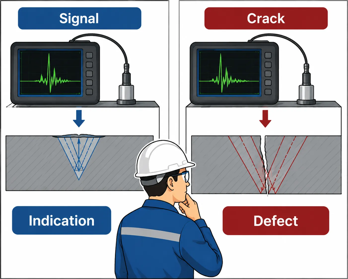
Ultrasonic Testing (UT)
Definition of Ultrasonic Testing
Ultrasonic Testing (UT) is a non-destructive inspection method that uses high-frequency sound waves to detect internal defects and measure material thickness. The technique works by transmitting ultrasonic waves into a component and analysing the reflected signals produced when the waves encounter discontinuities.
UT is one of the most widely used NDT methods because it provides accurate information about the location, size, and depth of internal defects.
Principle of Ultrasonic Testing
The basic principle of UT involves:
- Generation of ultrasonic waves using a transducer.
- Transmission of sound waves through the material.
- Reflection of waves from defects or boundaries.
- Analysis of received signals.
- Evaluation of defect characteristics.
When ultrasonic waves encounter a crack, void, or inclusion, part of the energy is reflected back to the equipment. The inspector analyses this response to determine the condition of the material.
Applications of Ultrasonic Testing
UT is commonly used for:
- Weld inspection.
- Thickness measurement.
- Pipeline examination.
- Pressure vessel inspection.
- Forging inspection.
- Corrosion monitoring.
- Structural component assessment.
Advantages of Ultrasonic Testing
UT provides several benefits:
- Detects internal defects.
- Provides accurate defect location.
- Measures material thickness.
- Does not damage components.
- Suitable for thick materials.
- Provides immediate results.
Limitations of Ultrasonic Testing
Some limitations include:
- Requires skilled operators.
- Surface preparation may be necessary.
- Complex shapes can be difficult to inspect.
- Interpretation requires technical knowledge.
Radiographic Testing (RT)
Definition of Radiographic Testing
Radiographic Testing (RT) is an NDT method that uses X-rays or gamma radiation to produce images of the internal structure of components. These images allow inspectors to identify internal defects that cannot be detected through visual examination.
RT is widely used for inspecting welds and safety-critical components where internal quality is essential.
Principle of Radiographic Testing
The RT process involves:
- Passing radiation through the component.
- Capturing transmitted radiation on film or digital detectors.
- Producing an image of internal conditions.
- Analysing the image for defects.
Areas with defects absorb radiation differently, creating visible differences on the radiographic image.
Applications of Radiographic Testing
RT is commonly applied to:
- Pressure vessels.
- Pipelines.
- Welded joints.
- Aerospace components.
- Casting inspection.
- Fabricated structures.
Defects Detected by RT
Radiographic testing can identify:
- Porosity.
- Internal cracks.
- Welding defects.
- Inclusions.
- Voids.
- Lack of fusion.
Advantages of Radiographic Testing
Benefits include:
- Provides permanent inspection records.
- Detects internal defects.
- Suitable for complex components.
- Provides detailed images.
Limitations of Radiographic Testing
Limitations include:
- Radiation safety requirements.
- Higher operational costs.
- Requires controlled inspection areas.
- Skilled interpretation is necessary.
Magnetic Particle Testing (MPT)
Definition of Magnetic Particle Testing
Magnetic Particle Testing (MPT), also known as Magnetic Particle Inspection (MPI), is an NDT technique used to detect surface and near-surface defects in ferromagnetic materials.
The method uses magnetic fields and magnetic particles to identify discontinuities such as cracks and material separation.
Principle of Magnetic Particle Testing
The process involves:
- Magnetising the component.
- Applying magnetic particles.
- Observing particle accumulation.
- Identifying defect locations.
When a crack interrupts the magnetic field, magnetic particles gather around the defect area, making it visible to the inspector.
Applications of Magnetic Particle Testing
MPT is used for inspecting:
- Steel shafts.
- Welded components.
- Gears.
- Bearings.
- Railway components.
- Heavy machinery parts.
Advantages of Magnetic Particle Testing
Benefits include:
- Quick inspection process.
- High sensitivity for cracks.
- Suitable for irregular surfaces.
- Effective for detecting small defects.
Limitations of Magnetic Particle Testing
Limitations include:
- Only works on magnetic materials.
- Surface cleaning is required.
- Does not detect deep internal defects.
- Requires proper magnetisation.
Dye Penetrant Testing (DPT)
Definition of Dye Penetrant Testing
Dye Penetrant Testing (DPT), also known as Liquid Penetrant Testing, is an NDT method used to detect surface-breaking defects in non-porous materials.
The technique uses a coloured or fluorescent liquid that enters surface openings and reveals hidden cracks after removal of excess penetrant.
Principle of Dye Penetrant Testing
The process involves:
- Cleaning the component surface.
- Applying penetrant liquid.
- Allowing penetration time.
- Removing excess liquid.
- Applying developer.
- Observing defect indications.
Applications of Dye Penetrant Testing
DPT is used for:
- Aluminium components.
- Stainless steel parts.
- Weld inspection.
- Turbine components.
- Machined surfaces.
Defects Detected by DPT
It identifies:
- Surface cracks.
- Porosity.
- Leakage paths.
- Surface discontinuities.
Advantages of Dye Penetrant Testing
Benefits include:
- Simple application.
- Low equipment cost.
- Suitable for complex shapes.
- Effective for small surface defects.
Limitations of Dye Penetrant Testing
Limitations include:
- Only detects surface defects.
- Requires clean surfaces.
- Not suitable for porous materials.
- Requires careful procedure control.
Eddy Current Testing (ECT)
Definition of Eddy Current Testing
Eddy Current Testing (ECT) is an electromagnetic NDT method used to detect surface and near-surface defects in electrically conductive materials.
The technique works by generating electrical currents within the material and analysing changes caused by defects or material variations.
Principle of Eddy Current Testing
ECT involves:
- Creating an alternating magnetic field.
- Inducing electrical currents in the material.
- Monitoring changes in electromagnetic response.
- Identifying defects.
Applications of Eddy Current Testing
ECT is commonly used for:
- Aircraft components.
- Heat exchanger tubes.
- Conductive metals.
- Weld inspection.
- Corrosion detection.
Advantages of Eddy Current Testing
Benefits include:
- Fast inspection speed.
- No direct contact required.
- Detects small surface defects.
- Suitable for automated inspection.
Limitations of Eddy Current Testing
Limitations include:
- Only works with conductive materials.
- Limited penetration depth.
- Requires skilled interpretation.
Comparison of Main NDT Methods
| NDT Method | Definition | Main Principle | Detects | Common Applications |
|---|---|---|---|---|
| Ultrasonic Testing (UT) | Uses high-frequency sound waves to inspect materials | Reflection of ultrasonic waves | Internal cracks, thickness variations | Welds, pipelines, pressure vessels |
| Radiographic Testing (RT) | Uses X-rays or gamma rays to create internal images | Radiation absorption differences | Internal weld defects, voids, inclusions | Pressure equipment, welded structures |
| Magnetic Particle Testing (MPT) | Uses magnetic fields and particles to identify defects | Magnetic leakage detection | Surface and near-surface cracks | Steel shafts, welds, machinery |
| Dye Penetrant Testing (DPT) | Uses liquid penetrants to reveal surface defects | Capillary action | Surface cracks and discontinuities | Aluminium, stainless steel components |
| Eddy Current Testing (ECT) | Uses electromagnetic fields to inspect conductive materials | Electrical current variation | Surface defects, corrosion | Heat exchangers, aircraft parts |
NDT Inspection Process and Procedure
A professional NDT inspection follows a controlled procedure to ensure accurate results.
Step 1: Review Inspection Requirements
The inspector reviews:
- Engineering specifications.
- Drawings.
- Applicable standards.
- Acceptance criteria.
- Inspection procedures.
Step 2: Select Suitable NDT Method
The method is selected based on:
- Material characteristics.
- Defect type.
- Component design.
- Inspection purpose.
Step 3: Prepare Component
Preparation includes:
- Cleaning surfaces.
- Removing contamination.
- Ensuring accessibility.
- Identifying inspection areas.
Step 4: Perform Examination
The inspector:
- Applies the selected NDT technique.
- Collects inspection data.
- Records indications.
- Evaluates results.
Step 5: Report and Evaluate Results
Inspection reports include:
- Component details.
- Test method.
- Findings.
- Defect evaluation.
- Acceptance decision.
Role of QA/QC Mechanical Engineer in NDT Application
A QA/QC Mechanical Engineer ensures that NDT activities are properly controlled and provide reliable quality evidence.
Responsibilities include:
- Selecting appropriate NDT techniques.
- Reviewing inspection procedures.
- Ensuring qualified personnel perform testing.
- Checking equipment calibration.
- Reviewing inspection reports.
- Evaluating defect acceptance.
- Managing non-conformities.
- Maintaining quality documentation.
Practical Workplace Example
A fabrication company manufactures pressure vessels for a chemical plant. Before final approval, the QA/QC Mechanical Engineer selects different NDT methods based on inspection requirements.
- Visual Testing checks weld appearance.
- Ultrasonic Testing identifies internal weld defects.
- Radiographic Testing confirms critical weld quality.
- Dye Penetrant Testing checks surface cracks.
- Magnetic Particle Testing examines steel components.
The combined use of NDT methods provides complete confidence that the pressure vessel meets safety and quality requirements.
Case Study: NDT Inspection of Pipeline Welding
Background
An oil and gas company installed a high-pressure pipeline system requiring strict quality verification.
NDT Activities
The QA/QC team performed:
- Radiographic Testing on weld joints.
- Ultrasonic Testing for internal inspection.
- Magnetic Particle Testing on critical areas.
Issue Identified
Radiographic inspection detected internal weld porosity that could weaken the pipeline.
Corrective Action
The defective weld was repaired and re-tested using approved NDT procedures.
Outcome
After successful inspection:
- Pipeline integrity was confirmed.
- Safety requirements were achieved.
- Client approval was obtained.
- Operational risks were reduced.
Key Benefits of Understanding NDT Methods
Knowledge of NDT methods provides several advantages:
- Improves defect detection capability.
- Supports effective quality control.
- Reduces equipment failure risks.
- Improves product reliability.
- Ensures compliance with standards.
- Supports preventive maintenance.
- Reduces repair costs.
- Enhances safety performance.
- Improves inspection decision-making.
- Increases customer confidence.
Key Takeaways
- NDT methods inspect materials without causing damage.
- Different NDT techniques detect different defect types.
- UT identifies internal defects using sound waves.
- RT provides images of internal conditions.
- MPT detects defects in magnetic materials.
- DPT identifies surface-breaking defects.
- ECT evaluates conductive materials using electromagnetic principles.
- Proper NDT selection is essential for accurate quality assessment.
Conclusion
Understanding the main Non-Destructive Testing methods is essential for mechanical engineering professionals involved in quality assurance and inspection activities. Techniques such as Ultrasonic Testing, Radiographic Testing, Magnetic Particle Testing, Dye Penetrant Testing, and Eddy Current Testing provide powerful solutions for evaluating material integrity without damaging valuable components.
For QA/QC Mechanical Engineers, selecting and applying the correct NDT method ensures that mechanical products meet engineering specifications, safety requirements, and international standards. By using appropriate inspection techniques, organisations can detect defects early, improve reliability, reduce operational risks, and maintain high-quality engineering performance throughout the product lifecycle.
3. Describe the Equipment and Procedures for Performing Each NDT Method in Mechanical Engineering
Non-Destructive Testing (NDT) equipment and procedures are essential elements of mechanical engineering inspection systems because they allow professionals to evaluate material integrity, detect defects, and verify component quality without causing damage. In Quality Assurance (QA) and Quality Control (QC) environments, the correct selection, operation, and application of NDT equipment directly influence the accuracy and reliability of inspection results.
From the perspective of a QA/QC Mechanical Engineer, performing NDT requires more than simply using inspection instruments. It involves understanding inspection principles, selecting appropriate equipment, following approved procedures, ensuring calibration accuracy, interpreting results correctly, and maintaining complete documentation. Each NDT method has specific equipment requirements and inspection procedures based on the material type, component design, defect characteristics, and applicable engineering standards.
Mechanical industries such as oil and gas, aerospace, power generation, manufacturing, construction, and heavy engineering rely on NDT equipment to inspect critical components including pipelines, pressure vessels, welds, shafts, gears, valves, and structural assemblies. Properly performed NDT examinations help identify defects at an early stage, prevent equipment failures, improve operational safety, and ensure compliance with international standards such as ASME, ASTM, API, and ISO quality requirements.
Understanding NDT Equipment and Inspection Procedures
Definition of NDT Equipment
NDT equipment refers to specialised tools, instruments, devices, and systems used to perform non-destructive examinations on materials and components.
The main purpose of NDT equipment is to:
- Generate inspection signals.
- Detect material changes.
- Identify defects.
- Measure component conditions.
- Record inspection results.
- Support quality decisions.
Examples of NDT equipment include:
- Ultrasonic flaw detectors.
- X-ray and gamma-ray systems.
- Magnetic yokes.
- Penetrant inspection materials.
- Eddy current probes.
- Digital recording systems.
Definition of NDT Procedures
NDT procedures are approved step-by-step instructions that define how an inspection method must be performed to achieve accurate and repeatable results.
A typical NDT procedure includes:
- Inspection requirements.
- Equipment details.
- Surface preparation requirements.
- Testing sequence.
- Calibration requirements.
- Acceptance criteria.
- Safety controls.
- Reporting methods.
Following approved procedures ensures that inspection results are reliable and meet engineering requirements.
Importance of Correct NDT Equipment Selection
Selecting suitable equipment is a critical responsibility of QA/QC professionals because incorrect equipment selection can result in inaccurate inspection findings.
The selection process considers:
- Material type.
- Component size.
- Defect location.
- Inspection environment.
- Required accuracy.
- Industry standards.
- Accessibility.
Correct equipment selection helps to:
- Improve defect detection.
- Reduce inspection errors.
- Increase reliability.
- Support compliance.
- Improve safety.
Ultrasonic Testing (UT) Equipment and Procedure
Definition of Ultrasonic Testing Equipment
Ultrasonic Testing (UT) equipment uses high-frequency sound waves to detect internal defects and measure material thickness.
The equipment sends ultrasonic waves into the component and analyses reflected signals from internal boundaries or defects.
Main UT Equipment
Common ultrasonic testing equipment includes:
Ultrasonic Flaw Detector
The main instrument used to generate and analyse ultrasonic signals.
Functions include:
- Producing electrical pulses.
- Receiving reflected signals.
- Displaying defect indications.
- Measuring defect location.
Transducers
Transducers convert electrical energy into ultrasonic waves and receive reflected signals.
Types include:
- Straight beam probes.
- Angle beam probes.
- Dual element probes.
Couplant Materials
Couplants improve sound transmission between the probe and component surface.
Examples include:
- Gel.
- Oil.
- Water-based solutions.
Calibration Blocks
Used to verify equipment accuracy before inspection.
UT Inspection Procedure
The typical UT procedure includes:
Step 1: Component Preparation
The inspector:
- Cleans the inspection surface.
- Removes contaminants.
- Identifies inspection areas.
Step 2: Equipment Calibration
Calibration is performed using reference blocks to confirm:
- Correct sensitivity.
- Accurate measurements.
- Reliable signal response.
Step 3: Performing Inspection
The inspector:
- Applies couplant.
- Moves the transducer across the surface.
- Monitors signals.
- Records indications.
Step 4: Result Evaluation
Results are compared against acceptance criteria.
Possible outcomes:
- Accepted condition.
- Defect requiring repair.
- Further evaluation required.
Radiographic Testing (RT) Equipment and Procedure
Definition of Radiographic Testing Equipment
Radiographic Testing equipment uses X-rays or gamma radiation to create images showing internal conditions of components.
RT is commonly used for inspecting weld quality in safety-critical applications.
Main RT Equipment
Radiation Source
Sources include:
- X-ray generators.
- Gamma-ray radioactive sources.
Radiographic Film or Digital Detector
Used to capture radiation images.
Exposure Equipment
Controls:
- Radiation positioning.
- Exposure time.
- Inspection distance.
Image Processing Equipment
Used for:
- Developing films.
- Digital image analysis.
- Recording inspection evidence.
RT Inspection Procedure
Step 1: Preparation
The inspection area is prepared by:
- Cleaning the surface.
- Positioning the component.
- Establishing safety controls.
Step 2: Equipment Setup
The inspector:
- Positions the radiation source.
- Places the detector.
- Calculates exposure requirements.
Step 3: Radiation Exposure
Radiation passes through the component and creates an internal image.
Step 4: Image Evaluation
The inspector analyses images for:
- Cracks.
- Porosity.
- Inclusions.
- Lack of fusion.
Magnetic Particle Testing (MPT) Equipment and Procedure
Definition of Magnetic Particle Testing Equipment
Magnetic Particle Testing equipment detects surface and near-surface defects in ferromagnetic materials using magnetic fields and magnetic particles.
Main MPT Equipment
Magnetic Yoke
Creates a magnetic field within the inspection area.
Magnetic Particles
Particles accumulate at defect locations.
Types include:
- Dry particles.
- Wet fluorescent particles.
UV Light Equipment
Used during fluorescent particle inspection.
Cleaning Equipment
Ensures accurate inspection results.
MPT Inspection Procedure
Step 1: Surface Preparation
The component surface is cleaned to remove:
- Oil.
- Dirt.
- Paint.
- Contamination.
Step 2: Magnetisation
A magnetic field is applied to the component.
Step 3: Particle Application
Magnetic particles are applied to the inspection area.
Step 4: Examination
The inspector observes particle patterns to identify defects.
Dye Penetrant Testing (DPT) Equipment and Procedure
Definition of Dye Penetrant Testing Equipment
Dye Penetrant Testing equipment uses liquid penetrants to identify surface-breaking defects in non-porous materials.
Main DPT Equipment
Cleaning Materials
Used for removing surface contamination.
Penetrant Liquid
A coloured or fluorescent liquid that enters surface defects.
Developer
Draws penetrant from defects to create visible indications.
Inspection Lighting
Includes:
- White light.
- Ultraviolet light for fluorescent testing.
DPT Inspection Procedure
Step 1: Surface Cleaning
The surface is cleaned to ensure proper penetrant action.
Step 2: Apply Penetrant
The penetrant is applied and allowed sufficient dwell time.
Step 3: Remove Excess Penetrant
Excess liquid is carefully removed.
Step 4: Apply Developer
Developer reveals defect locations.
Step 5: Evaluate Results
The inspector identifies:
- Cracks.
- Surface openings.
- Discontinuities.
Eddy Current Testing (ECT) Equipment and Procedure
Definition of Eddy Current Testing Equipment
Eddy Current Testing equipment uses electromagnetic principles to inspect electrically conductive materials.
Main ECT Equipment
Eddy Current Instrument
Generates electromagnetic signals.
Inspection Probes
Used to scan material surfaces.
Types include:
- Surface probes.
- Encircling coils.
- Internal probes.
Reference Standards
Used for calibration and comparison.
ECT Inspection Procedure
Step 1: Equipment Calibration
The system is calibrated using known reference defects.
Step 2: Probe Application
The probe is moved across the inspection area.
Step 3: Signal Analysis
Changes in electromagnetic response indicate possible defects.
Step 4: Result Documentation
Findings are recorded and evaluated.
Comparison of NDT Equipment and Procedures
| NDT Method | Main Equipment | Inspection Procedure | Common Applications |
|---|---|---|---|
| Ultrasonic Testing (UT) | Flaw detector, transducers, couplants, calibration blocks | Sound waves are transmitted and reflected signals are analysed | Welds, pipelines, pressure vessels |
| Radiographic Testing (RT) | X-ray machines, gamma sources, detectors | Radiation creates images showing internal conditions | Weld inspection, pressure equipment |
| Magnetic Particle Testing (MPT) | Magnetic yokes, particles, UV lights | Components are magnetised and particle indications are examined | Steel components and welds |
| Dye Penetrant Testing (DPT) | Penetrant, cleaner, developer, lighting | Liquid penetrant reveals surface defects | Non-porous materials |
| Eddy Current Testing (ECT) | Instruments, probes, reference standards | Electromagnetic changes identify defects | Conductive metals and tubes |
Role of QA/QC Mechanical Engineer in NDT Procedures
QA/QC Mechanical Engineers ensure that NDT activities are performed correctly and according to approved standards.
Their responsibilities include:
- Reviewing NDT procedures.
- Selecting appropriate inspection methods.
- Confirming equipment calibration.
- Checking inspector qualifications.
- Monitoring inspection activities.
- Reviewing test reports.
- Evaluating defects.
- Ensuring documentation accuracy.
- Managing non-conformities.
- Supporting quality audits.
Practical Workplace Example
A manufacturing company produces pressure vessels for an industrial plant. Before delivery, the QA/QC Mechanical Engineer develops an NDT inspection plan.
The inspection process includes:
- Visual Testing for surface conditions.
- Ultrasonic Testing for internal weld examination.
- Radiographic Testing for critical joints.
- Dye Penetrant Testing for surface cracks.
During ultrasonic testing, an internal weld indication is detected. The engineer reviews the result, compares it with acceptance criteria, and identifies the weld as requiring repair.
After repair and repeat inspection, the pressure vessel successfully meets quality requirements.
Case Study: NDT Equipment Application in Pipeline Inspection
Background
An oil and gas company required inspection of a newly fabricated pipeline system before operation.
NDT Activities
The QA/QC team used:
- Ultrasonic Testing equipment for weld inspection.
- Radiographic equipment for critical joints.
- Magnetic Particle Testing for steel connections.
Problem Identified
Radiographic testing detected internal weld defects.
Corrective Action
The company:
- Repaired defective welds.
- Repeated NDT inspections.
- Updated welding controls.
Outcome
The pipeline achieved:
- Compliance with engineering requirements.
- Improved reliability.
- Safe operational approval.
Key Benefits of Proper NDT Equipment and Procedures
Effective use of NDT equipment provides:
- Accurate defect detection.
- Improved inspection reliability.
- Reduced equipment failure.
- Enhanced safety.
- Better quality control.
- Longer equipment lifespan.
- Reduced maintenance costs.
- Compliance with standards.
- Improved customer confidence.
- Better engineering decision-making.
Key Takeaways
- Each NDT method requires specific equipment and procedures.
- Calibration is essential for accurate inspection results.
- UT detects internal defects using sound waves.
- RT identifies internal conditions through radiation images.
- MPT detects defects in magnetic materials.
- DPT identifies surface-breaking defects.
- ECT evaluates conductive materials using electromagnetic principles.
- QA/QC engineers ensure NDT activities meet technical and quality requirements.
Conclusion
Understanding NDT equipment and procedures is essential for mechanical engineering professionals involved in quality inspection and assurance. Each NDT method requires specialised equipment, controlled procedures, and skilled interpretation to produce accurate results.
For QA/QC Mechanical Engineers, proper application of NDT techniques ensures that mechanical components meet engineering specifications, safety requirements, and international standards. By selecting suitable equipment, following approved procedures, and maintaining accurate inspection records, organisations can prevent failures, improve reliability, and achieve high levels of mechanical product quality.
4. Assess the Advantages and Limitations of Different NDT Methods Based on Material Type, Geometry, and Application
Non-Destructive Testing (NDT) is a critical quality assurance and inspection approach used in mechanical engineering to evaluate the condition, integrity, and reliability of materials and components without causing permanent damage. However, selecting the most suitable NDT method requires professional judgement because every inspection technique has specific advantages, limitations, and application requirements. A method that provides excellent results for one material or component may not be suitable for another due to differences in material properties, component geometry, defect location, accessibility, and operational conditions.
From the perspective of a QA/QC Mechanical Engineer, choosing the correct NDT method is an important quality decision that directly affects inspection accuracy, safety, and compliance. Engineers must evaluate factors such as whether the material is metallic or non-metallic, magnetic or non-magnetic, thin or thick, simple or complex in shape, and whether defects are expected on the surface or internally. The selected inspection method must provide reliable information while meeting project specifications, customer requirements, and international standards such as ASME, ASTM, API, and ISO requirements.
The main NDT methods used in mechanical engineering include Ultrasonic Testing (UT), Radiographic Testing (RT), Magnetic Particle Testing (MPT), Dye Penetrant Testing (DPT), and Eddy Current Testing (ECT). Each method has unique capabilities. Understanding their strengths and limitations allows QA/QC professionals to develop effective inspection strategies, reduce operational risks, improve equipment reliability, and ensure mechanical components are safe for service.
Understanding NDT Method Selection in Mechanical Engineering
Definition of NDT Method Selection
NDT method selection is the process of choosing the most appropriate inspection technique based on the characteristics of the material, component design, expected defects, inspection requirements, and operational application.
A suitable NDT method should:
- Detect the required defect type.
- Provide accurate inspection results.
- Be suitable for the material.
- Access the required inspection area.
- Meet applicable standards.
- Provide cost-effective results.
Factors Affecting NDT Method Selection
A QA/QC Mechanical Engineer considers several factors before selecting an NDT method:
- Material composition.
- Magnetic properties.
- Electrical conductivity.
- Component thickness.
- Component geometry.
- Surface condition.
- Defect location.
- Inspection accessibility.
- Safety requirements.
- Industry standards.
Relationship Between Material Type and NDT Selection
Material properties significantly influence the effectiveness of NDT methods.
Ferromagnetic Materials
Ferromagnetic materials such as steel and iron are suitable for:
- Magnetic Particle Testing (MPT).
- Ultrasonic Testing (UT).
- Radiographic Testing (RT).
MPT is particularly effective because magnetic fields can reveal cracks and discontinuities.
Non-Ferromagnetic Materials
Materials such as:
- Aluminium.
- Copper.
- Stainless steel.
- Titanium.
are commonly inspected using:
- Dye Penetrant Testing (DPT).
- Ultrasonic Testing (UT).
- Eddy Current Testing (ECT).
Composite and Non-Metallic Materials
Specialised techniques may be required because traditional magnetic methods cannot be applied.
Inspection options include:
- Ultrasonic Testing.
- Visual Testing.
- Radiographic Testing.
Impact of Component Geometry on NDT Selection
Component shape and design influence inspection effectiveness.
Simple Geometries
Components with simple shapes such as:
- Flat plates.
- Straight pipes.
- Basic weld joints.
are easier to inspect using:
- Ultrasonic Testing.
- Radiographic Testing.
- Magnetic Particle Testing.
Complex Geometries
Complex components such as:
- Turbine blades.
- Engine parts.
- Irregular castings.
may require:
- Eddy Current Testing.
- Dye Penetrant Testing.
- Advanced ultrasonic techniques.
Accessibility Considerations
Inspection areas that are difficult to access may limit method selection.
Examples:
- Internal surfaces may require ultrasonic probes.
- Hidden areas may require radiographic inspection.
- Small surface defects may require penetrant testing.
Advantages and Limitations of Ultrasonic Testing (UT)
Overview of Ultrasonic Testing
Ultrasonic Testing uses high-frequency sound waves to identify internal defects and measure material thickness. It is widely used in mechanical engineering due to its ability to detect hidden defects without damaging components.
Advantages of UT
Ultrasonic Testing provides several benefits:
- Detects internal defects accurately.
- Provides defect depth information.
- Measures material thickness.
- Suitable for thick components.
- Provides immediate inspection results.
- Does not involve radiation.
- Portable equipment is available.
Common applications include:
- Pressure vessels.
- Pipelines.
- Weld inspection.
- Forged components.
- Structural materials.
Limitations of UT
Despite its advantages, UT has some limitations:
- Requires skilled operators.
- Difficult for complex geometries.
- Requires surface preparation.
- Results may depend on operator interpretation.
- Small or irregular defects may be difficult to evaluate.
Advantages and Limitations of Radiographic Testing (RT)
Overview of Radiographic Testing
Radiographic Testing uses X-rays or gamma rays to create images of internal component conditions. It is commonly used for inspecting weld quality and internal defects.
Advantages of RT
Radiographic Testing offers:
- Permanent inspection records.
- Clear internal images.
- Ability to inspect complex components.
- Detection of internal weld defects.
- Reliable quality evidence.
Common applications include:
- Pipeline welding.
- Pressure vessels.
- Aerospace components.
- Fabricated structures.
Limitations of RT
Limitations include:
- Radiation safety requirements.
- Higher operational costs.
- Need for controlled inspection areas.
- Limited effectiveness for certain defect orientations.
- Requires trained personnel.
Advantages and Limitations of Magnetic Particle Testing (MPT)
Overview of Magnetic Particle Testing
Magnetic Particle Testing identifies surface and near-surface defects in ferromagnetic materials using magnetic fields and magnetic particles.
Advantages of MPT
Benefits include:
- Fast inspection process.
- High sensitivity for cracks.
- Effective for weld examination.
- Suitable for irregular surfaces.
- Low equipment complexity.
Applications include:
- Steel shafts.
- Gears.
- Welded joints.
- Heavy machinery components.
Limitations of MPT
Limitations include:
- Only suitable for magnetic materials.
- Cannot detect deep internal defects.
- Requires surface preparation.
- Requires proper magnetisation direction.
- Inspection results require interpretation.
Advantages and Limitations of Dye Penetrant Testing (DPT)
Overview of Dye Penetrant Testing
Dye Penetrant Testing uses liquid penetrants to identify surface-breaking defects in non-porous materials.
Advantages of DPT
Benefits include:
- Suitable for non-magnetic materials.
- Low equipment cost.
- Detects very small surface cracks.
- Applicable to complex shapes.
- Simple inspection procedure.
Applications include:
- Aluminium components.
- Stainless steel parts.
- Aircraft components.
- Machined surfaces.
Limitations of DPT
Limitations include:
- Only detects surface defects.
- Requires clean surfaces.
- Not suitable for porous materials.
- Requires chemical handling.
- Cannot determine defect depth.
Advantages and Limitations of Eddy Current Testing (ECT)
Overview of Eddy Current Testing
Eddy Current Testing uses electromagnetic principles to inspect electrically conductive materials and identify surface or near-surface defects.
Advantages of ECT
Benefits include:
- Fast inspection speed.
- No direct contact required.
- Detects small surface defects.
- Suitable for automated inspection.
- Effective for corrosion monitoring.
Applications include:
- Aircraft structures.
- Heat exchanger tubes.
- Conductive metal components.
Limitations of ECT
Limitations include:
- Limited inspection depth.
- Only works on conductive materials.
- Requires skilled interpretation.
- Sensitive to material variations.
- Complex calibration requirements.
Comparison of NDT Methods Based on Material, Geometry, and Application
| NDT Method | Suitable Materials | Geometry Suitability | Main Advantages | Main Limitations |
|---|---|---|---|---|
| Ultrasonic Testing (UT) | Metals, composites, thick materials | Flat surfaces, welds, thick sections | Detects internal defects and measures depth | Requires skilled operators |
| Radiographic Testing (RT) | Metals and welded structures | Complex internal structures | Provides permanent internal images | Radiation safety requirements |
| Magnetic Particle Testing (MPT) | Ferromagnetic materials | Welds and irregular steel parts | Fast crack detection | Limited to magnetic materials |
| Dye Penetrant Testing (DPT) | Non-porous metals | Complex surface shapes | Detects small surface cracks | Cannot detect internal defects |
| Eddy Current Testing (ECT) | Conductive materials | Tubes and thin components | Fast surface inspection | Limited penetration depth |
NDT Selection Process for QA/QC Mechanical Engineers
A professional selection process involves:
Step 1: Identify Inspection Requirements
The engineer reviews:
- Engineering specifications.
- Drawings.
- Standards.
- Defect acceptance criteria.
Step 2: Analyse Material Properties
The engineer determines:
- Material type.
- Magnetic properties.
- Conductivity.
- Thickness.
Step 3: Evaluate Component Geometry
Considerations include:
- Shape complexity.
- Accessibility.
- Inspection location.
- Surface condition.
Step 4: Select Appropriate NDT Method
The most suitable method is selected based on:
- Accuracy requirements.
- Cost effectiveness.
- Safety considerations.
- Inspection objectives.
Role of QA/QC Mechanical Engineer in NDT Evaluation
QA/QC Mechanical Engineers are responsible for:
- Selecting suitable inspection methods.
- Reviewing technical requirements.
- Preparing inspection plans.
- Ensuring equipment calibration.
- Monitoring inspection activities.
- Evaluating inspection reports.
- Confirming compliance.
- Managing non-conformities.
- Supporting corrective actions.
Practical Workplace Example
A manufacturing company produces stainless steel pressure vessels for a chemical processing plant.
The QA/QC Mechanical Engineer evaluates the inspection requirements:
- Visual Testing is selected for surface condition checks.
- Dye Penetrant Testing is selected because stainless steel is non-magnetic and surface cracks need detection.
- Ultrasonic Testing is applied to evaluate internal weld quality.
- Radiographic Testing is performed on critical weld areas.
By selecting multiple NDT methods based on material properties and application requirements, the company ensures complete inspection coverage.
Case Study: Selecting NDT Methods for Pipeline Inspection
Background
An oil and gas company required inspection of a high-pressure pipeline system before operation.
Inspection Challenge
The pipeline contained:
- Carbon steel material.
- Long welded joints.
- High operating pressure requirements.
NDT Selection
The QA/QC team selected:
- Magnetic Particle Testing for surface crack detection.
- Ultrasonic Testing for internal weld examination.
- Radiographic Testing for critical weld verification.
Outcome
The inspection programme identified welding defects before commissioning.
Corrective actions were completed, and the pipeline achieved:
- Safety compliance.
- Improved reliability.
- Successful client approval.
Key Benefits of Selecting the Correct NDT Method
Proper NDT method selection provides:
- Accurate defect detection.
- Improved inspection reliability.
- Reduced equipment failures.
- Better safety performance.
- Lower maintenance costs.
- Increased component lifespan.
- Improved compliance.
- Effective quality control.
- Reduced operational risks.
- Better engineering decisions.
Key Takeaways
- Each NDT method has specific advantages and limitations.
- Material type strongly influences inspection method selection.
- Component geometry affects inspection accessibility and accuracy.
- UT is effective for internal defects.
- RT provides detailed internal images.
- MPT is suitable for magnetic materials.
- DPT detects surface defects in non-porous materials.
- ECT is effective for conductive materials.
- QA/QC engineers must select methods based on technical requirements.
Conclusion
Assessing the advantages and limitations of different NDT methods is essential for effective mechanical engineering inspection. No single NDT technique is suitable for every application; therefore, QA/QC Mechanical Engineers must evaluate material properties, component geometry, defect type, and operational requirements before selecting an inspection method.
By understanding the strengths and weaknesses of Ultrasonic Testing, Radiographic Testing, Magnetic Particle Testing, Dye Penetrant Testing, and Eddy Current Testing, professionals can develop reliable inspection strategies that improve safety, quality, and equipment performance. Effective NDT selection ensures that mechanical components meet engineering standards, remain reliable throughout their service life, and support successful industrial operations.
5. Interpret NDT Results to Identify Defects Such as Cracks, Voids, Corrosion, and Other Structural Weaknesses
Interpreting Non-Destructive Testing (NDT) results is a critical skill in mechanical engineering quality assurance (QA) and quality control (QC). After completing an NDT examination, the collected data, signals, images, or indications must be carefully analysed to determine whether a component is safe, compliant, and suitable for operation. The ability to accurately interpret NDT results allows QA/QC Mechanical Engineers to identify defects such as cracks, voids, corrosion, porosity, inclusions, lack of fusion, and other structural weaknesses before they develop into serious equipment failures.
From the perspective of a QA/QC Mechanical Engineer, NDT interpretation is not simply recognising an indication; it involves understanding the inspection method, analysing the severity of detected conditions, comparing results with acceptance criteria, and making professional quality decisions. Incorrect interpretation of NDT results can lead to either accepting unsafe components or rejecting acceptable products, both of which can create financial, operational, and safety consequences.
Modern mechanical industries including oil and gas, aerospace, power generation, manufacturing, automotive, and construction depend on accurate NDT interpretation to maintain equipment reliability and compliance with international standards. Methods such as Ultrasonic Testing (UT), Radiographic Testing (RT), Magnetic Particle Testing (MPT), Dye Penetrant Testing (DPT), and Eddy Current Testing (ECT) generate different types of inspection information that require technical knowledge and professional judgement.
Understanding NDT Result Interpretation
Definition of NDT Result Interpretation
NDT result interpretation is the process of analysing inspection indications, signals, images, and recorded data to determine whether defects or discontinuities exist and whether they meet acceptable quality requirements.
The interpretation process involves:
- Reviewing inspection indications.
- Identifying defect characteristics.
- Evaluating defect size and location.
- Comparing results with acceptance criteria.
- Determining component suitability.
- Preparing inspection reports.
A qualified inspector or QA/QC Mechanical Engineer must understand the relationship between NDT indications and actual material conditions.
Difference Between Indication and Defect
An important concept in NDT interpretation is understanding that not every indication is a defect.
Indication
An indication is a response or signal detected during NDT examination.
Examples:
- Ultrasonic signal reflection.
- Radiographic image variation.
- Magnetic particle accumulation.
- Penetrant indication.
Defect
A defect is an unacceptable condition that affects the integrity, performance, or safety of a component.
Examples:
- Structural cracks.
- Excessive corrosion.
- Large voids.
- Weld discontinuities.
The inspector must evaluate whether an indication represents an actual defect.
Importance of Accurate NDT Result Interpretation
Accurate interpretation ensures that mechanical components meet safety and performance requirements.
Key Importance
Proper interpretation helps to:
- Detect dangerous defects early.
- Prevent equipment failures.
- Improve operational safety.
- Maintain engineering compliance.
- Reduce maintenance costs.
- Support repair decisions.
- Prevent unnecessary rejection.
- Improve product reliability.
- Maintain customer confidence.
- Support quality documentation.
In safety-critical industries, even small interpretation errors can have significant consequences. Therefore, professional evaluation of NDT results is essential.
Common Defects Identified Through NDT
Cracks
Definition of Cracks
Cracks are fractures or separations within a material that can reduce mechanical strength and lead to failure.
Cracks may develop due to:
- Fatigue loading.
- Thermal stress.
- Welding defects.
- Corrosion.
- Manufacturing errors.
- Excessive operating conditions.
NDT Detection Methods for Cracks
Cracks can be detected using:
- Ultrasonic Testing (UT).
- Magnetic Particle Testing (MPT).
- Dye Penetrant Testing (DPT).
- Radiographic Testing (RT).
- Eddy Current Testing (ECT).
Importance of Crack Interpretation
Engineers evaluate:
- Crack length.
- Crack depth.
- Crack location.
- Crack orientation.
- Material risk.
A small crack in a critical component may require immediate action.
Voids and Porosity
Definition of Voids
Voids are empty spaces or cavities inside materials that reduce structural strength.
They commonly occur during:
- Casting processes.
- Welding operations.
- Manufacturing activities.
Detection Methods
Voids are commonly identified through:
- Radiographic Testing.
- Ultrasonic Testing.
Evaluation Factors
Inspectors analyse:
- Size of voids.
- Number of voids.
- Distribution.
- Location.
- Effect on strength.
Large or concentrated voids may result in rejection.
Corrosion
Definition of Corrosion
Corrosion is the deterioration of material caused by chemical or environmental reactions.
Common corrosion types include:
- Surface corrosion.
- Pitting corrosion.
- Crevice corrosion.
- Internal corrosion.
NDT Methods for Corrosion Detection
Corrosion can be detected using:
- Ultrasonic thickness testing.
- Visual inspection.
- Eddy Current Testing.
- Radiographic Testing.
Interpretation Considerations
Engineers evaluate:
- Material thickness loss.
- Corrosion depth.
- Remaining service life.
- Structural impact.
Other Structural Weaknesses
NDT can identify various weaknesses including:
- Lack of fusion.
- Lack of penetration.
- Inclusions.
- Weld undercut.
- Material discontinuities.
- Dimensional irregularities.
These conditions can reduce component reliability if not properly evaluated.
Interpreting Results from Different NDT Methods
Ultrasonic Testing (UT) Result Interpretation
Understanding UT Results
UT produces signals displayed on inspection equipment screens. Inspectors analyse these signals to identify internal discontinuities.
Key Interpretation Factors
Engineers evaluate:
- Signal strength.
- Signal location.
- Depth measurement.
- Defect size.
- Material response.
Common UT Findings
UT can identify:
- Internal cracks.
- Laminations.
- Voids.
- Thickness reduction.
- Weld defects.
Radiographic Testing (RT) Result Interpretation
Understanding RT Results
RT results appear as images showing variations in material density.
Interpretation Process
Inspectors analyse:
- Image contrast.
- Defect shape.
- Defect location.
- Defect size.
Common RT Defects
RT can identify:
- Porosity.
- Slag inclusions.
- Cracks.
- Lack of fusion.
- Weld cavities.
Magnetic Particle Testing (MPT) Result Interpretation
Understanding MPT Results
MPT produces visible indications where magnetic particles collect around discontinuities.
Interpretation Factors
Inspectors assess:
- Indication shape.
- Length.
- Location.
- Pattern.
Common MPT Findings
Includes:
- Surface cracks.
- Welding defects.
- Fatigue cracks.
Dye Penetrant Testing (DPT) Result Interpretation
Understanding DPT Results
DPT reveals surface defects through visible or fluorescent indications.
Interpretation Factors
Engineers evaluate:
- Indication size.
- Shape.
- Distribution.
- Location.
Common DPT Findings
Detects:
- Surface cracks.
- Porosity openings.
- Leakage paths.
Eddy Current Testing (ECT) Result Interpretation
Understanding ECT Results
ECT results are based on changes in electromagnetic signals caused by material variations.
Interpretation Factors
Engineers analyse:
- Signal changes.
- Frequency response.
- Defect location.
- Material condition.
Common ECT Findings
Detects:
- Surface cracks.
- Corrosion.
- Material thickness changes.
NDT Defect Evaluation Process
A systematic evaluation process ensures reliable quality decisions.
Step 1: Review Inspection Data
The engineer reviews:
- NDT reports.
- Images.
- Signals.
- Test records.
- Inspection conditions.
Step 2: Identify Indications
The inspector determines:
- Location.
- Type.
- Size.
- Severity.
Step 3: Compare Against Acceptance Criteria
Results are compared with:
- Engineering specifications.
- Customer requirements.
- Applicable standards.
Step 4: Make Quality Decision
The component is classified as:
- Accepted.
- Rejected.
- Requires repair.
- Requires further investigation.
Step 5: Document Findings
Reports include:
- Defect description.
- Inspection method.
- Location.
- Evaluation results.
- Corrective actions.
Comparison of NDT Results and Defect Detection
| NDT Method | Result Type | Defects Identified | Interpretation Focus |
|---|---|---|---|
| Ultrasonic Testing (UT) | Signal response | Internal cracks, voids, thickness loss | Signal analysis and defect depth |
| Radiographic Testing (RT) | Image record | Porosity, inclusions, weld defects | Image evaluation and defect size |
| Magnetic Particle Testing (MPT) | Particle indications | Surface cracks and discontinuities | Indication pattern analysis |
| Dye Penetrant Testing (DPT) | Visible indications | Surface-breaking cracks | Defect length and location |
| Eddy Current Testing (ECT) | Electromagnetic signals | Surface defects and corrosion | Signal variation analysis |
Role of QA/QC Mechanical Engineer in NDT Interpretation
QA/QC Mechanical Engineers play an important role in ensuring accurate evaluation of NDT results.
Their responsibilities include:
- Reviewing inspection reports.
- Confirming inspection procedures.
- Evaluating defect severity.
- Checking compliance requirements.
- Making acceptance decisions.
- Managing non-conformities.
- Coordinating repairs.
- Maintaining quality records.
Practical Workplace Example
A QA/QC Mechanical Engineer is inspecting a welded pipeline using ultrasonic testing. During examination, the UT equipment displays an abnormal signal.
The engineer evaluates:
- Signal position.
- Depth.
- Size.
- Shape.
After comparing the result with acceptance criteria, the indication is identified as an internal weld defect.
The weld is repaired and inspected again to confirm compliance.
This demonstrates how correct NDT interpretation prevents defective components from entering service.
Case Study: Detection of Structural Weakness in Pressure Equipment
Background
A chemical processing company performed routine inspection of a pressure vessel during maintenance.
NDT Examination
The inspection team used:
- Ultrasonic Testing.
- Visual Inspection.
- Radiographic Testing.
Finding
Ultrasonic testing identified reduced wall thickness caused by internal corrosion.
Evaluation
The QA/QC team analysed:
- Remaining material thickness.
- Operating pressure.
- Safety requirements.
- Equipment condition.
Corrective Action
The company:
- Repaired the affected area.
- Reduced corrosion risk.
- Increased inspection frequency.
- Updated maintenance procedures.
Outcome
The pressure vessel returned to safe operation with improved reliability.
Key Benefits of Accurate NDT Result Interpretation
Effective interpretation provides:
- Early defect identification.
- Improved safety.
- Reduced equipment failure.
- Better maintenance planning.
- Increased reliability.
- Lower repair costs.
- Compliance with standards.
- Improved decision-making.
- Extended equipment life.
- Better quality control.
Key Takeaways
- NDT interpretation converts inspection data into quality decisions.
- Indications must be evaluated before being classified as defects.
- Different NDT methods produce different types of results.
- Cracks, voids, corrosion, and weaknesses require careful analysis.
- Acceptance criteria determine whether components are approved.
- QA/QC Mechanical Engineers play a key role in defect evaluation.
- Accurate NDT interpretation improves safety and reliability.
Conclusion
Interpreting NDT results is an essential responsibility within mechanical engineering quality control. Through accurate analysis of signals, images, and inspection indications, QA/QC Mechanical Engineers can identify cracks, voids, corrosion, and other structural weaknesses before they lead to equipment failure.
Effective NDT interpretation requires technical knowledge, understanding of inspection methods, and professional judgement. By evaluating defects against engineering specifications and international standards, engineers ensure that mechanical components remain safe, reliable, and suitable for operation. Accurate interpretation of NDT results ultimately supports preventive maintenance, reduces operational risks, and improves the overall quality and performance of mechanical engineering systems.
6. Interpret NDT Results to Identify Defects Such as Cracks, Voids, Corrosion, and Other Structural Weaknesses
Interpreting Non-Destructive Testing (NDT) results is a critical skill in mechanical engineering quality assurance (QA) and quality control (QC). After completing an NDT examination, the collected data, signals, images, or indications must be carefully analysed to determine whether a component is safe, compliant, and suitable for operation. The ability to accurately interpret NDT results allows QA/QC Mechanical Engineers to identify defects such as cracks, voids, corrosion, porosity, inclusions, lack of fusion, and other structural weaknesses before they develop into serious equipment failures.
From the perspective of a QA/QC Mechanical Engineer, NDT interpretation is not simply recognising an indication; it involves understanding the inspection method, analysing the severity of detected conditions, comparing results with acceptance criteria, and making professional quality decisions. Incorrect interpretation of NDT results can lead to either accepting unsafe components or rejecting acceptable products, both of which can create financial, operational, and safety consequences.
Modern mechanical industries including oil and gas, aerospace, power generation, manufacturing, automotive, and construction depend on accurate NDT interpretation to maintain equipment reliability and compliance with international standards. Methods such as Ultrasonic Testing (UT), Radiographic Testing (RT), Magnetic Particle Testing (MPT), Dye Penetrant Testing (DPT), and Eddy Current Testing (ECT) generate different types of inspection information that require technical knowledge and professional judgement.
Understanding NDT Result Interpretation
Definition of NDT Result Interpretation
NDT result interpretation is the process of analysing inspection indications, signals, images, and recorded data to determine whether defects or discontinuities exist and whether they meet acceptable quality requirements.
The interpretation process involves:
Reviewing inspection indications.
Identifying defect characteristics.
Evaluating defect size and location.
Comparing results with acceptance criteria.
Determining component suitability.
Preparing inspection reports.
A qualified inspector or QA/QC Mechanical Engineer must understand the relationship between NDT indications and actual material conditions.
Difference Between Indication and Defect
An important concept in NDT interpretation is understanding that not every indication is a defect.
Indication
An indication is a response or signal detected during NDT examination.
Examples:
Ultrasonic signal reflection.
Radiographic image variation.
Magnetic particle accumulation.
Penetrant indication.
Defect
A defect is an unacceptable condition that affects the integrity, performance, or safety of a component.
Examples:
Structural cracks.
Excessive corrosion.
Large voids.
Weld discontinuities.
The inspector must evaluate whether an indication represents an actual defect.
Importance of Accurate NDT Result Interpretation
Accurate interpretation ensures that mechanical components meet safety and performance requirements.
Key Importance
Proper interpretation helps to:
Detect dangerous defects early.
Prevent equipment failures.
Improve operational safety.
Maintain engineering compliance.
Reduce maintenance costs.
Support repair decisions.
Prevent unnecessary rejection.
Improve product reliability.
Maintain customer confidence.
Support quality documentation.
In safety-critical industries, even small interpretation errors can have significant consequences. Therefore, professional evaluation of NDT results is essential.
Common Defects Identified Through NDT
Cracks
Definition of Cracks
Cracks are fractures or separations within a material that can reduce mechanical strength and lead to failure.
Cracks may develop due to:
Fatigue loading.
Thermal stress.
Welding defects.
Corrosion.
Manufacturing errors.
Excessive operating conditions.
NDT Detection Methods for Cracks
Cracks can be detected using:
Ultrasonic Testing (UT).
Magnetic Particle Testing (MPT).
Dye Penetrant Testing (DPT).
Radiographic Testing (RT).
Eddy Current Testing (ECT).
Importance of Crack Interpretation
Engineers evaluate:
Crack length.
Crack depth.
Crack location.
Crack orientation.
Material risk.
A small crack in a critical component may require immediate action.
Voids and Porosity
Definition of Voids
Voids are empty spaces or cavities inside materials that reduce structural strength.
They commonly occur during:
Casting processes.
Welding operations.
Manufacturing activities.
Detection Methods
Voids are commonly identified through:
Radiographic Testing.
Ultrasonic Testing.
Evaluation Factors
Inspectors analyse:
Size of voids.
Number of voids.
Distribution.
Location.
Effect on strength.
Large or concentrated voids may result in rejection.
Corrosion
Definition of Corrosion
Corrosion is the deterioration of material caused by chemical or environmental reactions.
Common corrosion types include:
Surface corrosion.
Pitting corrosion.
Crevice corrosion.
Internal corrosion.
NDT Methods for Corrosion Detection
Corrosion can be detected using:
Ultrasonic thickness testing.
Visual inspection.
Eddy Current Testing.
Radiographic Testing.
Interpretation Considerations
Engineers evaluate:
Material thickness loss.
Corrosion depth.
Remaining service life.
Structural impact.
Other Structural Weaknesses
NDT can identify various weaknesses including:
Lack of fusion.
Lack of penetration.
Inclusions.
Weld undercut.
Material discontinuities.
Dimensional irregularities.
These conditions can reduce component reliability if not properly evaluated.
Interpreting Results from Different NDT Methods
Ultrasonic Testing (UT) Result Interpretation
Understanding UT Results
UT produces signals displayed on inspection equipment screens. Inspectors analyse these signals to identify internal discontinuities.
Key Interpretation Factors
Engineers evaluate:
Signal strength.
Signal location.
Depth measurement.
Defect size.
Material response.
Common UT Findings
UT can identify:
Internal cracks.
Laminations.
Voids.
Thickness reduction.
Weld defects.
Radiographic Testing (RT) Result Interpretation
Understanding RT Results
RT results appear as images showing variations in material density.
Interpretation Process
Inspectors analyse:
Image contrast.
Defect shape.
Defect location.
Defect size.
Common RT Defects
RT can identify:
Porosity.
Slag inclusions.
Cracks.
Lack of fusion.
Weld cavities.
Magnetic Particle Testing (MPT) Result Interpretation
Understanding MPT Results
MPT produces visible indications where magnetic particles collect around discontinuities.
Interpretation Factors
Inspectors assess:
Indication shape.
Length.
Location.
Pattern.
Common MPT Findings
Includes:
Surface cracks.
Welding defects.
Fatigue cracks.
Dye Penetrant Testing (DPT) Result Interpretation
Understanding DPT Results
DPT reveals surface defects through visible or fluorescent indications.
Interpretation Factors
Engineers evaluate:
Indication size.
Shape.
Distribution.
Location.
Common DPT Findings
Detects:
Surface cracks.
Porosity openings.
Leakage paths.
Eddy Current Testing (ECT) Result Interpretation
Understanding ECT Results
ECT results are based on changes in electromagnetic signals caused by material variations.
Interpretation Factors
Engineers analyse:
Signal changes.
Frequency response.
Defect location.
Material condition.
Common ECT Findings
Detects:
Surface cracks.
Corrosion.
Material thickness changes.
NDT Defect Evaluation Process
A systematic evaluation process ensures reliable quality decisions.
Step 1: Review Inspection Data
The engineer reviews:
NDT reports.
Images.
Signals.
Test records.
Inspection conditions.
Step 2: Identify Indications
The inspector determines:
Location.
Type.
Size.
Severity.
Step 3: Compare Against Acceptance Criteria
Results are compared with:
Engineering specifications.
Customer requirements.
Applicable standards.
Step 4: Make Quality Decision
The component is classified as:
Accepted.
Rejected.
Requires repair.
Requires further investigation.
Step 5: Document Findings
Reports include:
Defect description.
Inspection method.
Location.
Evaluation results.
Corrective actions.
Comparison of NDT Results and Defect Detection
| NDT Method | Result Type | Defects Identified | Interpretation Focus |
|---|---|---|---|
| Ultrasonic Testing (UT) | Signal response | Internal cracks, voids, thickness loss | Signal analysis and defect depth |
| Radiographic Testing (RT) | Image record | Porosity, inclusions, weld defects | Image evaluation and defect size |
| Magnetic Particle Testing (MPT) | Particle indications | Surface cracks and discontinuities | Indication pattern analysis |
| Dye Penetrant Testing (DPT) | Visible indications | Surface-breaking cracks | Defect length and location |
| Eddy Current Testing (ECT) | Electromagnetic signals | Surface defects and corrosion | Signal variation analysis |
Role of QA/QC Mechanical Engineer in NDT Interpretation
QA/QC Mechanical Engineers play an important role in ensuring accurate evaluation of NDT results.
Their responsibilities include:
Reviewing inspection reports.
Confirming inspection procedures.
Evaluating defect severity.
Checking compliance requirements.
Making acceptance decisions.
Managing non-conformities.
Coordinating repairs.
Maintaining quality records.
Practical Workplace Example
A QA/QC Mechanical Engineer is inspecting a welded pipeline using ultrasonic testing. During examination, the UT equipment displays an abnormal signal.
The engineer evaluates:
Signal position.
Depth.
Size.
Shape.
After comparing the result with acceptance criteria, the indication is identified as an internal weld defect.
The weld is repaired and inspected again to confirm compliance.
This demonstrates how correct NDT interpretation prevents defective components from entering service.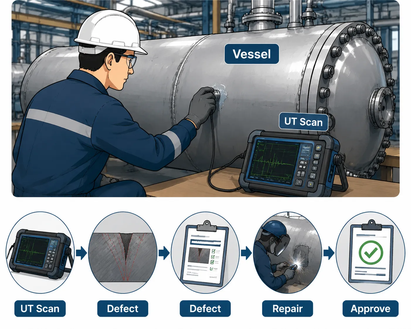
Case Study: Detection of Structural Weakness in Pressure Equipment
Background
A chemical processing company performed routine inspection of a pressure vessel during maintenance.
NDT Examination
The inspection team used:
Ultrasonic Testing.
Visual Inspection.
Radiographic Testing.
Finding
Ultrasonic testing identified reduced wall thickness caused by internal corrosion.
Evaluation
The QA/QC team analysed:
Remaining material thickness.
Operating pressure.
Safety requirements.
Equipment condition.
Corrective Action
The company:
Repaired the affected area.
Reduced corrosion risk.
Increased inspection frequency.
Updated maintenance procedures.
Outcome
The pressure vessel returned to safe operation with improved reliability.
Key Benefits of Accurate NDT Result Interpretation
Effective interpretation provides:
Early defect identification.
Improved safety.
Reduced equipment failure.
Better maintenance planning.
Increased reliability.
Lower repair costs.
Compliance with standards.
Improved decision-making.
Extended equipment life.
Better quality control.
Key Takeaways
NDT interpretation converts inspection data into quality decisions.
Indications must be evaluated before being classified as defects.
Different NDT methods produce different types of results.
Cracks, voids, corrosion, and weaknesses require careful analysis.
Acceptance criteria determine whether components are approved.
QA/QC Mechanical Engineers play a key role in defect evaluation.
Accurate NDT interpretation improves safety and reliability.
Conclusion
Interpreting NDT results is an essential responsibility within mechanical engineering quality control. Through accurate analysis of signals, images, and inspection indications, QA/QC Mechanical Engineers can identify cracks, voids, corrosion, and other structural weaknesses before they lead to equipment failure.
Effective NDT interpretation requires technical knowledge, understanding of inspection methods, and professional judgement. By evaluating defects against engineering specifications and international standards, engineers ensure that mechanical components remain safe, reliable, and suitable for operation. Accurate interpretation of NDT results ultimately supports preventive maintenance, reduces operational risks, and improves the overall quality and performance of mechanical engineering systems.