
Lesson 7: Document inspection findings in line with international QA/QC standards.
Documenting inspection findings accurately and consistently is an essential part of effective Quality Assurance and Quality Control (QA/QC). This lesson, “Document Inspection Findings in Line with International QA/QC Standards,” focuses on the principles and practices required to record inspection results in a clear, objective, complete, and traceable manner. Proper inspection documentation provides reliable evidence that materials, components, equipment, fabrication activities, installation work, and completed processes have been inspected against approved specifications, drawings, procedures, codes, and acceptance criteria.
The lesson explores how to record inspection observations, measurements, test results, non-conformities, defects, corrective actions, photographs, inspection checklists, and supporting evidence in professionally controlled quality records. Learners will understand the importance of accurate descriptions, document identification, revision control, traceability, objective language, and consistent reporting practices. The content also explains how well-prepared inspection records support communication between inspectors, QA/QC personnel, engineers, contractors, clients, and project management teams while providing dependable evidence for quality verification and audit activities.
By completing this lesson, learners will understand how inspection findings should be documented in accordance with applicable international QA/QC requirements, project specifications, inspection and test plans, approved procedures, and contractual requirements. They will develop the ability to produce inspection records that are accurate, auditable, traceable, and suitable for demonstrating conformity or identifying areas requiring corrective action. These skills are particularly relevant to QA/QC inspectors, welding and piping inspectors, construction quality professionals, engineering personnel, fabrication teams, and others responsible for maintaining reliable quality records.
1: Establish Advanced Documentation Systems That Comply with International QA/QC Electrical Standards
Establishing an advanced documentation system is a fundamental responsibility within electrical Quality Assurance and Quality Control (QA/QC). Electrical projects generate extensive technical information throughout their lifecycle, including engineering drawings, specifications, material approvals, inspection requests, testing records, commissioning documents, non-conformance reports, corrective action records, calibration certificates, and final handover documentation. These records provide objective evidence that electrical work has been planned, installed, inspected, tested, verified, and accepted against defined requirements.
An effective electrical QA/QC documentation system is much more than a collection of forms and certificates. It is a controlled framework that connects design requirements with procurement, construction, inspection, testing, commissioning, and handover. The system establishes how documents are prepared, reviewed, approved, issued, revised, distributed, stored, retrieved, protected, and retained. It should allow a competent reviewer or auditor to trace an electrical installation from the original requirement through the approved design and installation activities to inspection findings, test results, corrective actions, and final acceptance.
For international electrical projects, documentation should be developed around the requirements applicable to the specific project. These may include ISO 9001 quality management principles, applicable IEC standards, national electrical regulations, client specifications, contractual requirements, approved drawings, project quality plans, inspection and test plans (ITPs), approved method statements, manufacturer instructions, technical data sheets, and commissioning requirements. An international QA/QC approach does not mean applying one standard to every electrical installation. Instead, the QA/QC professional must identify the standards, regulations, specifications, codes, and contractual requirements applicable to the particular project, jurisdiction, electrical system, equipment, and scope of work.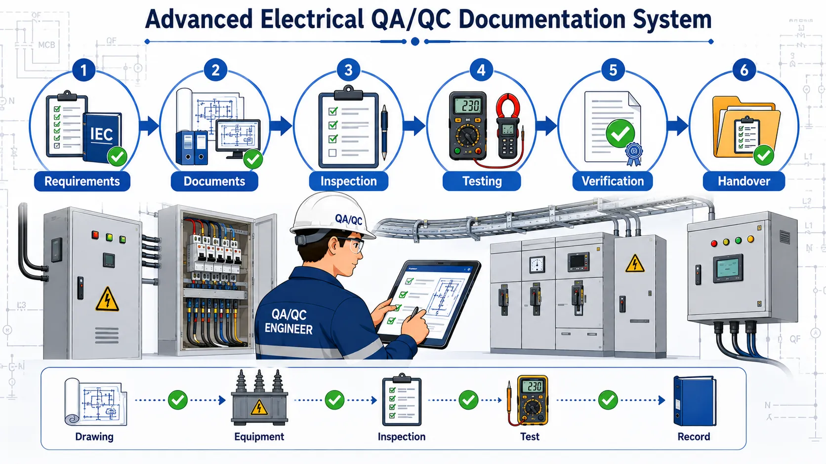
Meaning of an Advanced Electrical QA/QC Documentation System
An advanced electrical QA/QC documentation system is an organised and controlled framework used to create, manage, verify, approve, distribute, retain, and retrieve documents and records associated with electrical quality activities.
The system should provide a complete evidence trail showing:
What requirement applied.
Which drawing or specification controlled the work.
Which materials or equipment were used.
Who performed the work.
Who inspected the work.
What inspection was completed.
What tests were performed.
What results were obtained.
Which instruments were used where applicable.
Whether the results met acceptance criteria.
What non-conformities were identified.
What corrective actions were implemented.
Who verified the corrective actions.
Which documents were finally approved.
What configuration was ultimately handed over.
A basic documentation system may record individual inspections and tests. An advanced system establishes relationships between these records. For example, a distribution board inspection can be linked to its approved technical submittal, manufacturer documentation, equipment identification number, approved drawing, installation inspection, cable termination inspection, test certificate, commissioning record, NCR history, corrective action, and final acceptance record.
This integrated approach provides traceability and makes the quality record useful throughout the complete asset lifecycle.
Relationship Between Quality Assurance and Quality Control Documentation
Quality Assurance and Quality Control have different but closely connected purposes. QA focuses primarily on establishing planned systems, procedures, controls, responsibilities, and processes that create confidence that quality requirements will be achieved. QC focuses on inspection, measurement, testing, examination, and verification of completed or ongoing work.
The documentation system connects these two functions.
For example, the QA process may establish an approved electrical Inspection and Test Plan. The QC team then uses the ITP to perform inspections and tests. The resulting inspection reports, test certificates, photographs, checklists, and NCRs become objective evidence that the QA system has been implemented.
| Key Term | Definition | Electrical QA/QC Application |
|---|---|---|
| Quality Assurance | Planned and systematic activities used to provide confidence that quality requirements will be achieved. | Establishing quality plans, procedures, ITPs, audits, and document controls. |
| Quality Control | Operational activities used to verify that work meets specified requirements. | Inspecting electrical installations and recording test results. |
| Inspection Record | Controlled evidence showing that an inspection was completed and findings were recorded. | Cable, containment, panel, equipment, or installation inspection. |
| Test Record | Controlled evidence of measurements or tests performed against defined requirements. | Insulation resistance, continuity, functional and equipment testing. |
| Inspection and Test Plan | A planned document identifying inspection and testing activities, responsibilities, stages, and acceptance requirements. | Establishing electrical hold points, witness points, inspections, and tests. |
| Non-Conformance Report | A controlled record identifying work or output that does not meet a specified requirement. | Recording defective installation, incorrect material, failed test, or other non-conforming condition. |
| Traceability | The ability to follow the history, location, status, and evidence associated with an item or activity. | Linking equipment to drawings, inspections, tests, certificates, and acceptance. |
| Calibration Record | Evidence that measurement equipment has been appropriately calibrated or verified where required. | Supporting confidence in electrical test measurements. |
| As-Built Record | Controlled documentation representing the final approved installed configuration. | Recording final cable routes, equipment locations, panel arrangements, and approved changes. |
Identifying Applicable International Electrical Requirements
The first stage in establishing an advanced documentation system is to identify the requirements that govern the electrical work.
The QA/QC engineer should review the project contract, specifications, design information, applicable regulations, client requirements, standards, equipment documentation, and inspection requirements before establishing inspection and testing documentation.
Potential sources of requirements include:
ISO 9001 quality management requirements.
Applicable IEC standards.
Applicable national electrical codes.
Local statutory requirements.
Client electrical specifications.
Employer’s requirements.
Approved engineering drawings.
Single-line diagrams.
Equipment specifications.
Manufacturer installation instructions.
Approved technical submittals.
Project quality plans.
Inspection and Test Plans.
Approved method statements.
Testing procedures.
Commissioning procedures.
Contractual acceptance requirements.
Fire and life-safety requirements where applicable.
Equipment certification requirements.
The applicable requirements should be captured in a controlled register. The register should identify the document, revision, approval status, applicable discipline, and location or activity to which it applies.
This prevents personnel from relying on outdated standards, superseded drawings, uncontrolled specifications, or obsolete inspection forms.
Establishing a Controlled Document Hierarchy
A strong documentation system should have a defined hierarchy. This allows personnel to understand the relationship between regulatory requirements, engineering information, construction documentation, inspection records, and final handover information.
Regulatory and Contractual Documents
These may establish the overall requirements for the project, including:
Laws and regulations.
Applicable electrical codes.
Client requirements.
Contract conditions.
Approved standards.
Authority requirements.
Employer’s technical specifications.
Engineering Documents
Engineering documentation may include:
Electrical design drawings.
Single-line diagrams.
Schematic diagrams.
Load schedules.
Cable schedules.
Panel schedules.
Protection studies.
Earthing designs.
Lighting layouts.
Power layouts.
Control schematics.
Equipment specifications.
Technical calculations.
Construction and QA/QC Documents
These commonly include:
Project quality plans.
Inspection and Test Plans.
Method statements.
Material inspection records.
Work inspection requests.
Inspection checklists.
Testing procedures.
Test certificates.
Site observation reports.
NCRs.
Corrective action records.
Punch-list records.
Completion and Handover Documents
Final records may include:
Approved as-built drawings.
Final inspection records.
Electrical test certificates.
Commissioning records.
Equipment certificates.
Calibration records where required.
NCR close-out documentation.
Punch-list close-out records.
Operation and maintenance information.
Final quality dossiers.
This hierarchy provides a logical connection between requirements, design, construction, inspection, testing, correction, acceptance, and handover.
Establishing Document Identification and Numbering
Every controlled document should have a unique identification reference. Document numbering should be consistent across the project and should allow users to determine the document type and location quickly.
A project may establish a numbering structure based on:
Project code.
Discipline.
Document type.
System.
Location.
Sequential number.
Revision.
For example, an electrical inspection document may contain a project identifier, electrical discipline code, inspection category, area reference, and sequential number.
A controlled numbering system should:
Prevent duplicate document numbers.
Support electronic searching.
Simplify document retrieval.
Support revision control.
Facilitate audits.
Allow clear document classification.
Remain consistent across contractors and subcontractors.
The exact numbering methodology should be established within the project’s approved document control procedure.
Developing Standard Electrical Inspection and Test Records
Inspection and test records should be directly connected to the approved ITP and relevant technical requirements.
The ITP should identify:
Inspection activity.
Testing activity.
Responsible organisation.
Inspection stage.
Acceptance criteria.
Required documentation.
Hold points where applicable.
Witness points where applicable.
Verification responsibilities.
Required records.
Electrical inspection activities may include:
Verification of approved materials.
Cable tray inspection.
Cable ladder inspection.
Conduit installation inspection.
Cable installation inspection.
Cable identification inspection.
Cable termination inspection.
Distribution board inspection.
Switchboard inspection.
Switchgear inspection.
Earthing and bonding inspection.
Lighting installation inspection.
Generator installation inspection.
Transformer installation inspection.
Motor installation inspection.
Control panel inspection.
Equipment installation inspection.
Electrical testing may include, depending on system requirements:
Continuity testing.
Insulation resistance testing.
Polarity verification.
Earth continuity testing.
Earthing system measurements.
Functional testing.
Protective device verification.
Equipment-specific testing.
Control circuit testing.
Communication interface testing.
Commissioning tests.
Each inspection or test record should contain enough information to demonstrate what was inspected or tested, which requirement was applied, what results were obtained, and whether the acceptance criteria were satisfied.
Essential Information in Electrical Inspection Records
A professional inspection record should normally contain:
Project name.
Project location.
Inspection reference number.
Inspection date.
Work area.
System identification.
Equipment identification.
Drawing reference.
Drawing revision.
Applicable specification.
Inspection activity.
Acceptance criteria.
Inspection findings.
Measurements where applicable.
Test results where applicable.
Inspection status.
Identified deficiencies.
Photographic references where required.
Inspector identification.
Contractor representative.
Client or consultant representative where applicable.
Corrective action requirements.
Re-inspection status.
Approval status.
Inspection findings should be factual, specific, and objective.
For example, a statement such as “installation is poor” provides insufficient technical information. A stronger record identifies the exact location, equipment, condition observed, applicable requirement, and required action.
A professional finding might identify that a particular cable termination does not correspond with the approved termination arrangement shown on the applicable drawing revision. This provides a clear basis for corrective action and subsequent verification.
Implementing Revision and Change Control
Electrical design information frequently changes during construction. Changes may result from coordination, equipment availability, site conditions, client instructions, design development, or approved engineering modifications.
Without revision control, personnel may continue using obsolete drawings or specifications.
An effective revision control system should ensure that:
Revised documents are technically reviewed.
Required approvals are obtained.
New revisions are clearly identified.
Superseded documents are withdrawn from points of use.
Current documents are distributed to authorised personnel.
Revision histories are maintained.
Affected personnel are informed.
Inspection records reference the correct revision.
As-built records reflect approved changes.
Document Revision Process
A controlled process can include:
Identify the need for change.
Prepare the revised document.
Review the technical change.
Assess impacts on related documents.
Obtain required approvals.
Assign the new revision.
Update the document register.
Issue the revised document.
Withdraw or identify superseded versions.
Communicate the change.
Verify implementation where necessary.
Maintain the revision history.
Particular attention should be given to changes affecting cable sizes, protection settings, equipment ratings, load requirements, earthing arrangements, circuit configurations, control systems, or safety-related electrical systems.
Establishing Electrical Material and Equipment Traceability
Traceability allows QA/QC personnel to follow an item from procurement and approval through installation, inspection, testing, commissioning, and acceptance.
For example, a distribution board can be traced through:
Approved material submittal.
Manufacturer information.
Purchase documentation.
Delivery inspection.
Equipment identification.
Serial number.
Installation inspection.
Cable termination inspection.
Test results.
Commissioning record.
NCR history.
Corrective action.
Final acceptance.
As-built documentation.
Important traceability information may include:
Manufacturer.
Model.
Serial number.
Equipment identification number.
Rating.
Location.
Material certificate where applicable.
Inspection status.
Installation date.
Test status.
Certification information.
Traceability is particularly valuable for major, safety-critical, high-value, or technically complex electrical equipment.
Integrating Test Equipment and Calibration Records
Electrical QA/QC relies heavily on measurement and testing. The reliability of a test result depends partly on the suitability and control of the instrument used.
Where project procedures require calibration or verification, the documentation system should link the test record with the relevant instrument identification.
Controlled information may include:
Instrument identification number.
Manufacturer.
Model.
Serial number.
Measurement capability.
Calibration status.
Calibration date.
Calibration due date.
Calibration certificate.
Equipment condition.
User or responsible department.
Typical electrical test instruments may include:
Digital multimeters.
Insulation resistance testers.
Earth resistance testers.
Clamp meters.
Phase sequence testers.
Electrical safety testers.
Power quality analysers.
Specialist commissioning equipment.
High-voltage testing equipment where applicable.
Where traceability is required, the instrument identification should be recorded on the test certificate so that the measurement can be reviewed and verified later.
Managing Electrical Non-Conformities
An advanced documentation system must include an effective process for identifying, recording, controlling, correcting, and closing non-conformities.
Potential electrical non-conformities include:
Incorrect equipment rating.
Installation contrary to approved drawings.
Unapproved material.
Incorrect cable identification.
Incorrect termination.
Failed electrical test.
Inadequate earthing or bonding installation.
Incorrect equipment location.
Missing inspection evidence.
Incomplete installation.
Unapproved design change.
Missing certification.
A controlled NCR process should include:
Identification of the non-conformity.
Recording of objective evidence.
Identification of the applicable requirement.
Assessment of the condition.
Proposed disposition.
Technical review where necessary.
Approval of corrective action.
Implementation.
Re-inspection or re-testing.
Verification of effectiveness.
Formal closure.
Record retention.
An NCR should clearly establish the relationship between the observed condition and the requirement that has not been satisfied.
Electronic Electrical QA/QC Documentation
Modern electrical projects increasingly use electronic document management systems. Digital systems can significantly improve document accessibility and traceability when appropriately controlled.
Potential capabilities include:
Document version control.
Controlled access.
Electronic approval.
Audit trails.
Document registers.
Inspection workflows.
NCR tracking.
Mobile inspection forms.
Photographic attachments.
Automated notifications.
Search and filtering.
Record indexing.
Centralised storage.
Backup and recovery.
For example, a field inspector may use a controlled digital checklist to inspect a distribution board, access the latest approved drawing, record findings, attach photographs, identify a non-conformity, and submit the inspection through a controlled workflow.
However, digitalisation alone does not guarantee quality. The organisation must still establish appropriate responsibilities, access controls, approval workflows, revision management, data integrity requirements, retention periods, and backup procedures.
Protecting Documentation Integrity
Electrical QA/QC records may become important contractual, safety, regulatory, operational, or legal evidence. Their integrity must therefore be protected.
Controls may include:
User authentication.
Role-based permissions.
Controlled editing rights.
Audit trails.
Electronic approval workflows.
Revision histories.
Secure backups.
Access restrictions.
Record retention controls.
Protection against unauthorised deletion.
Controlled distribution.
Periodic system audits.
Personnel should understand that unauthorised modification of an approved inspection or test record can undermine the reliability of the entire quality record.
Procedure for Establishing an Advanced Electrical Documentation System
The QA/QC engineer can establish the system through a structured process.
Step 1: Review Project Requirements
Identify all applicable:
Contract requirements.
Client specifications.
Regulations.
Standards.
Drawings.
Quality requirements.
Testing requirements.
Handover requirements.
Step 2: Develop a Controlled Document Register
The register should contain:
Document number.
Document title.
Revision.
Status.
Responsible party.
Approval status.
Issue date.
Distribution information.
Step 3: Develop Standard Templates
Prepare controlled templates for:
Inspection requests.
Material inspection reports.
Electrical checklists.
Test records.
Commissioning records.
NCRs.
Corrective action reports.
Site observations.
Punch lists.
Handover records.
Step 4: Define Responsibilities
Clearly establish who is responsible for:
Preparation.
Checking.
Technical review.
Approval.
Issue.
Inspection.
Verification.
Closure.
Step 5: Link Documentation With the ITP
Every inspection and testing activity should have defined:
Acceptance criteria.
Responsible personnel.
Inspection stage.
Hold or witness requirements where applicable.
Required evidence.
Required record.
Step 6: Establish Traceability
Connect equipment and installation records with:
Approved drawings.
Materials.
Serial numbers.
Inspection records.
Test results.
NCRs.
Corrective actions.
Final acceptance.
Step 7: Implement Revision Control
Ensure only current and approved documents are available at the point of use.
Step 8: Establish Retention Requirements
Define:
Which records must be retained.
Required retention periods.
Storage arrangements.
Access controls.
Backup arrangements.
Handover requirements.
Step 9: Audit the Documentation System
Regularly verify that:
Current documents are being used.
Inspection records are complete.
Test records are traceable.
NCRs are properly closed.
Revision control is effective.
Records can be retrieved.
Step 10: Apply Continual Improvement
Use:
Audit findings.
Recurring NCRs.
Documentation errors.
Project lessons learned.
User feedback.
Handover issues.
to improve the documentation system.
Practical Example: Electrical Distribution Installation
Consider a commercial building project involving distribution boards, power cables, cable containment, lighting systems, emergency electrical systems, control circuits, and earthing and bonding.
Before construction begins, the Electrical QA/QC Engineer establishes a controlled document system. Approved electrical drawings are entered into the document register. Each drawing has a unique number, revision, status, and approval reference. The ITP identifies containment inspection, cable installation inspection, termination inspection, equipment inspection, electrical testing, and commissioning activities.
During construction, inspectors use approved inspection forms. Each inspection record identifies the work location, system, equipment, drawing reference, drawing revision, inspection activity, acceptance criteria, and findings. Photographs are attached where required.
During inspection, an incorrectly identified cable is discovered. Instead of recording only “cable label incorrect,” the inspector records the cable reference, location, drawing reference, observed identification, required identification, and applicable requirement. An NCR is raised.
The contractor corrects the identification. The QA/QC inspector performs a follow-up inspection and verifies the correction. The NCR is closed only after the corrective action has been objectively verified.
At completion, the quality dossier provides traceable evidence showing:
Approved design information.
Approved materials.
Installation inspections.
Electrical test results.
Calibration information where required.
Non-conformities.
Corrective actions.
Final inspections.
Commissioning results.
Approved as-built information.
This demonstrates how a documentation system transforms individual inspection activities into a structured and auditable quality evidence trail.
Case Study: Documentation Failure During Electrical Project Handover
Project Background
A large industrial facility was approaching electrical commissioning and final handover. The installation included switchboards, motor control equipment, power cabling, lighting systems, control circuits, emergency systems, and earthing infrastructure.
The physical construction work was substantially complete, but the documentation had been developed inconsistently by several subcontractors.
Problems Identified
During the final QA/QC review, the team identified:
Different inspection forms being used.
Missing drawing revision references.
Incomplete equipment identification.
Test records with unclear equipment references.
Inadequate instrument identification.
Open NCRs without documented verification.
Missing inspection evidence.
Conflicting as-built information.
The physical installation appeared largely satisfactory, but the project could not consistently demonstrate conformity through objective records.
Corrective Action
The QA/QC management team introduced a documentation recovery programme.
The programme included:
Establishing a master document register.
Identifying current approved drawing revisions.
Standardising inspection forms.
Reviewing existing inspection records.
Linking equipment identification with test certificates.
Reviewing open NCRs.
Repeating selected inspections where evidence was inadequate.
Reviewing test certificates.
Establishing document approval workflows.
Updating as-built documentation.
Performing a final documentation audit.
Outcome
The project developed a more reliable handover dossier because each major electrical system had a traceable evidence trail.
The case demonstrates an important professional principle: satisfactory physical installation alone does not necessarily demonstrate conformity. Quality must also be supported by reliable inspection, testing, approval, and traceability records.
Key Benefits of an Advanced Electrical QA/QC Documentation System
Improved Traceability
An effective system:
Links work to approved requirements.
Identifies responsible personnel.
Connects equipment with inspection evidence.
Supports quality investigations.
Simplifies audit preparation.
Supports lifecycle maintenance.
Improved Quality Control
It also:
Standardises inspection processes.
Reduces missing records.
Improves defect identification.
Supports corrective action.
Provides evidence of testing.
Improves final verification.
Improved Project Management
A controlled system:
Provides inspection status visibility.
Identifies outstanding records.
Supports construction completion.
Improves coordination.
Supports commissioning.
Strengthens project handover.
Reduced Technical and Contractual Risk
Documentation controls can:
Reduce reliance on undocumented information.
Minimise obsolete drawing use.
Improve equipment traceability.
Support safety-related verification.
Provide objective evidence during disputes.
Support regulatory and client reviews.
Improved Auditing
A well-structured system enables:
Faster document retrieval.
Reliable revision history.
Objective evidence.
Better NCR tracking.
Clear approval records.
More effective internal and external audits.
Common Documentation Failures to Avoid
Electrical QA/QC professionals should avoid:
Using uncontrolled forms.
Failing to reference drawing revisions.
Recording vague findings.
Omitting equipment identification.
Failing to identify test instruments where required.
Using uncontrolled test records.
Closing NCRs without verification.
Keeping obsolete documents at points of use.
Allowing unauthorised document modification.
Creating records retrospectively without reliable supporting evidence.
Using inconsistent terminology.
Omitting acceptance criteria.
Failing to maintain revision history.
Losing supporting photographs.
Providing incomplete handover records.
Weak electronic access controls.
Failing to back up critical quality records.
The objective should not be to produce excessive paperwork. The objective is to create relevant, accurate, controlled, retrievable, and technically meaningful evidence.
Professional Responsibilities of the Electrical QA/QC Engineer
The Electrical QA/QC Engineer has a central responsibility for establishing and maintaining the documentation framework.
Professional responsibilities may include:
Reviewing project quality requirements.
Identifying applicable electrical standards.
Reviewing specifications and drawings.
Developing electrical ITPs.
Establishing inspection documentation.
Controlling document revisions.
Reviewing inspection records.
Reviewing electrical test documentation.
Monitoring NCR processes.
Checking equipment traceability.
Reviewing calibration evidence where applicable.
Supporting internal and external audits.
Reviewing handover dossiers.
Training inspection personnel.
Monitoring recurring documentation weaknesses.
Supporting continual improvement.
The QA/QC Engineer should also ensure that documentation requirements are proportionate to project risk. Excessive documentation that does not support meaningful verification can increase administrative burden, while insufficient documentation can create significant quality and contractual risks. The most effective approach is to establish controlled records that provide clear evidence of important quality decisions and verification activities.
Key Learning Points
By completing this part, learners should understand that:
Electrical QA/QC documentation is a technical quality control mechanism.
Applicable international and national requirements must be identified for the specific project.
Documentation should be based on approved project requirements.
Document registers support controlled information management.
Revision control prevents the use of obsolete technical information.
Inspection records should contain objective and traceable evidence.
Test records should clearly identify the equipment and applicable results.
Measuring equipment should be appropriately controlled where required.
NCRs should clearly identify non-conforming conditions and applicable requirements.
Corrective actions should be verified before NCR closure.
Electronic systems can improve document accessibility and traceability.
As-built documentation should represent the final approved installation.
Quality records require appropriate protection against unauthorised changes or loss.
Documentation supports audits, commissioning, handover, maintenance, and future investigations.
A strong documentation system connects QA planning with QC inspection and testing.
Effective records provide objective evidence of electrical conformity.
Conclusion
Establishing an advanced documentation system is an essential professional competency for electrical QA/QC personnel working on complex construction, industrial, infrastructure, commercial, energy, and engineering projects. The documentation system should create a controlled connection between applicable standards, regulations, contractual requirements, engineering design, procurement, installation, inspection, testing, non-conformance management, corrective action, commissioning, and final handover.
An effective system depends on clear document identification, controlled revisions, traceability, standardised inspection and test records, appropriate control of measuring equipment, structured NCR management, secure record storage, defined responsibilities, and effective approval processes. It should enable an organisation to demonstrate not only that electrical work was completed, but also that the work was inspected, tested, evaluated against appropriate acceptance criteria, corrected where necessary, and formally accepted.
For an Electrical QA/QC Engineer, documentation is therefore not merely an administrative responsibility. It is a core component of quality management and technical assurance. Accurate and controlled records provide objective evidence that supports compliance, safety, contractual acceptance, auditing, commissioning, maintenance, and continual improvement. When documentation is integrated properly into the electrical QA/QC process, it becomes a powerful tool for controlling quality throughout the complete project and asset lifecycle.
2: Record Complex Inspection and NDE Findings Accurately Using Structured, Professional Reporting Formats
Recording complex inspection and Non-Destructive Examination (NDE) findings accurately is a critical responsibility within electrical QA/QC, engineering inspection, fabrication, maintenance, construction, and asset integrity management. Inspection and NDE activities generate technical evidence about the condition, conformity, integrity, and serviceability of electrical equipment, components, connections, structures, welds, cables, containment systems, and associated infrastructure. When these findings are recorded incorrectly, incompletely, or inconsistently, the value of the inspection itself can be significantly reduced. A technically competent inspection that produces a poorly structured report may fail to provide sufficient evidence for engineering decisions, corrective actions, audits, client acceptance, maintenance planning, or future investigations.
Professional inspection reporting therefore requires much more than writing down observations. The inspector must understand the inspection objective, identify the item examined, establish the applicable acceptance criteria, record the inspection method and conditions, document relevant measurements and indications, distinguish observations from interpretations, and clearly communicate whether the examined item conforms to the specified requirements. Where NDE is involved, the report should also identify the NDE method, equipment, procedure, examiner or technician, relevant parameters, limitations, indications detected, evaluation criteria, and final disposition where applicable.
In international electrical QA/QC environments, inspection and NDE reporting should be integrated with the project’s approved quality management system, Inspection and Test Plan (ITP), specifications, drawings, codes, standards, procedures, manufacturer requirements, contractual conditions, and applicable regulatory requirements. Depending on the nature of the work, NDE may include methods such as visual testing, ultrasonic testing, radiographic testing, magnetic particle testing, liquid penetrant testing, eddy current testing, thermographic inspection, or other approved examination techniques. The applicable method and reporting requirements should always be determined by the relevant specification, procedure, equipment requirements, and governing standard rather than selected arbitrarily.
Meaning of Complex Inspection and NDE Findings
Complex inspection findings are observations or results that require technical interpretation, comparison with defined acceptance criteria, and structured reporting. They may involve multiple measurements, inspection locations, equipment identifiers, drawings, test parameters, photographs, indications, previous inspection records, or related quality documents.
An NDE finding may be described as an indication detected through an approved examination method. The indication may or may not represent a rejectable defect. This distinction is important because professional reporting should not automatically classify every indication as a defect.
For example, an ultrasonic examination may identify an indication within a component. The inspector or qualified examiner must evaluate the indication against the applicable procedure and acceptance criteria before determining its significance.
Similarly, thermographic inspection of an electrical distribution system may identify an abnormal temperature pattern. The report should record the measured temperature, reference temperature or comparable condition, equipment identification, load condition, inspection distance where relevant, environmental conditions where relevant, and applicable evaluation criteria. Simply stating “panel overheating” would not provide sufficient technical evidence.
Complex findings may therefore involve:
- Multiple inspection techniques.
- Multiple inspection locations.
- Several measurements.
- Different acceptance criteria.
- Equipment-specific requirements.
- Drawings and specifications.
- Photographic evidence.
- NDE indications.
- Previous inspection results.
- Corrective action history.
- Re-inspection results.
- Engineering evaluation.
The purpose of structured reporting is to convert this technical information into reliable quality evidence that can be understood and acted upon by competent personnel.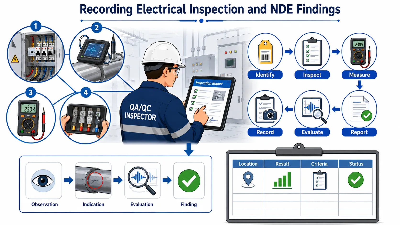
Difference Between an Observation, Indication, Defect and Non-Conformance
A professional inspector should understand the difference between these terms.
An observation is a condition identified during inspection. It does not necessarily mean that the condition is unacceptable.
An indication is a response or signal identified by an NDE method. It requires evaluation according to the applicable examination procedure and acceptance criteria.
A defect is a condition that has been determined to be unacceptable under the applicable requirements.
A non-conformance is a failure to meet a specified requirement and may relate to installation, documentation, materials, workmanship, testing, equipment, or another controlled requirement.
These terms should not be used interchangeably.
For example:
- “Surface indication observed” describes an inspection finding.
- “Indication evaluated as relevant” provides further technical interpretation.
- “Indication exceeds specified acceptance limit” establishes non-acceptance.
- “NCR raised” records the quality management response.
This structured progression helps prevent unsupported conclusions and improves the technical reliability of the report.
Key Concepts in Professional Inspection and NDE Reporting
Accuracy
Accuracy means recording inspection information correctly and without introducing errors.
The report should accurately represent:
- Equipment identification.
- Inspection location.
- Date and time where relevant.
- Inspection method.
- Measurement results.
- NDE parameters.
- Indication location.
- Indication dimensions where applicable.
- Acceptance criteria.
- Inspection status.
- Corrective action status.
Numerical values should be transferred carefully from instruments, examination records, or approved data sheets. Units must be clearly stated.
For example, recording a temperature as “85” without identifying whether the unit is °C or °F creates ambiguity. Similarly, a cable resistance result should clearly identify the measurement unit and test conditions.
Objectivity
Inspection reporting should be based on observable evidence rather than personal opinion.
Avoid vague expressions such as:
- Poor workmanship.
- Looks unsafe.
- Very bad condition.
- Probably defective.
- Seems acceptable.
- Operator mistake.
Instead, describe the actual condition.
For example:
- “Cable gland is not fully engaged with the enclosure entry.”
- “Thermal image indicates elevated temperature at the identified termination compared with adjacent phases.”
- “Surface indication detected at the specified examination location.”
- “Measured value exceeds the project acceptance criterion.”
Objective wording allows another competent person to understand the finding without relying on the original inspector’s assumptions.
Traceability
Traceability enables a finding to be connected with the exact item and location examined.
Traceability may involve:
- Equipment tag number.
- Cable identification.
- Panel number.
- Circuit number.
- Drawing reference.
- Drawing revision.
- Work package.
- Inspection reference.
- NDE report number.
- Test certificate number.
- Material identification.
- Serial number.
- Location reference.
Without adequate traceability, even a technically accurate finding may be difficult to use.
Completeness
A report should contain enough information for a competent reviewer to understand:
- What was inspected.
- Why it was inspected.
- How it was inspected.
- Where it was inspected.
- What was found.
- What criteria were applied.
- What the results mean.
- What action is required.
Completeness does not mean unnecessarily long reports. It means including all information necessary to establish reliable evidence.
Consistency
Structured formats should use consistent terminology, units, numbering, acceptance criteria, and status categories.
Consistency helps:
- Compare inspection results.
- Identify recurring defects.
- Analyse trends.
- Support audits.
- Reduce interpretation errors.
- Improve reporting efficiency.
Structured Inspection Reporting Format
A professional inspection or NDE report should follow a defined structure.
1. Report Identification
The first section should establish the identity of the report.
Typical information includes:
- Project name.
- Project number.
- Client.
- Contractor.
- Inspection organisation.
- Report number.
- Inspection date.
- Revision number.
- Inspection status.
The report number should be unique and controlled.
2. Item Identification
The inspected item should be clearly identified.
This may include:
- Equipment tag.
- Asset number.
- Component number.
- Panel number.
- Cable number.
- Circuit reference.
- Serial number.
- Location.
- System identification.
- Drawing reference.
Where multiple items are inspected, each item should be individually traceable.
3. Inspection Scope
The report should clearly explain what was examined.
The scope may identify:
- Equipment inspected.
- Components examined.
- Inspection boundaries.
- Inspection locations.
- Examination percentage.
- Sampling requirements.
- Inspection purpose.
For example, the report may state that visual examination was performed on specified cable terminations within a defined electrical room, or that thermographic inspection covered identified distribution equipment under an agreed operating load.
4. Applicable Documents and Criteria
The report should identify the requirements against which the findings are evaluated.
These may include:
- Approved drawings.
- Project specifications.
- Inspection procedures.
- ITP requirements.
- Manufacturer instructions.
- Applicable codes.
- Applicable standards.
- Acceptance criteria.
- Approved method statements.
The exact reference and revision should be recorded where required.
5. Inspection Method
The report should identify the inspection or NDE technique used.
Examples include:
- Visual Testing (VT).
- Ultrasonic Testing (UT).
- Radiographic Testing (RT).
- Magnetic Particle Testing (MT).
- Liquid Penetrant Testing (PT).
- Eddy Current Testing (ET).
- Infrared Thermography.
- Electrical measurement and testing.
- Equipment-specific diagnostic methods.
The report should not imply that a particular NDE method was suitable unless it was approved for the relevant application.
6. Equipment and Instrument Information
Where applicable, identify:
- Instrument manufacturer.
- Instrument model.
- Serial number.
- Equipment identification.
- Calibration status.
- Calibration certificate.
- Probe or sensor information.
- Relevant accessories.
This information supports measurement traceability.
7. Inspection Conditions
Some inspection findings depend strongly on inspection conditions.
Relevant conditions may include:
- Ambient temperature.
- Equipment operating temperature.
- Electrical load.
- Environmental conditions.
- Surface condition.
- Accessibility.
- Lighting.
- Inspection distance.
- Equipment operating state.
- Preparation condition.
For electrical thermography, for example, the operating load can be important when interpreting thermal patterns.
Recording NDE Findings
NDE findings should be documented in a way that allows the indication to be located, understood, evaluated, and verified.
NDE Method and Procedure
The report should identify:
- NDE method.
- Approved procedure.
- Procedure revision.
- Examination technique.
- Examination area.
- Examination extent.
- Relevant equipment.
- Examiner identification where required.
This allows reviewers to determine whether the examination was performed under controlled conditions.
Location of the Indication
The location should be sufficiently precise to permit re-examination.
Possible references include:
- Component coordinates.
- Weld identification.
- Distance from a reference point.
- Equipment tag.
- Cable location.
- Panel position.
- Drawing coordinates.
- Grid reference.
- Physical orientation.
A report should avoid descriptions such as “defect near the end” where the location cannot be reliably identified.
Size and Characteristics
Where relevant and measurable, the report should record:
- Length.
- Width.
- Depth where determinable.
- Orientation.
- Shape.
- Position.
- Number of indications.
- Distance between indications.
- Relevant signal characteristics.
The information recorded should be appropriate to the NDE method and the approved procedure.
Acceptance Evaluation
The report should distinguish between detection and evaluation.
The examiner identifies and characterises an indication according to the applicable procedure. The finding is then evaluated against the applicable acceptance criteria.
Possible outcomes may include:
- Acceptable.
- Requires further evaluation.
- Rejectable.
- Repair required.
- Re-examination required.
- Engineering assessment required.
The report should clearly state the basis for the conclusion.
Recording Electrical Inspection Findings
Although NDE methods are often associated with material and component examination, electrical QA/QC inspection also produces complex findings requiring structured reporting.
Examples include:
- Cable termination defects.
- Loose connections.
- Incorrect cable routing.
- Inadequate gland installation.
- Damaged insulation.
- Incorrect equipment identification.
- Poor earthing or bonding connections.
- Incorrect equipment rating.
- Thermal anomalies.
- Protection setting discrepancies.
- Incomplete enclosure sealing.
- Incorrect phase identification.
- Damaged cable containment.
- Unauthorised modifications.
Each finding should be recorded with enough technical detail to allow corrective action.
For example, a thermal inspection finding should ideally identify:
- Equipment.
- Location.
- Circuit.
- Load condition.
- Measured temperature.
- Comparable temperature.
- Thermal pattern.
- Inspection date.
- Instrument identification.
- Image reference.
- Evaluation criteria.
- Recommended action.
Using Structured Tables for Multiple Findings
When several findings are identified, a structured table can provide better clarity than long narrative paragraphs.
A typical finding register may contain:
| Finding No. | Equipment/Location | Inspection Method | Finding | Acceptance Criteria | Status | Required Action |
|---|---|---|---|---|---|---|
| 01 | DB-04, Phase B | Visual | Loose termination identified | Approved installation requirement | Non-conforming | Rectify and re-inspect |
| 02 | Cable C-17 | Thermography | Elevated termination temperature | Project thermal criterion | Review required | Investigate connection |
| 03 | Panel P-06 | Visual | Missing identification label | Approved labelling specification | Non-conforming | Install correct label |
| 04 | Component X | NDE | Indication detected | Applicable NDE procedure | Evaluation required | Complete technical evaluation |
This format provides a rapid overview while maintaining traceability.
Recording Photographic and Digital Evidence
Photographs can significantly strengthen inspection reports when they are properly controlled.
A useful inspection photograph should:
- Clearly show the inspected item.
- Include sufficient context.
- Identify the location.
- Relate to a specific finding.
- Be linked to the report reference.
- Avoid misleading angles.
- Maintain original evidence where required.
For complex findings, both overview and close-up images may be appropriate.
Digital evidence may also include:
- Thermal images.
- Instrument screenshots.
- Test instrument readings.
- NDE scan images.
- Radiographic images where applicable.
- Ultrasonic scan records.
- Digital inspection forms.
- Equipment photographs.
- Annotated drawings.
Each digital attachment should be uniquely referenced and linked to the relevant inspection record.
Recording Measurement Data Correctly
Measurement results are often central to technical inspection decisions.
The report should identify:
- Measurement value.
- Unit.
- Measurement location.
- Instrument.
- Measurement date.
- Test condition.
- Applicable acceptance limit.
- Result status.
Avoid recording isolated values without context.
For example:
“92”
provides little useful information.
A structured record should establish what was measured, where it was measured, under what conditions, which instrument was used, and what requirement was applied.
Measurement transcription errors can create serious quality problems. Therefore, data should be reviewed before the report is approved.
Handling Uncertain or Incomplete Findings
Not every inspection result immediately leads to a final conclusion.
Sometimes:
- Access is restricted.
- Equipment cannot be de-energised.
- Surface preparation is inadequate.
- The NDE indication requires additional evaluation.
- Required documentation is unavailable.
- Test conditions are not representative.
- An engineering decision is required.
In such circumstances, the report should clearly identify the limitation rather than presenting an unsupported conclusion.
Appropriate reporting may include:
- Inspection incomplete.
- Further examination required.
- Engineering evaluation required.
- Access limitation recorded.
- Retest required.
- Evidence insufficient for final acceptance.
This approach protects the integrity of the inspection record.
Managing Re-Inspection and Corrective Actions
Complex findings often require follow-up.
The reporting system should allow the original finding to remain traceable throughout corrective action.
A typical process includes:
- Record original finding.
- Reference applicable requirement.
- Classify the finding.
- Raise NCR or observation where required.
- Assign responsible party.
- Define corrective action.
- Complete corrective work.
- Perform re-inspection.
- Repeat NDE or testing where required.
- Record new results.
- Compare with original findings.
- Verify conformity.
- Close the finding.
The original record should not simply be deleted or overwritten after correction. The history should remain visible so that the complete quality trail can be demonstrated.
Professional Reporting Language
The language used in inspection reports should be technical, neutral, precise, and evidence-based.
Avoid
- “Looks bad.”
- “Very poor work.”
- “Probably unsafe.”
- “Seems okay.”
- “Worker did it incorrectly.”
- “This is definitely defective.”
Prefer
- “Observed condition does not correspond with the approved drawing.”
- “Measured value exceeds the specified acceptance limit.”
- “Indication requires evaluation against the applicable NDE acceptance criteria.”
- “Inspection could not be completed due to restricted access.”
- “Corrective action is required before final acceptance.”
- “Re-inspection confirmed that the identified condition has been corrected.”
This style improves professional communication and reduces ambiguity.
Process for Recording Complex Inspection and NDE Findings
Step 1: Confirm the Inspection Requirement
Before inspection, identify:
- Scope.
- Applicable specification.
- Approved procedure.
- ITP activity.
- Acceptance criteria.
- Inspection stage.
Step 2: Identify the Item
Confirm:
- Equipment tag.
- Component identification.
- Location.
- Drawing reference.
- Serial number where applicable.
Step 3: Verify Inspection Conditions
Record relevant:
- Operating conditions.
- Environmental conditions.
- Surface condition.
- Accessibility.
- Load conditions.
- Preparation requirements.
Step 4: Perform the Inspection
Use the approved inspection or NDE method.
Do not deviate from the approved procedure without appropriate technical authorisation.
Step 5: Record Raw Findings
Document:
- Measurements.
- Indications.
- Locations.
- Dimensions.
- Images.
- Test results.
- Relevant observations.
Step 6: Evaluate Findings
Compare the results against:
- Acceptance criteria.
- Drawings.
- Specifications.
- Approved procedures.
- Applicable technical requirements.
Step 7: Determine Status
The finding may be:
- Conforming.
- Non-conforming.
- Pending evaluation.
- Requiring further examination.
- Requiring corrective action.
Step 8: Record Required Action
Where necessary:
- Raise NCR.
- Identify corrective action.
- Assign responsibility.
- Establish follow-up requirements.
Step 9: Conduct Verification
After corrective action:
- Re-inspect.
- Re-test.
- Repeat NDE where required.
- Record new results.
Step 10: Approve and Archive
The final report should be:
- Reviewed.
- Approved.
- Assigned final status.
- Stored in the controlled document system.
- Linked with relevant quality records.
Key Benefits of Structured Inspection and NDE Reporting
Improved Technical Accuracy
Structured formats reduce the risk of missing critical information and improve consistency between inspectors.
Improved Traceability
Each finding can be connected to:
- Equipment.
- Location.
- Drawing.
- Inspection.
- Test.
- NDE record.
- NCR.
- Corrective action.
- Final acceptance.
Stronger Audit Evidence
Auditors can verify:
- What was inspected.
- Which procedure was used.
- What was found.
- What acceptance criteria applied.
- How non-conformities were addressed.
Better Corrective Action
Clear findings provide contractors and maintenance teams with sufficient information to understand what needs to be corrected.
Improved Trend Analysis
Consistent reporting enables organisations to identify recurring problems such as:
- Repeated termination defects.
- Frequent equipment installation errors.
- Recurring cable identification problems.
- Repeated NDE indications.
- Frequent documentation failures.
Improved Asset Integrity
Accurate inspection records create a historical record that can support future maintenance, reliability assessments, condition monitoring, and engineering decisions.
Reduced Disputes
Objective records can help establish:
- What condition existed.
- When it was identified.
- Which requirement applied.
- What corrective action was taken.
- Who verified the correction.
Practical Example: Thermographic Inspection of an Electrical Distribution Board
An electrical QA/QC team performs a thermographic inspection of a distribution board during normal operating conditions.
The inspector identifies an elevated temperature at one cable termination compared with adjacent phases.
A poor report might state:
“DB-03 has overheating problem.”
This statement is insufficient because it does not identify the exact component, operating condition, measurement data, instrument, comparison, or acceptance basis.
A structured report should record:
- Distribution board identification.
- Circuit identification.
- Phase identification.
- Inspection date.
- Equipment operating condition.
- Load condition where relevant.
- Thermal image reference.
- Measured temperature.
- Comparable temperature.
- Instrument identification.
- Inspection procedure.
- Applicable evaluation criteria.
- Finding description.
- Status.
- Recommended action.
The finding may then be referred for investigation. If a loose termination is confirmed, corrective action can be performed. A subsequent thermographic inspection can verify whether the condition has been resolved.
This example demonstrates how structured reporting converts a visual observation into objective technical evidence.
Practical Example: NDE Finding Requiring Further Evaluation
An NDE examination identifies an indication within a component.
The inspector records the indication location, examination method, relevant dimensions, and examination conditions. The indication is not immediately classified as rejectable because the applicable acceptance criteria require further evaluation.
The report therefore records:
- Indication detected.
- Exact location.
- Examination method.
- Procedure reference.
- Relevant indication characteristics.
- Examination limitations.
- Evaluation status.
- Requirement for technical review.
Following technical evaluation, the indication may be accepted, repaired, or subjected to additional examination.
This demonstrates why inspection reporting must distinguish between detection and final evaluation.
Case Study: Incomplete NDE Documentation on an Industrial Project
Project Background
An industrial electrical installation project included equipment fabrication, cable systems, electrical enclosures, supporting structures, and associated components requiring inspection and NDE. The contractor had completed numerous examinations, but the quality records were inconsistent.
Some reports contained equipment references but no exact inspection locations. Other reports included findings but did not identify the applicable acceptance criteria. Several reports also contained photographs without clear references to the corresponding inspection record.
Problems Identified
During a QA/QC audit, the following issues were discovered:
- Inconsistent report formats.
- Missing equipment identification.
- Incomplete NDE procedure references.
- Unclear indication locations.
- Missing measurement units.
- Photographs without traceable references.
- Findings without acceptance criteria.
- Corrective actions without verification records.
- Incomplete examiner information.
- Difficulty linking inspection findings to final handover documentation.
Although the inspection activities had been performed, the quality of the evidence was insufficient.
Corrective Strategy
The QA/QC team introduced a standard reporting format requiring:
- Unique report numbers.
- Equipment identification.
- Inspection location.
- NDE method.
- Procedure reference.
- Inspection conditions.
- Instrument information where applicable.
- Finding description.
- Indication characteristics.
- Acceptance criteria.
- Finding status.
- Supporting evidence.
- Corrective action.
- Re-inspection result.
- Final approval.
All previous records were reviewed, and missing information was identified.
Where reliable evidence could not be established from existing documentation, additional inspection or verification was performed where technically appropriate.
Outcome
The revised reporting system created a consistent inspection evidence trail. Findings could be traced to specific equipment and locations, corrective actions could be followed through to closure, and the final quality dossier contained clearer evidence for client review and project handover.
The case demonstrates that inspection quality depends not only on the technical competence of the examination but also on the quality and traceability of the resulting documentation.
Common Errors in Recording Inspection and NDE Findings
QA/QC personnel should avoid:
- Using vague descriptions.
- Omitting equipment identification.
- Failing to record exact inspection locations.
- Recording measurements without units.
- Failing to identify the inspection method.
- Omitting procedure references.
- Failing to identify acceptance criteria.
- Treating every NDE indication as a defect.
- Recording opinions instead of observations.
- Omitting inspection conditions.
- Using uncontrolled report templates.
- Overwriting original findings after correction.
- Failing to link photographs to findings.
- Closing findings without verification.
- Omitting test instrument information where required.
- Using inconsistent terminology.
- Failing to record report revisions.
- Losing supporting digital evidence.
These errors can make otherwise valuable inspection information difficult to verify or defend.
Responsibilities of the Electrical QA/QC Engineer
The Electrical QA/QC Engineer should ensure that inspection and NDE reporting systems are technically appropriate, controlled, and consistently implemented.
Responsibilities may include:
- Developing inspection reporting procedures.
- Reviewing NDE reporting requirements.
- Establishing standard templates.
- Defining required data fields.
- Reviewing inspection findings.
- Checking traceability.
- Verifying acceptance criteria.
- Reviewing NCRs.
- Monitoring corrective actions.
- Auditing inspection records.
- Training inspection personnel.
- Coordinating with engineering teams.
- Supporting client inspections.
- Reviewing final quality dossiers.
- Identifying recurring inspection problems.
- Supporting continual improvement.
The engineer should also ensure that personnel understand the difference between recording a finding and making an engineering decision. Where specialist evaluation is required, the report should identify the need for appropriate technical review rather than making an unsupported conclusion.
Key Learning Points
By completing this part, learners should understand that:
- Complex inspection findings require structured and objective reporting.
- NDE indications should not automatically be classified as defects.
- Inspection findings must be evaluated against applicable acceptance criteria.
- Accurate equipment and location identification is essential.
- Inspection methods and procedures should be clearly referenced.
- Measurement values should include appropriate units and conditions.
- NDE reports should provide sufficient information for technical evaluation.
- Photographs and digital evidence should be traceable to the relevant finding.
- Inspection language should be factual, neutral, and technically precise.
- Original findings should remain traceable after corrective action.
- Re-inspection and re-testing should be documented.
- NCRs should be linked to relevant inspection findings where applicable.
- Structured reporting improves auditability and quality control.
- Consistent reporting enables trend analysis and continual improvement.
- Accurate inspection records support commissioning, handover, maintenance, and asset integrity.
- Documentation quality is an essential part of inspection quality.
Conclusion
Recording complex inspection and NDE findings accurately is a fundamental component of professional electrical QA/QC practice. Inspection and NDE activities generate valuable technical evidence, but that evidence can only support effective quality decisions when it is documented in a structured, objective, complete, and traceable manner. Professional reporting should clearly identify the inspected item, inspection scope, method, procedure, conditions, measurements, indications, acceptance criteria, findings, supporting evidence, and final status.
A robust reporting system should also provide a controlled connection between inspection findings, non-conformances, corrective actions, re-inspection, re-testing, and final acceptance. This ensures that the history of a quality issue remains visible rather than being lost when corrective work is completed. Where findings require specialist engineering evaluation, the report should clearly identify the limitation and refer the matter to the appropriate competent person rather than relying on unsupported assumptions.
For electrical QA/QC professionals, structured inspection and NDE reporting is therefore both a technical and quality-management competency. Accurate reports improve traceability, strengthen audit evidence, support corrective actions, reduce disputes, improve asset integrity, and provide reliable information for commissioning, handover, maintenance, and future engineering decisions. When inspection findings are consistently recorded against defined requirements and supported by objective evidence, the documentation becomes a dependable part of the project’s overall quality assurance system and provides a permanent technical record of inspection and conformity throughout the asset lifecycle.
3: Ensure All Documented Evidence Provides Clear Traceability for Quality Audits in Environments with Interacting Factors
Ensuring that all documented evidence provides clear traceability is a fundamental requirement of effective electrical Quality Assurance and Quality Control (QA/QC), particularly on complex projects where multiple technical, organisational, operational, environmental, contractual, and human factors interact. Electrical projects rarely operate as isolated activities. Design changes can affect procurement, procurement decisions can affect installation, installation conditions can influence testing, testing results can trigger corrective actions, and corrective actions can require engineering review or changes to the final as-built documentation. A professional QA/QC documentation system must therefore demonstrate how these interconnected activities relate to one another and provide a reliable evidence trail from the original requirement through inspection, verification, corrective action, approval, and final acceptance.
Quality audit traceability means that an auditor, client representative, engineer, regulator, or other competent reviewer should be able to select a particular quality record and work backwards or forwards through the associated documentation. For example, an auditor reviewing an electrical test certificate should be able to identify the equipment tested, its location, applicable drawing, relevant inspection activity, test procedure, test instrument, calibration information where required, test conditions, acceptance criteria, test result, inspector or tester, any associated non-conformance, corrective action, re-test, and final approval. This relationship between records creates objective evidence that the quality process was properly controlled.
The challenge becomes greater when several interacting factors influence quality outcomes. These factors can include design revisions, subcontractor interfaces, material substitutions, equipment changes, environmental conditions, electrical loading, testing limitations, personnel competence, work sequencing, access restrictions, client requirements, statutory requirements, commissioning activities, and simultaneous construction operations. A strong traceability system must therefore capture not only individual records but also the relationships between them. The objective is to create a controlled and auditable quality information chain that demonstrates what happened, when it happened, why it happened, who was responsible, what requirement applied, what evidence was generated, and how the final quality decision was reached.
Meaning of Traceability in Electrical QA/QC
Traceability is the ability to follow the history, application, location, status, and supporting evidence associated with a product, component, activity, inspection, test, decision, or quality record.
In electrical QA/QC, traceability allows a quality auditor to establish relationships between:
- Contract requirements.
- Applicable standards.
- Approved specifications.
- Engineering drawings.
- Design calculations.
- Material approvals.
- Procurement records.
- Equipment identification.
- Installation activities.
- Inspection records.
- Test results.
- NDE records where applicable.
- Calibration certificates.
- Non-conformance reports.
- Corrective actions.
- Re-inspection records.
- Commissioning records.
- As-built drawings.
- Final handover documentation.
Traceability should operate in both directions. An auditor may begin with a test certificate and trace backwards to the approved procedure and equipment identification. Alternatively, the auditor may begin with an approved drawing and trace forward to the installation inspection, testing, commissioning, and final handover record.
This bidirectional capability is particularly important in environments where interacting factors make it difficult to understand quality performance from individual documents alone.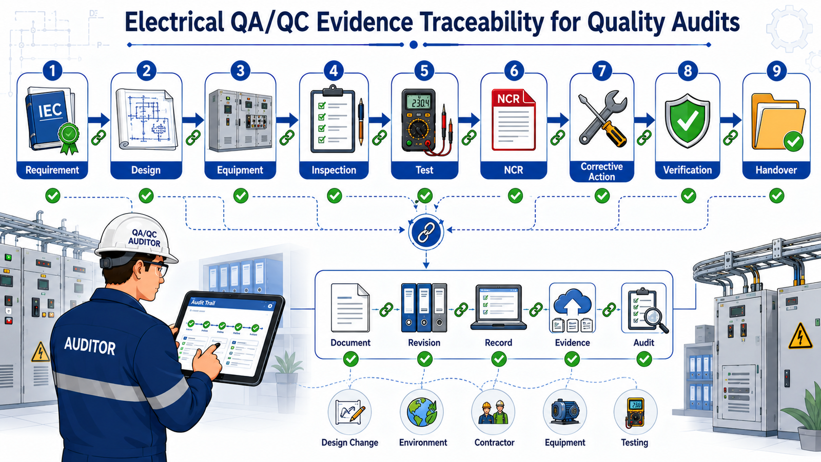
Why Audit Traceability Is Important
An electrical QA/QC audit is based on objective evidence. Auditors need to establish whether activities were performed according to defined requirements and whether the organisation can demonstrate effective control.
Clear traceability helps auditors determine:
- What requirement applied.
- Which document was current at the time.
- Which revision was used.
- What work was completed.
- Who performed or inspected the activity.
- What evidence was produced.
- What results were obtained.
- Whether results met acceptance criteria.
- What happened when requirements were not met.
- Whether corrective actions were implemented.
- Whether corrective actions were verified.
- Who approved the final status.
Without traceability, quality records may exist but fail to provide meaningful evidence.
For example, an electrical test certificate may show a satisfactory result but fail to identify the exact equipment tested. In such a case, the numerical result alone cannot reliably demonstrate that the correct equipment was tested.
Traceability in Environments with Interacting Factors
Interacting factors occur when several conditions influence one another and potentially affect quality outcomes.
Examples include:
- Design changes affecting material requirements.
- Material substitutions affecting installation procedures.
- Installation changes affecting testing.
- Environmental conditions affecting inspection.
- Electrical loading affecting thermographic findings.
- Equipment changes affecting commissioning procedures.
- Subcontractor activities affecting main contractor inspections.
- Client changes affecting approved drawings.
- Testing failures triggering corrective action.
- Corrective actions requiring re-inspection.
- Re-inspection results affecting handover status.
These interactions mean that a single document rarely provides the complete quality picture.
A strong documentation system therefore needs to connect related evidence rather than storing records independently.
Key Concepts of Audit Traceability
Document Traceability
Document traceability ensures that every controlled document can be identified and its history established.
It normally includes:
- Document number.
- Document title.
- Revision.
- Issue date.
- Approval status.
- Author.
- Reviewer.
- Approver.
- Distribution status.
- Superseded revision.
- Current revision.
This ensures that auditors can determine which information was officially applicable at a particular stage of the project.
Equipment Traceability
Equipment traceability links an installed electrical item to its technical and quality records.
Relevant information may include:
- Equipment tag.
- Manufacturer.
- Model.
- Serial number.
- Rating.
- Location.
- Procurement reference.
- Material approval.
- Installation record.
- Inspection record.
- Test certificate.
- Commissioning record.
- Maintenance information.
Equipment traceability is particularly important for switchgear, transformers, generators, motors, distribution boards, protection systems, control equipment, and other critical electrical assets.
Activity Traceability
Activity traceability establishes a connection between a specific work activity and its associated inspection and verification evidence.
Examples include:
- Cable installation.
- Cable termination.
- Containment installation.
- Panel installation.
- Earthing installation.
- Equipment installation.
- Functional testing.
- Protection testing.
- Commissioning.
Personnel Traceability
Quality records should identify appropriate personnel involved in inspection, testing, verification, review, or approval.
Depending on project requirements, this may include:
- Inspector.
- Tester.
- QA/QC Engineer.
- Electrical Engineer.
- NDE examiner where applicable.
- Contractor representative.
- Client representative.
- Consultant.
- Approver.
Personnel identification helps establish accountability and supports competency verification where required.
Time-Based Traceability
The timing of an activity can be important when interacting factors are involved.
Records may need to establish:
- Date.
- Time where relevant.
- Work shift.
- Inspection sequence.
- Test sequence.
- Equipment operating condition.
- Relevant environmental conditions.
For example, an electrical thermographic inspection conducted under low load may produce different results from an inspection conducted under normal operating load. Recording the operating condition helps an auditor understand the context of the finding.
Traceability Framework for Electrical QA/QC
A useful traceability framework can be visualised as:
Requirements → Design → Procurement → Installation → Inspection → Testing → Findings → Corrective Action → Verification → Approval → Handover
Each stage should contain controlled evidence and references to related records.
| Traceability Element | Definition | Typical Electrical QA/QC Evidence | Audit Purpose |
|---|---|---|---|
| Requirement | The technical, contractual, regulatory, or project condition that must be satisfied. | Specification, code, contract, approved requirement | Establishes the basis for conformity. |
| Design | Approved technical information defining the intended installation. | Drawings, calculations, schedules, diagrams | Demonstrates design intent. |
| Material/Equipment | Approved item incorporated into the installation. | Submittal, certificate, serial number, delivery inspection | Confirms material and equipment identity. |
| Installation | Physical implementation of the approved design. | Installation inspection, photographs, work records | Demonstrates execution. |
| Inspection | Verification that work meets defined requirements. | Inspection request, checklist, inspection report | Provides objective evidence of conformity. |
| Testing | Technical measurement or functional verification. | Test certificate, commissioning record | Demonstrates performance or condition. |
| Non-Conformance | Documented failure to satisfy a requirement. | NCR, observation report | Demonstrates controlled defect management. |
| Corrective Action | Action taken to address an identified deficiency. | Corrective action record, repair evidence | Demonstrates response to non-conformity. |
| Verification | Confirmation that corrective action or work satisfies requirements. | Re-inspection, re-test, approval | Demonstrates effectiveness. |
| Handover | Controlled transfer of completed quality evidence. | Quality dossier, as-built records, final certificates | Demonstrates final acceptance and record completeness. |
Establishing a Traceable Document Control System
The foundation of audit traceability is effective document control.
A document control system should establish:
- Unique document numbers.
- Revision control.
- Approval status.
- Controlled distribution.
- Access permissions.
- Document registers.
- Superseded document control.
- Record retention.
- Electronic audit trails.
- Backup arrangements.
The system should ensure that personnel at the point of work have access to the correct approved information.
Document Revision Control
Revision control is particularly important in environments with interacting factors because one change can affect multiple records.
For example, changing a distribution board design may affect:
- Single-line diagram.
- Panel schedule.
- Cable schedule.
- Protection settings.
- Load schedule.
- Material requirements.
- Installation arrangement.
- Inspection checklist.
- Testing procedure.
- Commissioning requirements.
- As-built drawing.
The documentation system should therefore identify related documents that require review when a design change is introduced.
Revision Control Process
A controlled process should include:
- Identify the proposed change.
- Record the change request.
- Assess technical implications.
- Identify affected documents.
- Revise technical information.
- Conduct technical review.
- Obtain required approval.
- Assign a new revision.
- Update the document register.
- Withdraw superseded information.
- Issue the approved revision.
- Communicate the change.
- Verify implementation.
- Update relevant quality records.
This prevents isolated document changes from creating inconsistencies elsewhere in the quality system.
Linking Inspection Records to Approved Requirements
Every inspection record should be traceable to the requirement against which the inspection was performed.
For example, a cable installation inspection may reference:
- Approved cable schedule.
- Approved electrical layout.
- Applicable installation specification.
- ITP activity.
- Inspection checklist.
- Acceptance criteria.
- Relevant method statement.
The inspector should be able to demonstrate why the installation was considered acceptable.
An auditor reviewing the inspection record should not have to guess which requirement was applied.
Linking Test Results to Specific Equipment
Test records must clearly establish the identity of the tested equipment.
A test record should, where applicable, include:
- Equipment identification.
- Circuit reference.
- Location.
- Test date.
- Test procedure.
- Test parameters.
- Test results.
- Instrument identification.
- Acceptance criteria.
- Tester identification.
- Review and approval.
For example, an insulation resistance test result without a cable identification cannot reliably demonstrate which cable was tested.
Similarly, a functional test showing “pass” without identifying the equipment, circuit, test condition, or procedure provides limited audit evidence.
Calibration Traceability
Measurement equipment should be controlled according to applicable project requirements and the organisation’s quality system.
Where calibration traceability is required, the documentation should establish the connection between:
Test Result → Instrument → Instrument ID → Calibration Status → Calibration Certificate
Relevant information may include:
- Instrument ID.
- Manufacturer.
- Model.
- Serial number.
- Calibration date.
- Calibration status.
- Calibration certificate.
- Measurement range.
- Relevant test record.
This allows an auditor to assess whether the measurement equipment was appropriately controlled at the time of testing.
Traceability of Non-Conformities
Non-conformance management is one of the most important areas of audit traceability.
An NCR should be traceable to:
- Original inspection.
- Exact location.
- Equipment or component.
- Applicable requirement.
- Finding.
- Supporting evidence.
- Responsible organisation.
- Proposed corrective action.
- Approval.
- Corrective work.
- Re-inspection.
- Re-testing where applicable.
- Final closure.
A closed NCR without supporting verification evidence is a weak quality record.
NCR Traceability Process
The process should include:
- Identify the non-conforming condition.
- Record objective evidence.
- Assign a unique NCR number.
- Identify the applicable requirement.
- Identify affected equipment or work.
- Assess impact.
- Define corrective action.
- Obtain required approval.
- Complete corrective action.
- Perform re-inspection.
- Perform re-testing where necessary.
- Record verification evidence.
- Obtain final approval.
- Close and retain the NCR.
This creates a complete history of the quality issue.
Traceability of Corrective Actions
Corrective action should not be documented as an isolated activity.
The record should clearly identify:
- Original problem.
- Root or contributing factors where required.
- Immediate correction.
- Corrective action.
- Responsible person.
- Completion date.
- Verification method.
- Verification result.
- Final status.
Where the issue has potentially wider implications, the documentation should identify whether similar equipment, locations, or installations were reviewed.
For example, if incorrect cable termination was identified on one distribution board, the QA/QC team may determine that similar boards should also be inspected. The resulting records should maintain a clear connection to the original finding and corrective action decision.
Managing Interacting Factors
Complex electrical projects may involve several interacting factors that influence the quality evidence.
Design and Construction Interaction
A design revision may be issued after construction has started.
The QA/QC system should determine:
- What areas were affected.
- What work had already been completed.
- Whether completed work requires re-inspection.
- Whether materials require replacement.
- Whether testing procedures have changed.
- Whether as-built information requires revision.
Procurement and Installation Interaction
A material substitution may be proposed because the originally specified equipment is unavailable.
The documentation should establish:
- Original approved item.
- Proposed substitute.
- Technical comparison.
- Approval decision.
- Revised documentation.
- Material delivery.
- Installation inspection.
- Testing requirements.
Testing and Operating Conditions
Electrical test results may depend on operating conditions.
The documentation may therefore need to capture:
- Equipment load.
- Ambient temperature.
- System configuration.
- Energised or de-energised condition.
- Test duration.
- Relevant environmental conditions.
This is particularly important for diagnostic and condition-based inspections.
Contractor and Subcontractor Interaction
Multiple organisations may contribute to one electrical system.
The traceability system should establish:
- Scope of each organisation.
- Inspection responsibility.
- Testing responsibility.
- Approval responsibilities.
- Interface points.
- Transfer of records.
This helps prevent gaps between subcontractor records and main contractor quality documentation.
Establishing a Quality Audit Evidence Matrix
A quality audit evidence matrix can provide a useful method for checking traceability before an audit.
The matrix may identify:
- Requirement.
- Evidence required.
- Evidence reference.
- Current status.
- Responsible person.
- Missing information.
- Corrective action.
For example:
Requirement → Approved Drawing → Installation Inspection → Test Certificate → NCR → Re-inspection → Final Approval
If one link is missing, the QA/QC team can investigate before the formal audit.
Benefits of an Evidence Matrix
It can:
- Identify documentation gaps.
- Improve audit readiness.
- Reduce search time.
- Clarify responsibilities.
- Highlight missing records.
- Support management review.
- Improve handover preparation.
Digital Traceability and Electronic Quality Management
Digital QA/QC platforms can significantly improve traceability when properly configured.
Useful capabilities include:
- Unique record identification.
- Automated revision history.
- Document relationships.
- Electronic signatures.
- Approval workflows.
- User permissions.
- Time-stamped records.
- Inspection workflows.
- NCR tracking.
- Photo attachment.
- Drawing association.
- Searchable records.
- Automated notifications.
- Audit trails.
For example, an electronic inspection record can be linked directly to an equipment tag and drawing. The inspector can record findings, attach photographs, raise an NCR, assign corrective action, and initiate re-inspection without losing the relationship between the records.
However, digital systems must be governed carefully.
Controls should address:
- User access.
- Data integrity.
- Record modification.
- Backup.
- Cybersecurity.
- Retention.
- Approval authority.
- Electronic signatures.
- System availability.
Maintaining Evidence Integrity
Audit evidence must remain reliable after it has been generated.
Evidence integrity means that records should remain:
- Accurate.
- Complete.
- Authentic.
- Legible.
- Traceable.
- Protected.
- Retrievable.
- Unaltered unless formally revised.
Important controls may include:
- Controlled user access.
- Read-only status for approved records.
- Revision history.
- Electronic audit trails.
- Secure storage.
- Backup.
- Controlled deletion.
- Document retention.
- Formal correction procedures.
If an error is identified in an approved record, the correction should be controlled rather than simply overwriting the original information.
Audit Trail Requirements
An audit trail should demonstrate the history of significant document or record activities.
Depending on the system, this may show:
- Who created the record.
- Who reviewed it.
- Who approved it.
- When it was issued.
- What revision was used.
- When it was changed.
- Who made the change.
- Why the change occurred.
- Which records were superseded.
An effective audit trail strengthens confidence in the reliability of the documentation system.
Procedure for Establishing Clear Audit Traceability
Step 1: Identify Audit Requirements
Determine:
- Applicable standards.
- Client requirements.
- Contract requirements.
- Regulatory requirements.
- Internal quality requirements.
Step 2: Identify Required Evidence
Establish what records are required to demonstrate conformity.
Step 3: Create Unique References
Assign unique identification to:
- Drawings.
- Inspections.
- Test records.
- NCRs.
- Corrective actions.
- Equipment.
- Quality dossiers.
Step 4: Establish Document Relationships
Connect:
- Requirements.
- Drawings.
- Materials.
- Equipment.
- Inspections.
- Tests.
- NCRs.
- Corrective actions.
- Verification.
- Handover.
Step 5: Control Revisions
Ensure the correct revision is used at the point of work.
Step 6: Verify Record Completeness
Check whether each record contains sufficient information.
Step 7: Review Interacting Factors
Assess whether:
- Design changes affect inspection.
- Material changes affect testing.
- Environmental conditions affect results.
- Contractor interfaces affect responsibilities.
- Corrective actions affect other equipment.
Step 8: Conduct Traceability Checks
Select sample records and trace them forwards and backwards.
Step 9: Correct Documentation Gaps
Where evidence is missing:
- Identify the gap.
- Investigate the reason.
- Determine whether reliable replacement evidence can be obtained.
- Perform additional verification where technically appropriate.
- Record the resolution.
Step 10: Conduct a Pre-Audit Review
Complete an internal traceability review before the formal audit.
Practical Example: Traceability of a Distribution Board
Consider a newly installed distribution board identified as DB-12.
The QA/QC documentation should allow an auditor to trace DB-12 through the complete quality process.
The traceability chain may include:
- Approved single-line diagram.
- Approved panel schedule.
- Approved equipment submittal.
- Manufacturer documentation.
- Delivery inspection.
- Equipment serial number.
- Installation inspection.
- Cable termination inspection.
- Earthing verification.
- Electrical test certificate.
- Functional test.
- Protection verification where applicable.
- NCR records if applicable.
- Corrective action.
- Re-inspection.
- Commissioning certificate.
- As-built drawing.
- Final handover record.
If an auditor identifies a test result for DB-12, the auditor should be able to determine exactly which board was tested, where it is installed, what requirements applied, which procedure was used, what instrument was used where relevant, who performed the test, and whether any related quality issues were resolved.
This is effective traceability.
Practical Example: Interacting Factors During Design Change
A project originally specifies a particular distribution board arrangement. During construction, the engineer approves a design revision that changes the number of outgoing circuits.
This change may affect:
- Panel schedule.
- Cable schedule.
- Protective devices.
- Load calculations.
- Panel fabrication.
- Cable termination.
- Testing.
- Commissioning.
- As-built documentation.
The QA/QC team should therefore establish a change traceability chain.
The record should show:
- Original approved design.
- Design change request.
- Technical review.
- Approved revised design.
- Affected equipment.
- Installation implementation.
- Revised inspection requirements.
- Revised testing.
- Commissioning verification.
- Updated as-built documentation.
If these relationships are not documented, an auditor may struggle to determine whether the final installation was properly controlled.
Case Study: Audit Failure Caused by Weak Traceability
Project Background
An industrial facility was undergoing a quality audit before final electrical handover. The project involved multiple contractors, several equipment suppliers, extensive cable systems, distribution equipment, control panels, and commissioning activities.
The project team had generated a large quantity of documentation. However, the records had not been sufficiently integrated.
Audit Findings
The auditor selected several electrical test certificates and discovered:
- Equipment identification was incomplete.
- Some certificates referenced obsolete drawing revisions.
- Several test instruments were not clearly identified.
- NCRs could not easily be linked to original inspections.
- Corrective actions lacked re-inspection evidence.
- Some photographs were not linked to inspection records.
- As-built drawings did not clearly correspond with several approved changes.
The problem was not a complete absence of documentation. The problem was weak traceability between documents.
Corrective Strategy
The QA/QC management team established an evidence-traceability programme.
The team:
- Created a master equipment register.
- Linked equipment tags to drawings.
- Reviewed test certificates.
- Verified document revisions.
- Cross-referenced NCRs.
- Reviewed corrective actions.
- Checked re-inspection evidence.
- Linked photographs to inspection records.
- Updated as-built information.
- Conducted sample traceability audits.
Outcome
The project developed a much stronger audit trail. Quality records could be retrieved more efficiently and linked to specific equipment and activities.
The case demonstrates an important principle: having a large quantity of documentation does not necessarily mean that the quality system is auditable. Auditability depends on the quality, accuracy, consistency, integrity, and traceability of the evidence.
Key Benefits of Clear Audit Traceability
Improved Audit Readiness
A traceable documentation system enables organisations to prepare more effectively for:
- Internal audits.
- Client audits.
- Certification audits.
- Regulatory inspections.
- Project quality reviews.
- Handover reviews.
Faster Evidence Retrieval
Auditors can locate relevant records quickly when documents have:
- Unique numbers.
- Equipment references.
- Revision information.
- Linked records.
- Controlled indexes.
Stronger Quality Assurance
Traceability helps demonstrate that quality processes are not isolated activities but part of a controlled system.
Improved Corrective Action
When the original finding, corrective action, and verification records are connected, quality teams can demonstrate that problems were properly addressed.
Better Root Cause Analysis
Historical traceability can help identify recurring problems and relationships between:
- Suppliers.
- Equipment.
- Work teams.
- Locations.
- Procedures.
- Design changes.
- Installation activities.
Improved Asset Management
Quality records can become valuable technical information after project completion.
They can support:
- Maintenance.
- Troubleshooting.
- Condition assessment.
- Future modifications.
- Reliability analysis.
- Asset replacement planning.
Reduced Contractual Risk
Clear records can provide objective evidence regarding:
- Scope.
- Responsibility.
- Compliance.
- Inspection status.
- Corrective actions.
- Acceptance.
Common Traceability Failures
Electrical QA/QC teams should avoid:
- Duplicate document numbers.
- Missing equipment identification.
- Uncontrolled revisions.
- Unlinked inspection records.
- Test certificates without equipment references.
- NCRs without original inspection references.
- Corrective actions without verification.
- Photographs without location information.
- Missing instrument identification where required.
- Incomplete approval records.
- Uncontrolled spreadsheets.
- Missing audit trails.
- Inconsistent terminology.
- Poor document indexing.
- Missing as-built updates.
- Uncontrolled record deletion.
- Inadequate backups.
- Failure to assess the effect of design changes.
These weaknesses can make a project appear poorly controlled even when the physical installation is technically satisfactory.
Responsibilities of the Electrical QA/QC Engineer
The Electrical QA/QC Engineer should ensure that traceability is incorporated into the quality system from the beginning rather than added shortly before an audit.
Key responsibilities include:
- Establishing traceability requirements.
- Reviewing applicable standards and specifications.
- Developing documentation procedures.
- Establishing inspection and test records.
- Defining equipment identification requirements.
- Reviewing document registers.
- Monitoring revision control.
- Checking test record traceability.
- Monitoring NCR documentation.
- Verifying corrective action records.
- Reviewing calibration evidence where applicable.
- Conducting internal traceability checks.
- Preparing audit evidence matrices.
- Supporting client and certification audits.
- Reviewing handover documentation.
- Identifying recurring documentation weaknesses.
- Implementing continual improvement.
The QA/QC Engineer should also encourage personnel to consider traceability while generating records rather than waiting until the audit stage. Every inspection record should be created with the understanding that someone may need to understand and verify that evidence months or years later.
Key Learning Points
By completing this part, learners should understand that:
- Traceability is essential for effective electrical QA/QC auditing.
- Quality evidence should be linked rather than maintained as isolated documents.
- Documents should have unique identification and controlled revisions.
- Equipment should be traceable through inspection, testing, commissioning, and handover.
- Inspection records should identify the applicable requirement.
- Test certificates should identify the equipment and relevant testing information.
- Calibration information should be traceable where required.
- NCRs should be connected to the original finding.
- Corrective actions should be linked to verification evidence.
- Design changes should be assessed for their effect on related quality records.
- Interacting factors must be considered when establishing audit evidence.
- Digital systems can improve traceability when properly controlled.
- Approved records should be protected against unauthorised alteration.
- Audit trails strengthen confidence in documentation integrity.
- Evidence matrices can identify missing documentation before audits.
- Traceable records support maintenance and asset management after handover.
- Auditability depends on the quality and relationships between records, not simply the quantity of documentation.
Conclusion
Ensuring clear traceability of documented evidence is one of the most important elements of an effective electrical QA/QC system. In complex projects, quality outcomes are influenced by many interacting factors, including design revisions, procurement decisions, installation activities, testing conditions, subcontractor interfaces, environmental conditions, equipment changes, corrective actions, and commissioning requirements. A professional documentation system must therefore demonstrate the relationship between these factors rather than treating each record as an isolated document.
Effective traceability creates a continuous evidence chain from requirement to design, procurement, installation, inspection, testing, finding, corrective action, verification, approval, and final handover. This allows auditors and other competent reviewers to establish not only what happened, but also why it happened, which requirement applied, who was responsible, what evidence was produced, and how conformity was ultimately demonstrated.
For the Electrical QA/QC Engineer, traceability should be designed into the quality system from the beginning of the project. Unique document identification, revision control, equipment identification, inspection references, test records, calibration information, NCR tracking, corrective action verification, digital audit trails, and controlled handover records all contribute to a reliable audit trail. When these elements are properly integrated, the organisation can demonstrate conformity with confidence and respond effectively to audits, client reviews, regulatory inspections, technical investigations, and future maintenance requirements.
Ultimately, clear audit traceability transforms quality documentation from a collection of administrative records into a structured body of objective technical evidence. It strengthens quality assurance, improves accountability, supports continual improvement, reduces contractual and technical uncertainty, and preserves valuable information throughout the complete electrical project and asset lifecycle.
4: Evaluate the Effectiveness of Current Documentation Practices in Capturing Comprehensive Inspection Data
Effective documentation is one of the foundations of a reliable electrical Quality Assurance and Quality Control (QA/QC) system. Inspection activities generate valuable technical information about electrical installations, equipment, materials, workmanship, testing, defects, non-conformities, corrective actions, and final acceptance. However, the existence of inspection records does not automatically mean that an organisation has an effective documentation system. The quality of the information captured, its completeness, accuracy, consistency, traceability, accessibility, and usefulness for decision-making must be evaluated.
Evaluating current documentation practices involves determining whether existing forms, inspection reports, checklists, digital systems, test certificates, photographs, NDE records, NCRs, commissioning documents, and other quality records actually capture the information needed to demonstrate conformity. A professional Electrical QA/QC Engineer must assess whether the documentation reflects the real condition of the installation and whether another competent person can understand what was inspected, where it was inspected, how it was inspected, which criteria were applied, what was found, and what action was taken.
The evaluation becomes particularly important on complex electrical projects where inspection data is generated by multiple inspectors, contractors, subcontractors, testing teams, engineers, consultants, and suppliers. Differences in terminology, reporting formats, document control practices, inspection methods, digital systems, and levels of technical competence can result in incomplete or inconsistent records. An effective evaluation therefore examines both the documentation itself and the processes used to generate, review, approve, store, retrieve, and use the information. The objective is to identify strengths, weaknesses, information gaps, duplication, unnecessary documentation, and opportunities for continual improvement.
Meaning of Evaluating Documentation Effectiveness
Evaluating documentation effectiveness means systematically assessing whether existing documentation practices are capable of capturing sufficient, accurate, relevant, traceable, and reliable inspection information.
The evaluation should consider whether the documentation:
Captures all critical inspection data.
Identifies the inspected equipment or component.
Records the inspection location.
Identifies the applicable requirements.
References the correct drawing revision.
Identifies the inspection or test method.
Records measurements correctly.
Captures relevant operating conditions.
Documents findings objectively.
Provides supporting evidence.
Identifies non-conformities.
Records corrective actions.
Provides re-inspection evidence.
Supports final acceptance.
Can be retrieved efficiently during an audit.
Supports future maintenance and engineering decisions.
The key question is not simply whether a form has been completed. The more important question is whether the completed record provides sufficient objective evidence to support a professional quality decision.
Why Documentation Effectiveness Matters in Electrical QA/QC
Electrical inspection documentation provides evidence that work has been verified against specified requirements. If the documentation is incomplete, the organisation may have difficulty demonstrating conformity even when the physical installation is satisfactory.
Weak documentation can result in:
Unclear inspection status.
Repeated inspections.
Delayed handover.
Difficulty investigating defects.
Poor audit performance.
Increased contractual disputes.
Lost technical information.
Ineffective corrective actions.
Weak maintenance records.
Poor trend analysis.
Difficulty identifying recurring quality problems.
Effective documentation, by contrast, can provide:
Clear quality evidence.
Strong traceability.
Faster audits.
Better corrective action.
Improved project control.
More reliable handover.
Improved asset information.
Better management decisions.
Therefore, evaluating documentation practices should be treated as a quality improvement activity rather than merely an administrative review.
Key Concepts for Evaluating Documentation Practices
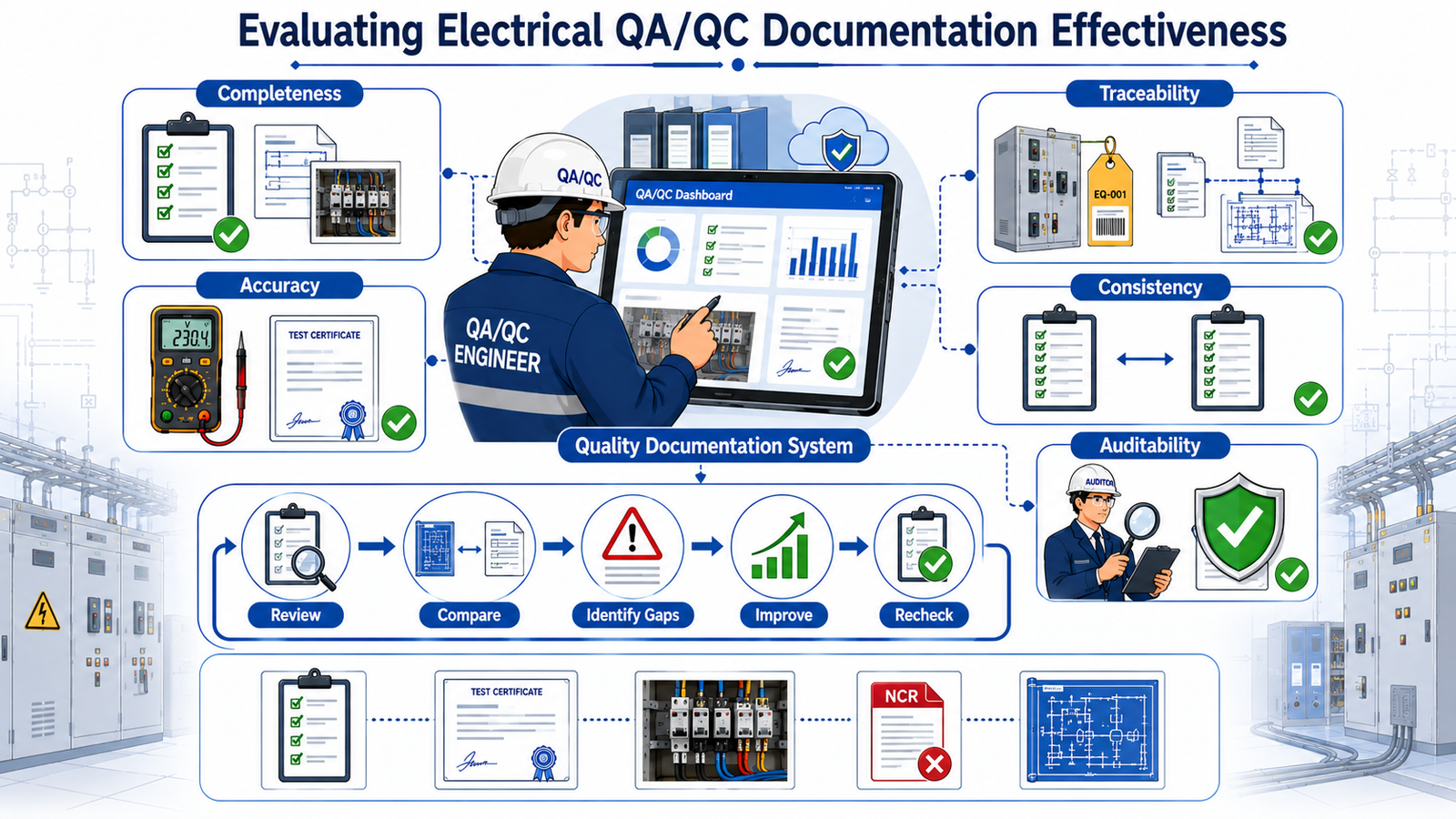
Completeness
Completeness means that the inspection record contains all information necessary to understand and verify the inspection.
A complete electrical inspection record may include:
Project identification.
Inspection reference.
Date.
Location.
Equipment identification.
Circuit or system identification.
Drawing reference.
Drawing revision.
Specification reference.
Inspection procedure.
Inspection method.
Acceptance criteria.
Inspection findings.
Measurements.
Test results.
Supporting photographs.
Inspector identification.
Inspection status.
Corrective action requirements.
Verification status.
Approval information.
A record may be formally completed while still being incomplete. For example, a checklist with every box ticked but no equipment identification provides limited traceability.
Accuracy
Accuracy means that the information recorded reflects the actual inspection activity and results.
Accuracy includes:
Correct equipment identification.
Correct measurements.
Correct units.
Correct dates.
Correct drawing revision.
Correct test method.
Correct acceptance criteria.
Correct status.
Correct personnel information.
Transcription errors should be minimised through controlled processes and appropriate review.
Relevance
Not every piece of information has equal value. Documentation should capture information relevant to the inspection objective.
For example, a thermographic inspection should focus on information necessary to understand thermal conditions, such as:
Equipment identity.
Circuit.
Load condition.
Measured temperature.
Reference temperature.
Thermal image.
Inspection conditions.
Evaluation criteria.
Unnecessary information can make records more difficult to review.
Consistency
Different inspectors should produce records using consistent:
Terminology.
Units.
Status classifications.
Document references.
Finding descriptions.
Acceptance criteria.
Inspection categories.
Consistency improves comparison and trend analysis.
Traceability
Inspection records should be linked to:
Equipment.
Location.
Drawing.
Specification.
Inspection request.
Test record.
NCR.
Corrective action.
Re-inspection.
Final acceptance.
Without traceability, the value of inspection data is significantly reduced.
Accessibility
Documentation should be available to authorised personnel when required.
An effective system should allow users to locate:
Current drawings.
Inspection records.
Test certificates.
NCRs.
Corrective actions.
Calibration records.
Handover information.
Digital systems can improve accessibility, but only when documents are properly indexed and controlled.
Reliability
Inspection data should be generated and maintained through controlled processes. Records should be protected from:
Unauthorised modification.
Accidental deletion.
Loss.
Uncontrolled duplication.
Incorrect revision.
Data corruption.
Documentation Effectiveness Evaluation Framework
A systematic evaluation can use several criteria.
| Evaluation Area | Definition | Questions for QA/QC Evaluation | Evidence to Review |
|---|---|---|---|
| Completeness | Extent to which required inspection information is captured. | Are all critical fields completed? | Inspection forms, checklists, test records |
| Accuracy | Degree to which recorded information reflects actual conditions. | Are measurements, IDs and references correct? | Test records, drawings, field verification |
| Traceability | Ability to link records to equipment, requirements and actions. | Can findings be traced to specific items? | Equipment registers, NCRs, inspection records |
| Consistency | Degree to which records follow standard practices. | Are terminology and formats consistent? | Sample inspection reports |
| Relevance | Extent to which captured information supports the inspection objective. | Are useful data captured without unnecessary duplication? | Forms and inspection procedures |
| Timeliness | Degree to which records are completed at the appropriate stage. | Are records generated promptly? | Inspection dates, submission records |
| Accessibility | Ease of retrieving authorised information. | Can records be found quickly? | Document management system |
| Integrity | Protection of records from unauthorised changes or loss. | Is the record history controlled? | Audit trails, permissions, revision history |
| Auditability | Ability to demonstrate conformity through objective evidence. | Can an auditor reconstruct the inspection history? | Complete quality dossier |
| Usability | Ease with which personnel can understand and use the records. | Are forms clear and technically practical? | User feedback, completed forms |
Reviewing Existing Inspection Forms and Checklists
The first practical step in evaluating documentation practices is to review the existing forms and checklists.
The QA/QC Engineer should examine whether each form captures the information required for the relevant activity.
For example, a cable installation checklist should potentially address:
Cable identification.
Cable type.
Cable size.
Route.
Support arrangement.
Bend radius where applicable.
Separation requirements.
Identification.
Protection from damage.
Termination preparation.
Gland installation.
Earthing or bonding requirements where applicable.
Inspection status.
Supporting evidence.
A form that only provides “Accepted / Rejected” may be insufficient for a complex installation.
Questions to Ask During Form Evaluation
Does the form identify the exact equipment?
Does it identify the inspection location?
Does it reference the approved drawing?
Does it identify the applicable specification?
Are acceptance criteria clear?
Can measurements be recorded?
Are units specified?
Can abnormal findings be described?
Is there space for photographs?
Can NCR references be recorded?
Is re-inspection captured?
Are inspector and reviewer details included?
Is the revision of the form controlled?
Evaluating Inspection Data Quality
The next stage is to review actual completed records rather than only blank forms.
Sampling should include records from:
Different inspectors.
Different contractors.
Different project areas.
Different electrical systems.
Different inspection stages.
Different dates.
Different types of findings.
The purpose is to identify whether the documentation system works effectively in practice.
The evaluator should look for:
Missing information.
Inconsistent terminology.
Incorrect references.
Unclear findings.
Missing measurements.
Missing units.
Incomplete signatures or approvals.
Unclear equipment identification.
Incorrect drawing revisions.
Missing photographs.
Unclosed findings.
Weak corrective action evidence.
Evaluating Inspection Data Against Acceptance Criteria
Inspection data has limited value if it cannot be compared with defined acceptance requirements.
The evaluator should determine whether records clearly identify:
Applicable specification.
Drawing requirement.
Code requirement.
Manufacturer requirement.
Test procedure.
Acceptance limit.
Inspection criteria.
For example, a test record stating “Pass” provides less useful evidence than a record showing:
Parameter tested.
Actual result.
Unit.
Acceptance limit.
Applicable procedure.
Equipment identification.
Test condition.
Final status.
The objective is to establish how the conclusion was reached.
Evaluating Measurement Data
Electrical inspection frequently involves measurements.
Examples include:
Voltage.
Current.
Resistance.
Insulation resistance.
Earth resistance.
Continuity.
Temperature.
Power quality parameters.
Protection test values.
Measurement documentation should be evaluated for:
Correct units.
Appropriate decimal precision.
Instrument identification where required.
Test conditions.
Measurement location.
Acceptance criteria.
Result interpretation.
A measurement without context may be technically correct but operationally meaningless.
For example, recording “0.8” without identifying whether it represents resistance, current, voltage, or another parameter is inadequate.
Evaluating Photographic Evidence
Photographs can strengthen inspection records, but their effectiveness depends on traceability and relevance.
The evaluator should determine whether photographs:
Clearly show the relevant condition.
Identify the location.
Relate to the inspection record.
Show sufficient context.
Have appropriate image references.
Are stored securely.
Can be retrieved later.
A photograph without an equipment reference may be difficult to use during an audit.
For complex findings, both overview and close-up images can be useful.
Evaluating Digital Documentation Systems
Many electrical QA/QC teams use electronic platforms to manage inspection data.
An evaluation should consider:
Ease of data entry.
Mobile accessibility.
Document search.
Revision control.
User permissions.
Approval workflows.
Audit trails.
Photo attachments.
Equipment tagging.
NCR integration.
Reporting capability.
Backup.
Data security.
Digital systems should be evaluated based on whether they improve quality evidence rather than simply whether they reduce paper.
Advantages of Digital Documentation
Faster data capture.
Improved accessibility.
Automatic timestamps.
Reduced transcription.
Easier photo integration.
Improved document searching.
Better status tracking.
Automated notifications.
Improved audit trails.
Faster reporting.
Potential Digital Weaknesses
Poorly designed forms.
Excessive mandatory fields.
Weak user permissions.
Incorrect data entry.
Uncontrolled exports.
Poor connectivity.
Duplicate records.
Inadequate backups.
Weak integration between systems.
Technology should support the quality process rather than replace professional judgement.
Evaluating Documentation Across Interacting Factors
Electrical quality data can be affected by several interacting factors. Documentation should provide enough information to understand these relationships.
Design Changes
The evaluator should determine whether inspection records identify the correct drawing revision.
A design change may affect:
Equipment.
Cable routes.
Protection settings.
Load calculations.
Installation requirements.
Testing.
Commissioning.
The documentation system should make these relationships visible.
Environmental Conditions
Some inspections are affected by:
Temperature.
Humidity.
Dust.
Moisture.
Weather.
Accessibility.
Where relevant, these conditions should be captured.
Electrical Loading
Condition-based inspections such as thermography can depend on operating load.
The evaluator should determine whether records capture:
Equipment load.
Circuit status.
Operating condition.
Ambient temperature.
Inspection time.
Without this information, comparison between inspection results may be unreliable.
Contractor Interfaces
Where several organisations work on the same electrical system, documentation should establish responsibilities.
The evaluation should consider:
Who inspected.
Who tested.
Who reviewed.
Who approved.
Who corrected.
Who verified.
Material Changes
Substitution of electrical equipment or materials should be traceable.
The evaluator should verify that documentation identifies:
Original approved material.
Proposed alternative.
Technical approval.
Revised documentation.
Installation inspection.
Testing requirements.
Evaluating Non-Conformance Documentation
NCR records should be evaluated for completeness and effectiveness.
A strong NCR should identify:
NCR number.
Date.
Location.
Equipment.
Finding.
Requirement.
Supporting evidence.
Responsible party.
Corrective action.
Target date.
Completion date.
Re-inspection.
Verification.
Closure approval.
The evaluator should determine whether NCRs provide a complete story from identification to closure.
Common NCR Weaknesses
Vague findings.
No requirement reference.
No equipment identification.
Weak corrective action.
Missing verification.
Unclear closure status.
No evidence of re-inspection.
Duplicate NCRs.
Long-open NCRs without escalation.
Evaluating Corrective Action Records
Corrective actions should address the identified problem and, where required, the underlying cause.
The evaluator should determine whether the records demonstrate:
What was corrected.
Who corrected it.
When it was corrected.
What evidence supports completion.
Whether re-inspection was performed.
Whether testing was repeated.
Whether the action was effective.
If recurring defects continue to appear, the organisation should investigate whether current corrective action processes are sufficiently effective.
Evaluating Inspection Documentation Through Audits
Audits provide a practical method for evaluating documentation effectiveness.
The auditor or QA/QC Engineer can select a sample and trace it through the quality system.
For example:
Approved Drawing → Material Approval → Installation Inspection → Test Certificate → NCR → Corrective Action → Re-Inspection → Commissioning → Handover
If the chain is complete, documentation is likely to provide strong traceability.
If links are missing, the evaluator should identify why.
Process for Evaluating Current Documentation Practices
Step 1: Define Evaluation Objectives
Establish what the evaluation is intended to determine.
Objectives may include:
Completeness.
Accuracy.
Traceability.
Compliance.
Audit readiness.
Usability.
Efficiency.
Step 2: Identify Applicable Requirements
Review:
Project specifications.
Quality plans.
ITPs.
Inspection procedures.
Applicable standards.
Client requirements.
Contract requirements.
Step 3: Map the Existing Documentation Process
Identify how information moves from:
Requirement → Inspection → Record → Review → Corrective Action → Approval → Handover
Step 4: Review Documentation Templates
Assess:
Forms.
Checklists.
Test certificates.
NCRs.
Inspection reports.
Digital forms.
Step 5: Sample Completed Records
Select representative records across different:
Inspectors.
Locations.
Systems.
Contractors.
Inspection types.
Step 6: Assess Data Quality
Check:
Completeness.
Accuracy.
Consistency.
Relevance.
Traceability.
Step 7: Identify Documentation Gaps
Record:
Missing fields.
Missing references.
Duplicate information.
Unclear responsibilities.
Weak approval controls.
Step 8: Evaluate Digital Systems
Review:
Searchability.
Audit trails.
Access control.
Data integrity.
Integration.
Step 9: Obtain User Feedback
Consult:
Inspectors.
QA/QC Engineers.
Electrical Engineers.
Supervisors.
Contractors.
Document controllers.
Step 10: Analyse Findings
Classify weaknesses according to their impact.
For example:
Critical.
Major.
Moderate.
Minor.
Improvement opportunity.
Step 11: Develop Improvement Actions
Possible actions include:
Revising forms.
Improving checklists.
Adding mandatory fields.
Standardising terminology.
Improving training.
Integrating digital systems.
Strengthening review processes.
Step 12: Verify Improvement
After changes are implemented, repeat sampling to determine whether documentation quality has improved.
Practical Example: Evaluating Cable Installation Documentation
A QA/QC Engineer evaluates the current cable installation inspection system on a large commercial project.
The existing checklist contains:
Cable reference.
Installation status.
Visual inspection.
Inspector signature.
The evaluator reviews 50 completed records and discovers that:
Several records do not identify the drawing revision.
Some cable routes are not clearly identified.
No field is available for cable size.
Photographs are not consistently linked.
Corrective action references are missing.
Acceptance criteria are not clearly stated.
Although the inspection process is being performed, the documentation does not capture sufficient information for comprehensive audit evidence.
The QA/QC Engineer revises the checklist to include:
Cable identification.
Cable size.
Cable type.
Route reference.
Drawing revision.
Installation condition.
Support arrangement.
Identification.
Termination status.
Applicable acceptance criteria.
Photograph reference.
NCR reference.
Inspector.
Reviewer.
Final status.
A second sample is then conducted after implementation.
The results demonstrate improved completeness and traceability.
Practical Example: Evaluating Thermographic Inspection Records
A QA/QC team reviews thermographic inspection records for electrical distribution equipment.
The existing records contain thermal images and equipment names but do not consistently capture load conditions.
The evaluator identifies a significant limitation. Thermal readings can be influenced by operating conditions, so comparisons between different inspection dates may be unreliable if the load conditions are unknown.
The documentation is therefore improved to capture:
Equipment identification.
Circuit.
Inspection date.
Load condition.
Ambient temperature where relevant.
Measured temperature.
Reference temperature.
Thermal image.
Instrument identification.
Evaluation criteria.
Finding.
Recommended action.
Follow-up status.
This demonstrates how documentation effectiveness depends not only on the quantity of data but also on whether the captured information provides sufficient context for technical interpretation.
Case Study: Evaluation of an Electrical QA/QC Documentation System
Project Background
A major industrial facility was approaching commissioning. The electrical installation included switchgear, transformers, generators, motor control centres, distribution boards, power cables, control systems, lighting, emergency systems, and earthing infrastructure.
The project had generated thousands of inspection and testing records.
Management believed that the documentation system was effective because the number of completed records was high.
Evaluation
The Electrical QA/QC Engineer conducted a systematic evaluation rather than relying on record quantity.
A sample of inspection records was reviewed against:
Project specifications.
Approved drawings.
ITP requirements.
Test procedures.
Equipment identification.
NCR records.
Handover requirements.
Findings
The evaluation identified:
Inconsistent inspection terminology.
Missing drawing revisions.
Incomplete equipment identification.
Test certificates without consistent instrument references.
Photographs without reliable traceability.
Some NCRs without clear re-inspection evidence.
Duplicate inspection records.
Excessive information on some forms but insufficient critical information on others.
Delays in record submission.
Weak links between inspection and commissioning documentation.
Root Causes
The problems were attributed to:
Multiple subcontractors using different forms.
Limited training.
Poor document control.
Lack of standardised terminology.
Digital systems not fully integrated.
Excessive reliance on manual data entry.
Inadequate periodic review of documentation effectiveness.
Improvement Programme
The QA/QC team implemented:
Standardised electrical inspection templates.
Controlled terminology.
Mandatory equipment identification.
Drawing revision fields.
Integrated NCR references.
Improved photograph indexing.
Updated digital workflows.
Inspector training.
Monthly documentation audits.
Pre-handover traceability reviews.
Outcome
The improved system produced more consistent and auditable inspection records. The organisation also reduced the time required to retrieve evidence during internal reviews and client audits.
The case demonstrates that documentation effectiveness should be evaluated based on the quality and usefulness of information rather than the number of records produced.
Key Benefits of Evaluating Documentation Practices
Improved Inspection Quality
Evaluating documentation helps identify whether inspectors have the tools and information required to record findings properly.
Improved Audit Readiness
Regular evaluation ensures that missing records and weak traceability are identified before formal audits.
Better Data Quality
The process can identify:
Missing information.
Incorrect values.
Inconsistent terminology.
Poor references.
Duplicate records.
Improved Decision-Making
High-quality inspection data provides better information for:
Engineering decisions.
Maintenance planning.
Corrective actions.
Risk management.
Commissioning.
Asset management.
Improved Handover
A complete documentation system supports reliable handover of:
Test certificates.
Inspection records.
As-built information.
Equipment records.
Commissioning evidence.
Reduced Administrative Waste
Evaluation can identify unnecessary or duplicated documentation and simplify forms without reducing quality evidence.
Improved Continual Improvement
Trends in documentation weaknesses can reveal opportunities to improve:
Training.
Procedures.
Inspection methods.
Digital systems.
Contractor management.
Quality planning.
Common Weaknesses in Current Documentation Practices
Organisations should be alert to:
Overly complicated forms.
Forms that are too simple.
Missing acceptance criteria.
Excessive tick-box reporting.
Lack of space for technical findings.
Poor equipment identification.
Missing drawing revisions.
Unclear measurement units.
Missing test conditions.
Unlinked photographs.
Weak NCR integration.
Poor digital workflows.
Inconsistent terminology.
Delayed record submission.
Uncontrolled spreadsheets.
Duplicate records.
Incomplete approval information.
A particularly important warning sign is when inspectors regularly add handwritten notes or separate documents because the official form does not provide sufficient space or fields. This indicates that the documentation system may not adequately reflect actual inspection requirements.
Responsibilities of the Electrical QA/QC Engineer
The Electrical QA/QC Engineer should take an active role in evaluating documentation effectiveness.
Responsibilities may include:
Reviewing existing inspection forms.
Comparing records against project requirements.
Sampling completed documentation.
Identifying information gaps.
Reviewing inspection data quality.
Checking traceability.
Evaluating NCR records.
Reviewing test documentation.
Assessing digital systems.
Consulting inspectors and engineers.
Monitoring recurring documentation problems.
Developing improvement actions.
Training personnel.
Conducting follow-up reviews.
Reporting findings to management.
The engineer should also recognise that documentation effectiveness is not a one-time assessment. Requirements, technologies, project complexity, equipment types, and client expectations can change. Documentation systems should therefore be periodically reviewed and improved.
Key Performance Indicators for Documentation Effectiveness
Organisations can use measurable indicators to monitor documentation quality.
Potential indicators include:
Percentage of inspection records completed correctly.
Percentage of records submitted on time.
Percentage of records requiring correction.
Percentage of records with complete equipment traceability.
Percentage of NCRs closed with verified evidence.
Average document retrieval time.
Number of duplicate records.
Number of audit findings related to documentation.
Number of missing inspection records.
Percentage of current documents available at points of use.
Percentage of test records with complete equipment identification.
Percentage of handover records accepted without rework.
These indicators can help management identify whether documentation performance is improving.
Key Learning Points
By completing this part, learners should understand that:
The existence of documentation does not automatically demonstrate documentation effectiveness.
Inspection records must capture sufficient information to support technical decisions.
Documentation should be complete, accurate, relevant, consistent, traceable, accessible, and reliable.
Inspection forms should be evaluated against actual project requirements.
Completed records should be sampled to determine whether procedures work in practice.
Acceptance criteria should be clearly connected to inspection findings.
Measurements should include appropriate units and relevant conditions.
Photographic evidence should be traceable to specific inspection findings.
Digital systems should be evaluated for functionality, integrity, accessibility, and auditability.
Interacting factors such as design changes, environmental conditions, loading, and contractor interfaces should be considered.
NCR and corrective action documentation should be evaluated from identification through closure.
Documentation gaps should be identified before formal audits.
Documentation effectiveness can be measured using meaningful performance indicators.
Forms should capture critical information without creating unnecessary administrative burden.
Continuous evaluation supports continual improvement of electrical QA/QC systems.
High-quality inspection data supports audits, commissioning, handover, maintenance, and asset management.
Conclusion
Evaluating the effectiveness of current documentation practices is an essential component of professional electrical QA/QC management. A documentation system should not be judged by the number of completed forms or the volume of information stored. Its effectiveness depends on whether the records provide accurate, complete, relevant, consistent, traceable, and objective evidence of inspection and testing activities.
A systematic evaluation should examine inspection forms, checklists, test certificates, NDE records, photographs, NCRs, corrective action records, digital platforms, document registers, and handover documentation. The evaluator should compare these records with applicable project requirements and determine whether an independent competent person could understand what was inspected, where it was inspected, how it was inspected, which criteria were applied, what was found, and how the final decision was reached.
The evaluation should also consider interacting factors such as design revisions, material changes, operating conditions, environmental influences, contractor interfaces, testing limitations, and commissioning requirements. These factors can significantly influence the interpretation and usefulness of inspection data. Comprehensive documentation should therefore capture sufficient context to support reliable technical evaluation.
For the Electrical QA/QC Engineer, evaluating documentation practices is an ongoing quality improvement responsibility. Regular sampling, audits, performance indicators, user feedback, and review of recurring documentation problems can reveal weaknesses before they develop into significant audit, contractual, or technical issues. Improvements may involve redesigning forms, standardising terminology, strengthening document control, improving digital workflows, training personnel, or eliminating unnecessary duplication.
Ultimately, effective documentation should make quality information easier to understand, verify, audit, retrieve, and use. When inspection data is systematically evaluated and documentation practices are continually improved, the resulting quality records become a reliable source of technical evidence. This strengthens electrical QA/QC performance, supports international project requirements, improves audit readiness, facilitates commissioning and handover, assists future maintenance and asset management, and contributes to continual improvement throughout the complete electrical project lifecycle.