
Lesson 3: Predict potential failures and implement measures to prevent mechanical defects.
Mechanical component failure can lead to production interruptions, equipment damage, costly repairs, quality defects, and significant operational risks. Lesson 2: Predict potential failures and implement measures to prevent mechanical defects focuses on the systematic identification, assessment, and prevention of failure mechanisms across mechanical components and manufacturing systems. It examines how engineering teams can use inspection findings, operating data, material behaviour, maintenance records, vibration trends, stress conditions, dimensional measurements, and historical defect information to identify early warning signs before they develop into serious mechanical failures. This approach supports proactive mechanical QA/QC by moving beyond the detection of defects after they occur towards evidence-based prediction and prevention.
Predictive mechanical quality control requires an understanding of how defects develop and how different operating conditions influence component reliability. Potential problems may arise from excessive stress, fatigue, wear, corrosion, material degradation, dimensional inaccuracies, manufacturing defects, poor alignment, inadequate process control, thermal effects, vibration, or unsuitable operating conditions. By analysing these factors systematically, engineering and QA/QC professionals can determine where failure is most likely to occur, assess the consequences, and establish preventive measures proportionate to the level of risk. Techniques such as trend analysis, inspection planning, condition monitoring, root-cause investigation, preventive maintenance, process controls, material verification, and targeted corrective actions can provide valuable evidence for preventing recurring mechanical defects.
The lesson also develops a data-driven approach to mechanical reliability and defect prevention. Effective failure prediction should connect technical evidence with practical engineering decisions, ensuring that identified risks lead to measurable preventive action. This includes prioritising critical components, defining appropriate inspection intervals, monitoring degradation indicators, improving manufacturing parameters, controlling process variation, and verifying that corrective measures have reduced the likelihood of recurrence. Through this approach, mechanical QA/QC becomes an active reliability function that supports safer equipment operation, improved component performance, reduced downtime, better production efficiency, and sustained product quality. The principles covered are relevant to mechanical manufacturing, fabrication, maintenance, industrial production, rotating equipment, pressure systems, piping, valves, and other engineering environments where preventing mechanical defects is essential to operational reliability.
1. Apply Predictive Frameworks, Such as Failure Mode and Effects Analysis (FMEA), to Identify Hidden Weak Points in Complex Mechanical Assemblies
Failure prevention in mechanical engineering requires more than identifying defects after they have appeared. A robust QA/QC approach seeks to anticipate how a component, assembly, manufacturing process, or operating condition could fail and then establish controls before failure occurs. Failure Mode and Effects Analysis (FMEA) is one of the most useful structured techniques for achieving this objective because it provides a systematic method for examining how individual failure modes can affect component performance, system functionality, quality, reliability, and operational safety.
In complex mechanical assemblies, failure rarely results from a single obvious defect. A rotating assembly, valve system, gearbox, pump, pressure-containing arrangement, coupling, hydraulic mechanism, or fabricated structure may contain numerous interacting components. A relatively minor issue such as misalignment, inadequate lubrication, incorrect material condition, excessive dimensional variation, fastener loosening, surface damage, or abnormal vibration can initiate a chain of events that eventually produces a major failure. FMEA helps engineering and QA/QC professionals examine these relationships systematically rather than relying solely on experience or reactive inspection.
The application of FMEA is particularly valuable when mechanical systems contain multiple interfaces, critical load paths, moving components, pressure boundaries, manufacturing processes, or operating conditions that may change over time. By identifying potential failure modes, their causes and effects, existing controls, and relative priorities, the engineering team can focus preventive resources on the weaknesses most likely to compromise reliability or quality.
Understanding Failure Mode and Effects Analysis
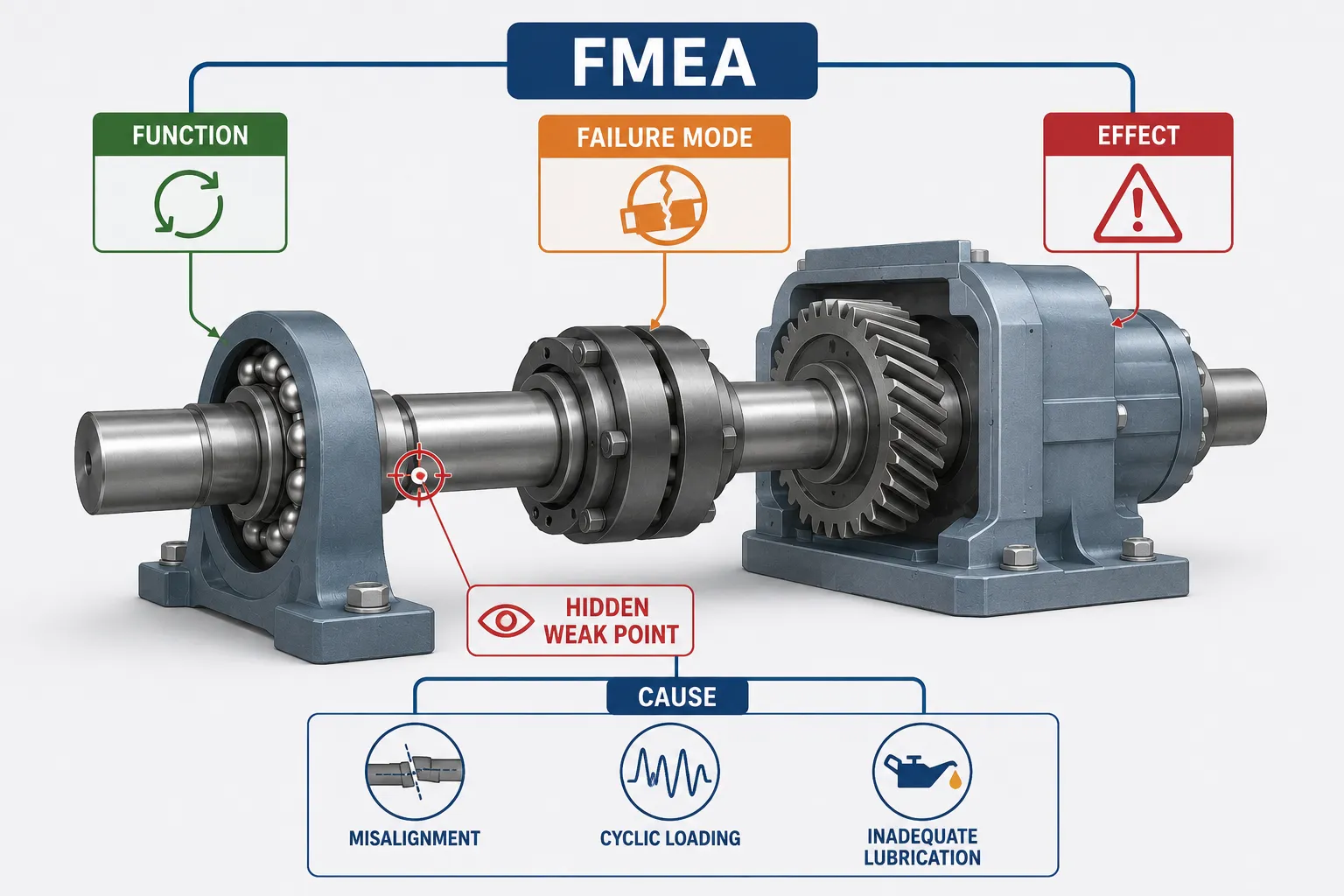
Failure Mode and Effects Analysis is a structured, proactive risk-analysis method used to identify potential ways in which a component, process, or system could fail and to evaluate the consequences of those failures.
The central questions of an FMEA are:
- What is the component or process intended to do?
- How could it fail to perform that function?
- What could cause the failure?
- What would happen if the failure occurred?
- How likely is the failure?
- How effectively could existing controls detect or prevent it?
- Which risks require priority action?
- What additional controls could reduce the risk?
FMEA therefore moves QA/QC thinking from:
“What defect has occurred?”
towards:
“What could fail, why could it fail, and what can be done before it happens?”
This predictive perspective supports preventive quality management and mechanical reliability improvement.
Purpose of FMEA in Mechanical QA/QC
FMEA can be used throughout the lifecycle of mechanical equipment, including:
- Design development.
- Material selection.
- Manufacturing.
- Machining.
- Welding.
- Assembly.
- Installation.
- Commissioning.
- Operation.
- Inspection.
- Maintenance.
- Modification.
Its main purpose is to identify weaknesses before they develop into unacceptable failures.
FMEA can help identify:
- Hidden mechanical weaknesses.
- Critical failure modes.
- Manufacturing-related defects.
- Material-related risks.
- Assembly errors.
- Design weaknesses.
- Inspection gaps.
- Maintenance-related failures.
- Operating-condition risks.
- Interface problems between components.
- Recurring quality problems.
Key FMEA Concepts and Definitions
| Key concept | Definition | Mechanical QA/QC application |
|---|---|---|
| Function | Intended purpose of a component or process | Defines what the component must achieve |
| Failure mode | Specific way a function could fail | Shaft fracture, leakage, excessive wear |
| Failure effect | Consequence produced by the failure | Loss of rotation, leakage, vibration |
| Failure cause | Underlying reason for the failure | Misalignment, fatigue, corrosion |
| Severity | Relative significance of the failure effect | Helps prioritise serious consequences |
| Occurrence | Relative likelihood of the failure cause | Indicates frequency or probability concern |
| Detection | Ability of existing controls to identify the failure | Indicates how easily a developing failure may be detected |
| Risk priority | Relative ranking used to focus improvement | Helps determine where action should begin |
| Preventive control | Measure intended to reduce failure likelihood | Design improvement, process control |
| Detection control | Measure intended to identify a problem | Inspection, testing, monitoring |
| Recommended action | Proposed improvement to reduce risk | Redesign, inspection or process change |
| Residual risk | Remaining risk after controls are applied | Supports verification of improvement |
Understanding Failure Modes
A failure mode describes how a component or system could fail to fulfil its intended function.
Examples in mechanical engineering include:
- Shaft fracture.
- Shaft bending.
- Excessive wear.
- Bearing seizure.
- Gear tooth breakage.
- Gear tooth wear.
- Coupling misalignment.
- Valve leakage.
- Pipe leakage.
- Seal failure.
- Fastener loosening.
- Weld cracking.
- Material deformation.
- Corrosion.
- Excessive vibration.
- Dimensional distortion.
- Thermal degradation.
- Loss of lubrication.
The failure mode should be described precisely. For example, “pump failure” is too broad for an effective FMEA. More useful descriptions might include “bearing seizure”, “mechanical seal leakage”, or “impeller imbalance”.
Identifying Component Functions
An effective FMEA begins by understanding what the component or assembly is supposed to do.
For example, a mechanical shaft may have functions such as:
- Transmit torque.
- Maintain rotational alignment.
- Support rotating elements.
- Operate within a defined speed range.
- Withstand expected bending loads.
A valve may need to:
- Control fluid flow.
- Maintain pressure containment.
- Open reliably.
- Close reliably.
- Maintain sealing performance.
A gearbox may need to:
- Transmit power.
- Provide a specified speed reduction.
- Maintain gear alignment.
- Operate within an established temperature range.
- Maintain lubrication conditions.
Clearly defining the function makes it easier to identify meaningful failure modes.
Identifying Hidden Weak Points
Complex assemblies often contain weaknesses that are not immediately visible during routine inspection.
Hidden weak points can occur at:
- Component interfaces.
- Keyways.
- Weld toes.
- Bolted connections.
- Bearings.
- Seals.
- Gaskets.
- Shaft shoulders.
- Gear teeth.
- Coupling connections.
- Material transitions.
- Heat-affected zones.
- Areas of high stress concentration.
- Locations with poor lubrication.
- Areas exposed to corrosive environments.
FMEA encourages the engineering team to examine the entire functional chain rather than focusing only on individual components.
Failure Causes in Mechanical Assemblies
Once a failure mode has been identified, the team investigates possible causes.
Potential causes include:
Design-related causes
- Insufficient component dimensions.
- Inadequate stress margin.
- Poor geometry.
- Excessive stress concentration.
- Incorrect material selection.
- Inadequate tolerance specification.
Manufacturing causes
- Incorrect machining parameters.
- Dimensional variation.
- Poor surface finish.
- Heat-treatment error.
- Welding defects.
- Improper assembly.
- Contamination.
- Material substitution.
Installation causes
- Misalignment.
- Incorrect tightening.
- Improper support.
- Incorrect orientation.
- Inadequate lubrication.
Operational causes
- Excessive loading.
- Pressure surges.
- Excessive speed.
- High temperature.
- Chemical exposure.
- Repeated start-stop cycles.
- Abnormal vibration.
Maintenance causes
- Inadequate inspection.
- Incorrect lubrication.
- Missed warning indicators.
- Delayed replacement.
- Incorrect maintenance procedures.
Understanding Failure Effects
The effect describes what happens when the failure mode occurs.
Effects can occur at different levels.
Local effect
The immediate component consequence.
Examples:
- Bearing overheats.
- Shaft develops a crack.
- Seal begins leaking.
- Gear tooth wears.
Assembly-level effect
The failure affects the wider mechanical assembly.
Examples:
- Shaft vibration increases.
- Gearbox efficiency decreases.
- Pump performance deteriorates.
- Valve becomes difficult to operate.
System-level effect
The failure affects the broader process.
Examples:
- Production capacity decreases.
- Process pressure becomes unstable.
- Equipment shuts down.
- Product quality deteriorates.
Operational or safety effect
The failure creates a significant operational or safety consequence.
Examples:
- Loss of containment.
- Uncontrolled mechanical movement.
- Major equipment damage.
- Emergency shutdown.
This layered approach helps determine the significance of a seemingly minor component defect.
Severity, Occurrence and Detection
Traditional FMEA commonly evaluates three important dimensions:
- Severity.
- Occurrence.
- Detection.
These factors help prioritise potential failure modes.
Severity
Severity considers how serious the effect would be if the failure occurred.
A higher severity may be associated with:
- Major equipment damage.
- Loss of containment.
- Significant production interruption.
- Serious quality consequences.
- Significant safety implications.
Occurrence
Occurrence considers how frequently or plausibly the failure cause may arise.
Higher occurrence may be associated with:
- Repeated historical failures.
- Frequent process variation.
- Known material weaknesses.
- Unstable manufacturing processes.
- Repeated operating excursions.
Detection
Detection considers how effectively existing controls are likely to identify the failure or its cause before the consequence occurs.
Detection capability may involve:
- Dimensional inspection.
- Visual inspection.
- Non-destructive testing.
- Vibration monitoring.
- Temperature monitoring.
- Pressure monitoring.
- Performance testing.
- Material verification.
A failure that is severe, relatively frequent and difficult to detect may deserve particularly strong preventive action.
Risk Priority and FMEA Ranking
FMEA teams often use numerical scoring systems to rank risks. A commonly used traditional approach is:
RPN = Severity × Occurrence × Detection
Where:
- RPN = Risk Priority Number
- Severity = severity rating
- Occurrence = occurrence rating
- Detection = detection rating
For example:
RPN = 8 × 5 × 7 = 280
The numerical result can help prioritise attention.
However, numerical ranking should not replace professional judgement. A failure with a lower calculated numerical score may still deserve immediate attention if its consequence is particularly serious. Organisations should therefore use the ranking methodology defined by their applicable FMEA procedure rather than relying blindly on a single numerical value.
FMEA Process for Complex Mechanical Assemblies
Step 1: Define the Scope
The team first determines what is being analysed.
The scope may include:
- Complete machine.
- Mechanical subsystem.
- Gearbox.
- Pump assembly.
- Valve assembly.
- Rotating shaft system.
- Production process.
- Welding operation.
- Assembly process.
A clearly defined scope prevents the analysis from becoming unnecessarily broad.
Step 2: Establish the Functional Structure
Identify:
- Main components.
- Subcomponents.
- Interfaces.
- Functions.
- Operating conditions.
- Load paths.
Step 3: Identify Potential Failure Modes
For every important function, ask:
- How could this function fail?
- What mechanical condition would indicate failure?
- What defect could initiate the problem?
Step 4: Identify Failure Effects
Determine:
- Local effect.
- Assembly effect.
- Process effect.
- Operational consequence.
Step 5: Identify Failure Causes
Investigate:
- Design.
- Material.
- Manufacturing.
- Assembly.
- Installation.
- Operation.
- Maintenance.
Step 6: Review Existing Controls
Identify existing:
- Preventive controls.
- Inspection controls.
- Testing controls.
- Monitoring systems.
- Maintenance controls.
Step 7: Assess Risk
Apply the approved scoring or prioritisation method.
Step 8: Identify Recommended Actions
Possible actions include:
- Design modification.
- Process control.
- Material verification.
- Increased inspection.
- Condition monitoring.
- Maintenance improvement.
- Operator control.
- Additional testing.
Step 9: Implement Actions
Assign:
- Responsible person.
- Target date.
- Required resources.
- Verification method.
Step 10: Reassess
After controls are implemented:
- Verify effectiveness.
- Review new evidence.
- Reassess risk.
- Confirm that the failure mode has been adequately controlled.
Applying FMEA to a Rotating Shaft Assembly
Consider a rotating shaft transmitting power through a coupling.
The shaft function is to transmit torque while maintaining mechanical integrity and alignment.
Potential failure modes include:
- Shaft fracture.
- Excessive bending.
- Fatigue cracking.
- Keyway damage.
- Coupling misalignment.
Potential causes may include:
- Excessive torque.
- Stress concentration.
- Poor material condition.
- Misalignment.
- Repeated overloads.
- Manufacturing defects.
Potential effects include:
- Increased vibration.
- Loss of power transmission.
- Equipment shutdown.
- Secondary component damage.
Existing controls may include:
- Dimensional inspection.
- Material certification.
- Alignment checks.
- Vibration monitoring.
- Torque monitoring.
The FMEA helps determine whether these controls provide sufficient protection.
Applying FMEA to a Pump Assembly
A pump assembly may contain:
- Impeller.
- Shaft.
- Bearings.
- Mechanical seal.
- Casing.
- Coupling.
- Motor interface.
Potential failure modes include:
- Bearing failure.
- Seal leakage.
- Impeller damage.
- Shaft misalignment.
- Coupling failure.
The FMEA team can map each failure mode to:
- Cause.
- Effect.
- Existing control.
- Risk level.
- Preventive action.
This makes the analysis particularly useful for maintenance and reliability planning.
Applying FMEA to a Valve Assembly
For a process valve, potential failure modes may include:
- Valve leakage.
- Failure to open.
- Failure to close.
- Seat damage.
- Stem deformation.
- Actuator malfunction.
Potential causes may include:
- Incorrect material.
- Excessive differential pressure.
- Corrosion.
- Incorrect actuator sizing.
- Poor installation.
- Contamination.
- Excessive temperature.
Potential effects include:
- Incorrect flow control.
- Loss of containment.
- Process instability.
- Production interruption.
FMEA can therefore identify weaknesses that may not be obvious during a simple visual inspection.
FMEA and Mechanical Manufacturing
FMEA can also be applied to production processes rather than completed equipment.
Consider a machining process.
Potential process failure modes include:
- Incorrect component dimensions.
- Excessive surface roughness.
- Tool wear.
- Incorrect feed rate.
- Excessive cutting temperature.
- Improper machine setup.
Possible effects include:
- Component rejection.
- Poor assembly fit.
- Increased wear.
- Reduced fatigue life.
- Production delays.
Possible preventive controls include:
- Tool-life monitoring.
- Process parameter control.
- First-off inspection.
- Dimensional sampling.
- Statistical process control.
FMEA and Welding
For welded mechanical assemblies, potential failure modes may include:
- Lack of fusion.
- Porosity.
- Undercut.
- Cracking.
- Distortion.
- Incorrect weld dimensions.
Potential effects include:
- Reduced structural integrity.
- Leakage.
- Fatigue failure.
- Dimensional incompatibility.
Possible controls include:
- Welding procedure control.
- Welder qualification.
- Visual inspection.
- Non-destructive testing.
- Preheat control.
- Interpass temperature monitoring.
Using Historical Data in FMEA
FMEA becomes stronger when supported by actual operational evidence.
Useful historical information includes:
- Previous failures.
- Defect records.
- Maintenance reports.
- Inspection findings.
- Warranty claims.
- Vibration trends.
- Temperature trends.
- Component replacement history.
- Production rejection data.
Historical evidence can help determine whether a potential failure mode is theoretical or has already demonstrated itself in real service.
FMEA and Predictive Maintenance
FMEA can provide the foundation for condition-monitoring strategies.
For example, if FMEA identifies bearing degradation as a significant failure mode, appropriate monitoring may include:
- Vibration.
- Temperature.
- Lubrication condition.
- Noise.
- Operating load.
If shaft misalignment is identified as a significant risk, monitoring may focus on:
- Alignment measurements.
- Vibration.
- Coupling condition.
- Bearing loading.
This creates a direct link between risk analysis and practical inspection planning.
Case Study: FMEA of a Gearbox Assembly
Background
A heavy manufacturing facility operates a gearbox to transmit power to a production machine. The gearbox contains several gears, shafts, bearings and a lubrication system.
Operators report intermittent vibration and an increasing temperature trend.
Initial Investigation
The QA/QC and maintenance teams review:
- Previous inspection reports.
- Vibration data.
- Temperature records.
- Lubrication history.
- Gear inspection results.
- Bearing replacement history.
FMEA Analysis
The team identifies several possible failure modes.
| Component | Failure mode | Potential cause | Potential effect | Existing control |
|---|---|---|---|---|
| Bearing | Excessive wear | Lubrication degradation | Increased vibration | Vibration monitoring |
| Gear | Tooth wear | Misalignment | Reduced transmission efficiency | Inspection |
| Shaft | Fatigue damage | Cyclic loading | Loss of torque transmission | Periodic inspection |
| Seal | Leakage | Wear or damage | Lubricant loss | Visual inspection |
| Lubrication system | Reduced performance | Contamination | Increased component temperature | Oil inspection |
The FMEA demonstrates that bearing condition and lubrication quality may be important contributors to the observed symptoms.
Preventive Actions
The team introduces:
- More frequent vibration trending.
- Lubricant condition monitoring.
- Alignment verification.
- Targeted bearing inspection.
- Review of operating load.
Outcome
The FMEA does not simply identify a defective component. It provides a structured method for investigating the relationships between potential causes, failure modes and effects.
Practical Example: Hidden Weakness at a Shaft Keyway
A rotating shaft appears dimensionally compliant during routine inspection. However, FMEA identifies the keyway as a potential stress concentration.
The team considers:
- Torque.
- Shaft geometry.
- Material strength.
- Keyway dimensions.
- Cyclic loading.
- Surface condition.
The analysis identifies a potential fatigue risk that may not have been detected through basic dimensional inspection alone.
Potential controls may include:
- Improved dimensional verification.
- Surface inspection.
- Engineering review.
- Periodic condition monitoring.
- Design review where necessary.
This demonstrates the value of predictive frameworks in identifying weaknesses before visible failure occurs.
FMEA-Based Preventive Controls
Once a high-priority failure mode has been identified, controls should address its cause or improve early detection.
Design controls
- Modify component geometry.
- Reduce stress concentration.
- Improve material selection.
- Increase appropriate design margin.
- Improve component interfaces.
Manufacturing controls
- Control machining parameters.
- Improve dimensional inspection.
- Control welding parameters.
- Verify heat-treatment condition.
- Improve process capability.
Inspection controls
- Increase inspection frequency.
- Introduce targeted NDT.
- Improve dimensional monitoring.
- Monitor vibration.
- Monitor temperature.
Maintenance controls
- Improve lubrication.
- Revise maintenance intervals.
- Replace wear-sensitive components.
- Introduce condition-based maintenance.
Operational controls
- Control maximum loads.
- Avoid excessive speed.
- Reduce pressure surges.
- Control start-up and shutdown procedures.
Benefits of Applying FMEA
FMEA provides several important benefits to mechanical QA/QC and reliability management.
- Identifies potential failures before they occur.
- Reveals hidden weaknesses.
- Supports risk-based inspection.
- Improves preventive maintenance.
- Reduces recurring defects.
- Supports engineering decision-making.
- Improves component reliability.
- Helps prioritise resources.
- Strengthens process control.
- Supports continuous improvement.
- Reduces unplanned downtime.
- Improves quality assurance.
- Provides traceable risk-analysis evidence.
- Encourages cross-functional collaboration.
Common Errors When Applying FMEA
FMEA is only effective when it is properly conducted.
Common weaknesses include:
- Treating FMEA as a paperwork exercise.
- Listing generic failure modes.
- Failing to understand component functions.
- Ignoring historical failure evidence.
- Focusing only on component-level effects.
- Ignoring interfaces between components.
- Using arbitrary risk scores.
- Failing to involve technical specialists.
- Identifying risks without assigning actions.
- Failing to verify corrective actions.
- Not updating the FMEA after design or process changes.
An FMEA should remain a living engineering tool rather than a static document.
Integrating FMEA with QA/QC Activities
FMEA can be integrated with:
- Inspection and Test Plans.
- Material verification.
- Manufacturing inspection.
- Dimensional inspection.
- Welding inspection.
- Non-destructive testing.
- Equipment commissioning.
- Preventive maintenance.
- Condition monitoring.
- Root-cause analysis.
- Corrective action systems.
For example, if FMEA identifies dimensional misalignment as a high-priority failure cause, the Inspection and Test Plan can include additional alignment verification at the appropriate stage.
Using FMEA for Root-Cause Prevention
FMEA is primarily predictive, while root-cause analysis is normally performed after a problem has occurred. However, the two approaches complement each other.
A failure investigation can identify a previously underestimated failure mode. That information can then be incorporated into the FMEA.
The updated FMEA can lead to:
- Revised risk ranking.
- Improved inspection controls.
- Modified maintenance strategy.
- Updated process controls.
- Design improvements.
This creates an important feedback loop between actual failure experience and future prevention.
Professional FMEA Workflow
A professional mechanical FMEA can follow this sequence:
- Define the equipment or process.
- Identify functions.
- Identify potential failure modes.
- Identify failure effects.
- Identify potential causes.
- Review current controls.
- Assess relative risk.
- Prioritise significant weaknesses.
- Develop preventive actions.
- Assign responsibility.
- Implement actions.
- Verify effectiveness.
- Reassess the risk.
- Update the FMEA when conditions change.
Conclusion
Failure Mode and Effects Analysis provides a structured and proactive method for predicting mechanical failures before they develop into serious defects or operational events. By examining component functions, potential failure modes, causes, effects and existing controls, engineers and QA/QC professionals can identify weaknesses that may remain hidden during routine inspection. This is particularly valuable for complex mechanical assemblies where failure can result from interactions between materials, geometry, manufacturing processes, operating conditions, maintenance practices and component interfaces.
The greatest value of FMEA comes from converting risk identification into practical preventive action. Historical failure data, inspection results, vibration trends, dimensional measurements and maintenance records can strengthen the analysis and help distinguish theoretical risks from credible operational threats. When FMEA findings are integrated with inspection planning, condition monitoring, preventive maintenance, manufacturing controls and corrective-action systems, organisations can move from reactive defect detection towards predictive mechanical quality management.
For mechanical engineering QA/QC, the ultimate objective is not simply to produce an FMEA document. It is to use the analysis to make better engineering decisions, prioritise critical weaknesses, prevent recurring defects, improve component reliability and reduce the probability that a hidden mechanical weakness will develop into a costly or unsafe failure.
2: Recognise Early Signs of Physical Degradation, Such as Fatigue Cracking, Creep, or Erosion, Through Targeted Non-Destructive Inspections
Early physical degradation is one of the most important indicators of declining mechanical integrity. Mechanical components rarely fail without any preceding change in condition. Fatigue cracks may develop gradually from repeated loading, creep can cause progressive deformation during prolonged exposure to elevated temperature and stress, while erosion can progressively remove material from surfaces exposed to high-velocity fluids or abrasive particles. If these mechanisms are identified early, engineering teams can often intervene before a defect develops into a major component failure, loss of containment, production interruption or extensive equipment damage.
Targeted non-destructive inspection (NDI/NDT) provides a systematic means of detecting, characterising and monitoring degradation without unnecessarily destroying or removing the component from service. The effectiveness of an inspection programme depends on selecting the appropriate technique for the suspected degradation mechanism, understanding the limitations of the inspection method, defining suitable inspection locations, and interpreting results against appropriate acceptance criteria. For mechanical QA/QC professionals, NDT should therefore be treated as an evidence-based integrity-management activity rather than simply a routine testing exercise.
The objective is not merely to identify visible defects. A well-designed inspection programme seeks to detect early indicators, establish whether degradation is active, determine its extent, assess its significance, and provide reliable evidence for decisions such as continued operation, increased monitoring, repair, replacement or further engineering assessment. This makes targeted NDT an essential part of predictive mechanical quality control and reliability management.
Understanding Physical Degradation in Mechanical Components
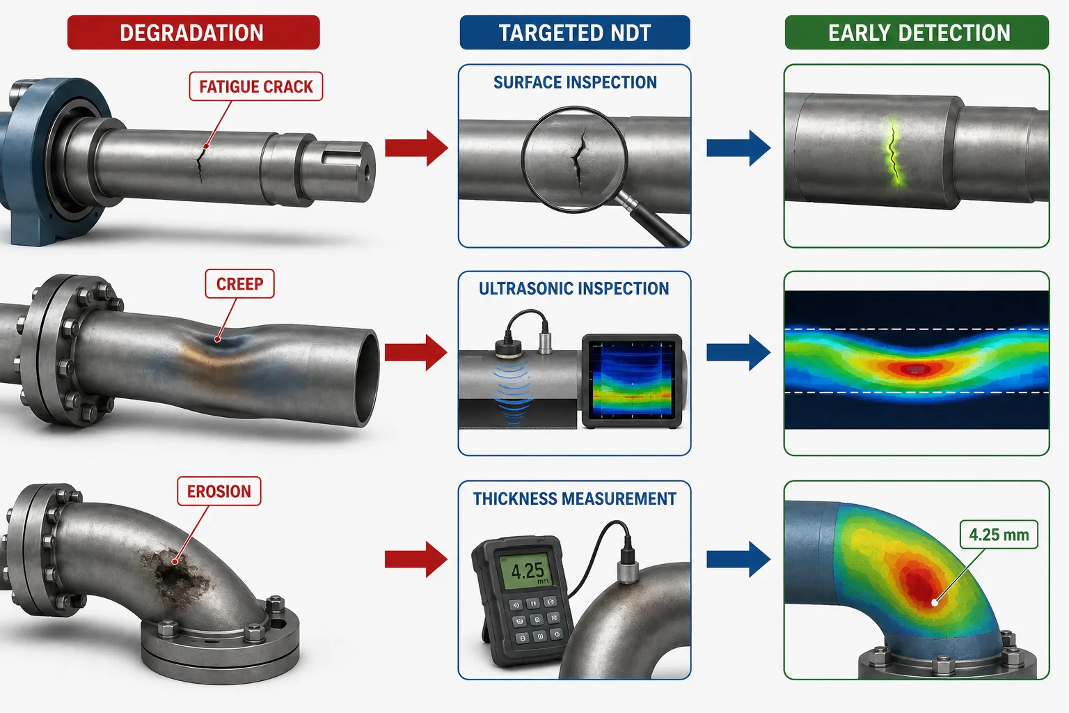
Physical degradation occurs when the condition or performance of a mechanical component progressively deteriorates during manufacturing, operation, maintenance or service.
The degradation mechanism depends on factors such as:
- Applied mechanical loads.
- Cyclic loading.
- Temperature.
- Pressure.
- Fluid velocity.
- Chemical environment.
- Surface condition.
- Material properties.
- Manufacturing quality.
- Operating duration.
- Maintenance practices.
- Environmental exposure.
Common degradation mechanisms include:
- Fatigue cracking.
- Creep deformation.
- Erosion.
- Corrosion.
- Wear.
- Fretting.
- Thermal damage.
- Surface cracking.
- Material loss.
- Distortion.
- Delamination in relevant materials.
Different degradation mechanisms produce different physical indications. Consequently, the inspection method must be selected according to the type of defect that is reasonably expected.
What Is Targeted Non-Destructive Inspection?
Non-destructive inspection refers to techniques used to examine materials, components or assemblies without causing unacceptable damage to their future serviceability.
Targeted NDT means that inspection resources are directed towards:
- Known high-risk locations.
- Areas with high stress concentration.
- Previous defect locations.
- Welded joints.
- Heat-affected zones.
- High-temperature regions.
- High-velocity flow areas.
- Areas exposed to cyclic loading.
- Locations identified through FMEA.
- Components showing abnormal operating trends.
This targeted approach is more effective than applying identical inspection methods and frequencies to every component regardless of risk.
Key Concepts and Definitions
| Key concept | Definition | Relevance to mechanical QA/QC |
|---|---|---|
| Degradation | Progressive deterioration of material or component condition | Indicates declining mechanical integrity |
| Fatigue cracking | Crack development caused by repeated or cyclic loading | Important for shafts, welds, gears and rotating parts |
| Creep | Time-dependent deformation under sustained stress, generally at elevated temperature | Important for high-temperature components |
| Erosion | Progressive material removal caused by fluid, particles or mechanical action | Important in piping, valves and flow equipment |
| NDT | Inspection performed without unacceptable damage to the component | Enables inspection while preserving serviceability |
| Targeted inspection | Inspection directed towards specific risk locations | Improves efficiency and defect detection |
| Surface defect | Discontinuity located at or near the component surface | Often detectable through surface examination methods |
| Internal defect | Discontinuity located beneath the component surface | May require volumetric inspection |
| Indication | Signal or visual response produced during an inspection | Requires technical interpretation |
| Acceptance criterion | Defined requirement used to determine whether an indication is acceptable | Supports objective decisions |
| Monitoring | Repeated assessment of condition over time | Helps identify degradation trends |
| Remaining integrity | Current ability of a component to continue performing its function | Supports service decisions |
Recognising Fatigue Cracking
Fatigue cracking develops when a component is subjected to repeated or fluctuating stresses over time. The applied stress may remain below the material’s static strength, yet repeated cycling can initiate and propagate a crack.
Fatigue is particularly important in:
- Rotating shafts.
- Gear components.
- Couplings.
- Welded structures.
- Pressure-containing components.
- Crankshafts.
- Connecting rods.
- Mechanical linkages.
- Components subject to vibration.
The fatigue process can broadly be understood as:
Cyclic loading → crack initiation → crack propagation → reduced section → potential failure
The early stages can be difficult to detect visually because cracks may be small and located in highly stressed areas.
Typical Causes of Fatigue Cracking
Potential fatigue contributors include:
- Repeated loading.
- Vibration.
- Stress concentration.
- Sharp geometric transitions.
- Keyways.
- Weld toes.
- Surface damage.
- Poor surface finish.
- Misalignment.
- Repeated start-stop cycles.
- Torque fluctuations.
- Pressure cycling.
FMEA can help identify these locations as priority inspection zones.
Where to Look for Fatigue Cracks
Targeted inspection should focus on areas where cyclic stresses are concentrated.
Examples include:
- Shaft shoulders.
- Keyways.
- Weld toes.
- Fillet transitions.
- Gear teeth.
- Thread roots.
- Bolt holes.
- Coupling interfaces.
- Abrupt geometry changes.
- Areas with previous repairs.
The inspection location should be based on engineering understanding of the load path and likely crack initiation mechanism.
Non-Destructive Methods for Detecting Fatigue Cracking
Several NDT methods may be appropriate depending on the component and expected defect.
Visual Inspection
Visual examination is often the first inspection stage.
It can identify:
- Surface cracks that are large enough to see.
- Corrosion.
- Surface damage.
- Deformation.
- Wear.
- Leakage.
- Discolouration.
- Distortion.
However, visual inspection has limitations. Very small cracks, subsurface defects and defects hidden beneath coatings may not be detectable.
Liquid Penetrant Testing
Liquid penetrant testing is commonly used to identify surface-breaking discontinuities in suitable non-porous materials.
The process generally involves:
- Preparing and cleaning the surface.
- Applying penetrant.
- Allowing appropriate dwell time.
- Removing excess penetrant.
- Applying developer where required.
- Examining the resulting indications.
- Evaluating the indication against applicable criteria.
- Recording the findings.
It can be useful for detecting fine surface-breaking cracks around:
- Welds.
- Machined components.
- Shafts.
- Fillets.
- Complex surfaces.
Magnetic Particle Testing
Magnetic particle testing can identify surface and near-surface discontinuities in suitable ferromagnetic materials.
It is particularly useful for components such as:
- Carbon steel shafts.
- Ferromagnetic fabricated components.
- Welded mechanical structures.
- Forged components.
The method uses a magnetic field and suitable particles to reveal discontinuities that interrupt the magnetic field.
Ultrasonic Testing
Ultrasonic testing uses high-frequency sound waves to examine material condition and identify internal or surface-connected discontinuities.
It can be useful for:
- Weld inspection.
- Thickness measurement.
- Crack detection.
- Internal discontinuity assessment.
- Remaining wall-thickness evaluation.
Ultrasonic techniques can provide valuable information where a visual or surface-only method is insufficient.
Radiographic Testing
Radiographic examination can provide information about internal discontinuities by producing an image associated with variations in material attenuation.
Depending on the application, it can identify certain internal discontinuities such as:
- Porosity.
- Inclusions.
- Certain volumetric weld defects.
The technique requires controlled application and competent interpretation.
Recognising Creep Degradation
Creep is time-dependent deformation that can occur when a material is exposed to sustained stress, particularly at elevated temperature.
Creep is especially relevant to:
- High-temperature piping.
- Pressure-containing equipment.
- Boilers.
- High-temperature process equipment.
- Turbine components.
- Furnace components.
- Hot mechanical structures.
Creep can gradually cause:
- Dimensional changes.
- Permanent deformation.
- Localised damage.
- Cracking.
- Loss of load-carrying capacity.
Unlike a sudden overload, creep damage may develop over an extended period.
Early Indicators of Creep
Potential signs include:
- Permanent dimensional change.
- Bulging.
- Localised deformation.
- Distortion.
- Wall-thickness changes.
- Surface cracking.
- Changes around welds.
- Increasing deformation over time.
The significance of these indicators depends on the component, material, temperature, stress and service history.
Targeted Inspection for Creep
A targeted creep inspection programme may focus on:
- High-temperature zones.
- Welded joints.
- Areas with high stress.
- Locations with previous deformation.
- Components with long service exposure.
- Regions where temperature is highest.
Useful inspection activities may include:
- Dimensional measurement.
- Visual inspection.
- Ultrasonic examination.
- Surface examination.
- Metallurgical assessment where appropriate.
- Thickness measurement.
- Replication or other specialist techniques where specified by the applicable integrity programme.
Understanding Erosion
Erosion occurs when material is progressively removed from a surface through mechanical interaction with a moving fluid, particles or another material.
Erosion can be significant in:
- Pipe bends.
- Elbows.
- Valve internals.
- Pump components.
- Impellers.
- Nozzles.
- Flow restrictions.
- Areas with high fluid velocity.
Erosion may become more severe where:
- Flow velocity increases.
- Solid particles are present.
- Fluid direction changes abruptly.
- Turbulence is high.
- Materials are relatively susceptible to material loss.
Early Signs of Erosion
Potential indicators include:
- Localised wall-thickness reduction.
- Pitting-like material loss.
- Surface roughening.
- Reduced component dimensions.
- Localised thinning at bends.
- Increased leakage risk.
- Changes in flow performance.
Thickness monitoring can be particularly useful for tracking erosion-related material loss.
Ultrasonic Thickness Measurement for Erosion
Ultrasonic thickness measurement can provide quantitative evidence of wall-thickness condition.
The basic concept involves:
- Selecting measurement locations.
- Establishing a baseline thickness.
- Taking repeat measurements.
- Comparing measurements over time.
- Calculating or estimating the degradation trend where appropriate.
- Evaluating remaining thickness against applicable requirements.
For example, if a pipe section shows a progressive decrease in measured wall thickness, the inspection team should determine whether the trend is consistent with erosion, corrosion or another degradation mechanism.
Baseline Inspection
A baseline inspection establishes an initial condition against which future results can be compared.
A good baseline should document:
- Component identity.
- Inspection location.
- Measurement method.
- Material where relevant.
- Initial measurement.
- Date.
- Equipment condition.
- Relevant operating conditions.
Without a reliable baseline, identifying gradual degradation becomes more difficult.
Trend-Based Degradation Assessment
Repeated inspection results can be more valuable than a single measurement because they allow engineers to identify trends.
For example:
| Inspection period | Measured wall thickness |
|---|---|
| Initial inspection | 12.0 mm |
| Year 1 | 11.7 mm |
| Year 2 | 11.4 mm |
| Year 3 | 11.1 mm |
The sequence indicates progressive material loss.
The engineer should not automatically assume the loss is caused by erosion. Other mechanisms, measurement uncertainty and inspection conditions should also be considered.
The key principle is:
Single measurement = condition snapshot
Repeated measurements = degradation trend
Selecting the Correct NDT Method
The inspection method should match the expected defect mechanism.
For surface-breaking cracks
Potential methods include:
- Visual examination.
- Liquid penetrant testing.
- Magnetic particle testing for suitable ferromagnetic materials.
For internal defects
Potential methods include:
- Ultrasonic testing.
- Radiographic testing.
For wall-thickness loss
Potential methods include:
- Ultrasonic thickness measurement.
- Appropriate dimensional inspection.
For deformation
Potential methods include:
- Dimensional measurement.
- Visual inspection.
- Geometric surveys where appropriate.
Selecting an unsuitable method may produce false confidence because the inspection may not be capable of detecting the relevant defect.
Risk-Based Targeting of Inspection Locations
A risk-based approach directs greater attention to components where failure consequences or degradation likelihood are higher.
Priority locations may include:
- High-stress areas.
- High-temperature areas.
- High-pressure boundaries.
- Areas exposed to aggressive fluids.
- Components with repeated cyclic loading.
- Previously failed components.
- Locations showing abnormal trends.
- Areas with known manufacturing weaknesses.
This makes inspection resources more effective.
Linking FMEA with NDT
FMEA and targeted NDT work particularly well together.
For example:
FMEA identifies: fatigue cracking as a significant failure mode.
FMEA identifies cause: cyclic loading at a shaft shoulder.
NDT strategy: targeted surface inspection of the shaft shoulder.
Monitoring strategy: vibration trending.
Preventive action: investigate alignment and loading.
This demonstrates how predictive analysis can directly inform inspection planning.
Recognising Degradation Through Condition Trends
Inspection results should ideally be considered alongside operating data.
Relevant trends may include:
- Increasing vibration.
- Increasing temperature.
- Increasing leakage.
- Increasing pressure drop.
- Reducing flow.
- Increasing wall loss.
- Increasing dimensional deviation.
- Increasing maintenance frequency.
When several indicators change simultaneously, the likelihood of developing degradation may increase.
For example:
Increasing vibration + bearing temperature + lubrication deterioration = stronger indication of possible bearing degradation
The combination of evidence can be more informative than any single measurement.
Practical Example: Fatigue Crack in a Rotating Shaft
A rotating shaft has operated continuously for several years. Vibration data show a gradual increase, although the shaft remains within normal operating speed.
FMEA identifies the shaft shoulder as a potential fatigue initiation location because of the geometry and repeated loading.
A targeted surface inspection is therefore conducted.
The inspection identifies a small surface indication near the shoulder.
The QA/QC response should involve:
- Recording the indication.
- Confirming its characteristics using the appropriate inspection method.
- Comparing it with applicable acceptance criteria.
- Reviewing operating history.
- Assessing fatigue significance.
- Escalating for engineering evaluation where required.
The important point is that the defect was identified before a major shaft failure occurred.
Practical Example: Creep in High-Temperature Piping
A high-temperature process line has operated for an extended period. Inspection records show slight dimensional changes in a high-temperature section.
The engineering team identifies the area as creep-sensitive because it experiences:
- Elevated temperature.
- Sustained stress.
- Long operating duration.
A targeted inspection programme is established to monitor:
- Dimensional changes.
- Wall condition.
- Surface cracking.
- Weld regions.
Repeated measurements provide evidence of whether deformation is stable or increasing.
Practical Example: Erosion at a Pipe Elbow
A process line transports fluid containing abrasive particles. The line contains several changes in flow direction.
Inspection data show that an elbow is experiencing faster wall-thickness reduction than straight sections.
The QA/QC team identifies the elbow as an erosion-prone location.
Actions may include:
- Increased thickness-monitoring frequency.
- Review of flow velocity.
- Examination of particle concentration.
- Evaluation of material suitability.
- Review of elbow geometry.
- Engineering assessment of remaining thickness.
This demonstrates how targeted NDT can focus resources on the locations most likely to degrade.
Inspection Planning Process
Step 1: Understand the Equipment
Identify:
- Component.
- Material.
- Function.
- Operating conditions.
- Service history.
Step 2: Identify Degradation Mechanisms
Consider:
- Fatigue.
- Creep.
- Erosion.
- Corrosion.
- Wear.
- Thermal degradation.
Step 3: Identify High-Risk Locations
Review:
- Stress concentrations.
- Welds.
- High-temperature areas.
- Flow restrictions.
- Previous defect locations.
Step 4: Select Suitable NDT Methods
Match the method to the suspected defect.
Step 5: Establish Baseline Data
Record:
- Initial condition.
- Measurements.
- Inspection method.
- Location.
Step 6: Perform Targeted Inspection
Conduct the inspection using appropriate procedures and competent personnel.
Step 7: Interpret Indications
Determine:
- Location.
- Size where applicable.
- Type.
- Significance.
- Trend.
Step 8: Compare with Acceptance Criteria
Determine whether the indication is:
- Acceptable.
- Requires monitoring.
- Requires further examination.
- Requires repair.
- Requires replacement.
- Requires engineering assessment.
Step 9: Establish Follow-Up
Where degradation is identified:
- Increase monitoring.
- Investigate the cause.
- Evaluate remaining integrity.
- Implement preventive controls.
Step 10: Update the Risk Assessment
Inspection findings should feed back into:
- FMEA.
- Maintenance plans.
- Inspection plans.
- Risk assessments.
- Engineering specifications.
Importance of Competent NDT Personnel
NDT results are only as reliable as the inspection process and interpretation supporting them.
Inspection quality depends on:
- Appropriate method selection.
- Correct equipment.
- Suitable procedures.
- Adequate surface preparation.
- Correct calibration.
- Appropriate sensitivity.
- Competent personnel.
- Correct interpretation.
- Traceable reporting.
A technically unsuitable inspection method or poorly controlled inspection can produce false confidence.
Acceptance Criteria and Engineering Judgement
Finding an indication does not automatically mean that a component must be rejected.
The significance of an indication depends on:
- Defect type.
- Defect size.
- Defect location.
- Component function.
- Loading.
- Material.
- Operating environment.
- Applicable acceptance criteria.
- Consequence of failure.
The inspection result should therefore be assessed against the applicable technical and engineering requirements.
Common Inspection Errors
Common weaknesses include:
- Selecting an inspection method without considering the failure mechanism.
- Inspecting only easily accessible locations.
- Ignoring previous defect locations.
- Failing to establish baseline measurements.
- Comparing measurements taken under inconsistent conditions.
- Ignoring measurement uncertainty.
- Treating every indication as a critical defect.
- Treating every indication as harmless.
- Failing to trend results.
- Ignoring changes in operating conditions.
- Poor inspection documentation.
- Failing to update risk assessments after findings.
Benefits of Targeted NDT
A properly designed targeted inspection programme can:
- Detect degradation at an early stage.
- Reduce unexpected component failures.
- Improve mechanical reliability.
- Support predictive maintenance.
- Reduce unnecessary component replacement.
- Improve inspection efficiency.
- Focus resources on critical areas.
- Support evidence-based decisions.
- Identify developing fatigue damage.
- Monitor creep-sensitive equipment.
- Detect material loss from erosion.
- Improve asset integrity management.
- Support continuous improvement.
- Reduce unplanned downtime.
Case Study: Integrated Degradation Detection
Background
A manufacturing plant operates a high-speed rotating assembly connected to a process pipeline. The system has operated for several years under variable loading conditions.
Recent operating data show:
- Gradually increasing vibration.
- Slightly increased bearing temperature.
- Occasional changes in operating load.
Risk Identification
The FMEA identifies several potential failure mechanisms:
- Fatigue cracking.
- Bearing degradation.
- Misalignment.
- Coupling deterioration.
The shaft shoulder and coupling interface are identified as high-risk locations.
Targeted Inspection
The inspection team conducts appropriate surface and dimensional examinations at the identified locations. Additional condition-monitoring data are reviewed.
A small indication is identified near a high-stress shaft transition.
Engineering Assessment
The finding is evaluated according to:
- Location.
- Size.
- Loading.
- Material.
- Operating history.
- Applicable acceptance criteria.
The team determines that further engineering evaluation is required before continued unrestricted operation.
Preventive Measures
Potential controls include:
- Detailed defect characterisation.
- Temporary operating controls where justified.
- Increased vibration monitoring.
- Alignment verification.
- Repair or replacement based on engineering assessment.
- Review of the FMEA.
Lesson from the Case
The case demonstrates the value of combining predictive risk analysis with targeted NDT. The physical indication alone does not tell the complete story. The significance becomes clearer when inspection results are combined with loading history, condition trends and failure-mode analysis.
Integrating NDT Findings into Continuous Improvement
NDT findings should not remain isolated within inspection reports. They should be fed into the wider quality and reliability system.
Useful actions include:
- Updating defect databases.
- Revising inspection frequencies.
- Updating FMEA rankings.
- Revising maintenance strategies.
- Reviewing manufacturing processes.
- Improving component design.
- Investigating root causes.
- Monitoring recurring degradation.
This creates a feedback cycle:
Inspection → Finding → Analysis → Corrective action → Monitoring → Verification
Final Professional Perspective
Recognising early physical degradation requires engineers to understand both the failure mechanism and the capabilities of the inspection method used to detect it. Fatigue cracking, creep and erosion have different causes, different physical manifestations and different inspection requirements. Consequently, there is no single NDT technique that can reliably identify every type of degradation in every component.
The most effective approach is targeted and risk-based. FMEA, operating data, historical inspection results and condition-monitoring trends can be used to identify where degradation is most likely to occur. Appropriate NDT methods can then be directed towards those locations to establish reliable evidence of component condition. Repeated inspection provides additional value because it allows engineers to distinguish an isolated condition from a developing degradation trend.
Conclusion
Targeted non-destructive inspection provides an essential mechanism for identifying early signs of mechanical degradation before they develop into major failures. Fatigue cracking, creep and erosion can progressively reduce component integrity, but their early indicators can often be detected through appropriate combinations of visual examination, surface inspection, ultrasonic techniques, thickness measurements, radiographic examination and other specialised methods. The correct inspection method must always be matched to the expected degradation mechanism, component material and operating environment.
For mechanical QA/QC and reliability professionals, the greatest value comes from combining NDT with predictive risk assessment, FMEA, historical inspection data and operational condition monitoring. This enables inspection resources to be concentrated on high-risk locations, degradation trends to be identified earlier, and engineering decisions to be supported by objective evidence. When inspection findings are systematically fed back into maintenance, design, process control and continuous-improvement activities, organisations can reduce unexpected failures, extend reliable component service, improve asset integrity and maintain consistently high mechanical quality and safety standards.
3. Design a Proactive Preventive Action Plan to Modify Equipment Setups or Operating Guidelines Before a Predicted Mechanical Failure Occurs
Proactive preventive action is a fundamental principle of modern mechanical QA/QC and reliability management. Instead of waiting for a mechanical component to fail and then responding to the resulting defect, production interruption, equipment damage or safety concern, a proactive approach uses available engineering evidence to identify developing risks and implement controls before failure occurs. In complex industrial environments, this requires the integration of inspection findings, condition-monitoring data, FMEA results, maintenance history, operating trends, engineering calculations and quality records.
A proactive preventive action plan translates predicted failure risks into practical engineering controls. These controls may involve modifying equipment setup, adjusting operating parameters, improving alignment, changing lubrication practices, revising inspection intervals, introducing additional monitoring, modifying maintenance instructions, or updating operating guidelines. The objective is not simply to make equipment operate differently; it is to reduce the likelihood of a specific predicted failure while maintaining required production, quality, safety and performance requirements.
For mechanical QA/QC professionals, the quality of a preventive action plan depends on the strength of the evidence supporting the predicted failure, the suitability of the proposed intervention, clear ownership of actions, controlled implementation and verification of effectiveness. A technically sound action that is poorly implemented may introduce new risks. Therefore, preventive action must be treated as a controlled engineering change rather than an informal operational adjustment.
Understanding Proactive Preventive Action
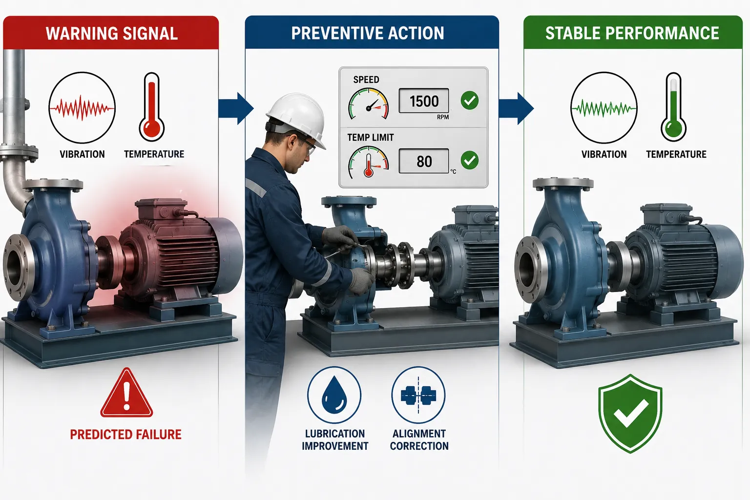
A proactive preventive action is a planned intervention introduced because available evidence indicates that a potential problem could occur if existing conditions continue.
The basic logic is:
Evidence → Predicted failure → Risk assessment → Preventive action → Controlled implementation → Verification
Examples include:
- Increasing vibration indicates developing shaft or bearing problems.
- Repeated overheating indicates inadequate cooling or lubrication.
- Progressive wall-thickness loss indicates potential future loss of containment.
- Increasing tool wear predicts dimensional defects.
- Repeated coupling misalignment predicts premature bearing or shaft damage.
- Repeated pressure surges indicate a potential pressure-related failure.
- Increasing fatigue indications suggest the need for intervention before crack growth becomes critical.
The intervention should occur before the predicted failure reaches an unacceptable condition.
Purpose of a Preventive Action Plan
A preventive action plan provides a structured method for controlling identified mechanical risks.
Its purposes include:
- Preventing predicted component failure.
- Reducing defect recurrence.
- Protecting equipment integrity.
- Maintaining production reliability.
- Reducing unplanned downtime.
- Controlling operating risks.
- Improving maintenance effectiveness.
- Protecting product quality.
- Establishing clear responsibilities.
- Providing traceable evidence of action.
- Verifying whether the intervention worked.
A strong plan connects each action directly to an identified failure mechanism rather than introducing generic maintenance activities without technical justification.
Key Concepts and Definitions
| Key concept | Definition | Mechanical QA/QC application |
|---|---|---|
| Proactive action | Intervention taken before a predicted failure occurs | Prevents known or developing mechanical risks |
| Preventive action | Action designed to reduce the likelihood or consequence of a potential failure | Modifies equipment, process or operating controls |
| Predicted failure | Failure identified as credible through evidence or analysis | Provides the basis for intervention |
| Failure mechanism | Physical process through which failure develops | Fatigue, wear, creep, erosion, overheating |
| Equipment setup | Physical or operational configuration of equipment | Alignment, clearances, lubrication, mounting |
| Operating guideline | Defined instruction for operating equipment safely and effectively | Limits speed, load, pressure or temperature |
| Risk control | Measure used to reduce identified risk | Monitoring, adjustment, redesign or maintenance |
| Trigger point | Defined condition that initiates an action | Vibration, temperature or thickness threshold |
| Corrective action | Action taken to address an existing problem | Removes an identified nonconformity |
| Preventive action | Action taken to prevent a potential problem | Controls a predicted failure |
| Verification | Confirmation that an action was implemented correctly | Inspection, measurement or review |
| Effectiveness review | Assessment of whether the action achieved its intended result | Compares post-action performance with baseline |
Difference Between Reactive and Proactive Approaches
Reactive maintenance generally follows this sequence:
Failure → Investigation → Repair → Restart
Although this approach can be necessary when unexpected failures occur, it provides limited opportunity to prevent the initial event.
A proactive approach follows:
Warning indicator → Analysis → Risk assessment → Preventive action → Verification
For example, if a bearing temperature increases gradually, a reactive approach may wait until the bearing fails. A proactive approach investigates the temperature trend, determines the likely cause, and introduces an intervention before failure.
Possible interventions may include:
- Lubrication correction.
- Alignment verification.
- Load reduction.
- Cooling improvement.
- Bearing inspection.
- Increased monitoring.
Identifying the Predicted Failure
The first stage in designing the action plan is to define exactly what failure is being predicted.
The description should identify:
- Component.
- Failure mode.
- Location.
- Evidence.
- Operating condition.
- Expected consequence.
For example:
Weak statement:
“Bearing may fail.”
Stronger engineering statement:
“Bearing temperature has increased progressively over three inspection periods while vibration has also increased, indicating a developing lubrication, alignment or bearing-condition problem that could lead to premature bearing failure.”
The stronger statement provides a basis for action.
Sources of Evidence for Predictive Action
A preventive action plan should be based on reliable technical evidence.
Potential sources include:
- FMEA results.
- Inspection reports.
- NDT findings.
- Vibration measurements.
- Temperature records.
- Pressure records.
- Historical breakdown data.
- Dimensional inspection results.
- Lubrication records.
- Maintenance history.
- Material test results.
- Production quality data.
- Operator observations.
- Equipment performance data.
The greater the consequence of the predicted failure, the stronger the evidence and engineering justification should generally be.
Establishing the Failure Mechanism
Before selecting an intervention, the team should understand why failure is predicted.
Possible mechanisms include:
Fatigue
Repeated cyclic loading can initiate and propagate cracks.
Potential controls include:
- Reducing cyclic loads.
- Improving alignment.
- Controlling vibration.
- Reviewing component geometry.
- Increasing inspection frequency.
Wear
Repeated mechanical contact can progressively remove material.
Potential controls include:
- Improving lubrication.
- Controlling contact conditions.
- Replacing worn components.
- Improving material selection.
- Monitoring dimensional loss.
Creep
Long-term exposure to elevated temperature and sustained stress can cause deformation.
Potential controls include:
- Reducing operating temperature where feasible.
- Controlling loads.
- Monitoring deformation.
- Increasing targeted inspection.
- Reviewing component suitability.
Erosion
High-velocity fluids or particles can progressively remove material.
Potential controls include:
- Reducing flow velocity where practicable.
- Modifying flow paths.
- Increasing wall-thickness monitoring.
- Reviewing material suitability.
- Replacing vulnerable components.
Misalignment
Misalignment can increase loads on shafts, bearings and couplings.
Potential controls include:
- Precision alignment.
- Improved mounting.
- Foundation correction.
- Alignment verification after maintenance.
Defining Preventive Action Objectives
Each action should have a clear objective.
Examples include:
- Reduce vibration to an acceptable operating range.
- Stabilise bearing temperature.
- Reduce wall-thickness loss.
- Prevent repeated coupling misalignment.
- Reduce excessive tool wear.
- Maintain dimensional capability.
- Prevent pressure excursions.
- Reduce cyclic loading.
- Improve lubrication condition.
Objectives should be measurable wherever possible.
Designing Equipment Setup Modifications
Equipment setup changes can be highly effective when the predicted failure is associated with configuration or installation conditions.
Potential setup modifications include:
- Realigning rotating equipment.
- Adjusting component clearances.
- Correcting coupling alignment.
- Improving equipment support.
- Adjusting belt or chain tension.
- Correcting bearing installation.
- Improving lubrication delivery.
- Modifying cooling arrangements.
- Improving component positioning.
- Reconfiguring flow paths.
The modification should be based on evidence rather than trial-and-error adjustment.
Example: Correcting Rotating Equipment Alignment
Suppose vibration data show a gradual increase in a rotating machine.
Inspection indicates:
- Shaft vibration increasing.
- Bearing temperature increasing.
- Coupling alignment outside the preferred condition.
The preventive action plan could include:
- Stop the equipment under controlled conditions.
- Verify alignment measurements.
- Correct alignment.
- Inspect coupling condition.
- Verify bearing condition.
- Restart under controlled conditions.
- Record vibration and temperature.
- Compare results with baseline data.
The intervention is successful only if the expected improvement is demonstrated.
Modifying Operating Guidelines
Sometimes equipment does not need immediate physical modification. The risk may be reduced by controlling how the equipment is operated.
Operating guidelines may define:
- Maximum operating speed.
- Maximum pressure.
- Maximum temperature.
- Permitted load.
- Start-up procedure.
- Shutdown procedure.
- Ramp-up rate.
- Ramp-down rate.
- Maximum vibration.
- Inspection trigger levels.
For example, if repeated pressure surges occur during start-up, a revised start-up procedure may introduce a controlled pressure increase rather than allowing rapid pressurisation.
Establishing Operating Limits
Operating limits should be based on:
- Equipment design capability.
- Manufacturer information.
- Engineering calculations.
- Plant operating conditions.
- Historical performance.
- Applicable technical requirements.
- Identified degradation mechanisms.
Limits should not simply be selected because they are convenient for production.
A limit should have a technical basis.
Trigger Points and Action Levels
A proactive action plan becomes much stronger when it defines clear trigger points.
For example:
| Indicator | Normal condition | Warning trigger | Preventive action |
|---|---|---|---|
| Vibration | Stable baseline | Increasing trend | Inspect alignment and bearings |
| Bearing temperature | Stable | Progressive increase | Review lubrication and loading |
| Wall thickness | Stable | Accelerated loss | Increase inspection and assess integrity |
| Pressure | Within normal range | Repeated excursions | Review operating controls |
| Tool wear | Controlled | Rapid increase | Adjust machining parameters |
| Dimensional variation | Stable | Increasing spread | Review process parameters |
These values are illustrative. Actual limits should be established from the applicable equipment requirements, engineering basis, manufacturer information and approved plant procedures.
Prioritising Preventive Actions
Not every predicted failure requires the same level of intervention.
Priority should consider:
- Severity of failure.
- Likelihood.
- Detectability.
- Failure consequences.
- Equipment criticality.
- Production impact.
- Safety implications.
- Environmental consequences.
- Availability of alternative equipment.
High-consequence risks should receive appropriate priority even where the probability appears relatively low.
Developing an Action Ownership Structure
Each preventive action should have a clearly identified owner.
Responsibilities may include:
QA/QC Engineer
- Verify quality evidence.
- Review inspection findings.
- Confirm technical requirements.
- Monitor implementation evidence.
Mechanical Engineer
- Assess mechanical integrity.
- Confirm engineering suitability.
- Develop technical modifications.
Maintenance Engineer
- Plan equipment intervention.
- Coordinate maintenance work.
- Verify equipment condition.
Operations Team
- Implement revised operating instructions.
- Monitor operating parameters.
- Report abnormal conditions.
Reliability Engineer
- Analyse trends.
- Review failure probability.
- Evaluate effectiveness.
Supervisor
- Coordinate work execution.
- Confirm procedural compliance.
- Escalate deviations.
Creating a Controlled Action Plan
A practical preventive action register can contain:
- Action number.
- Equipment identification.
- Failure mode.
- Evidence.
- Risk level.
- Preventive action.
- Responsible person.
- Target date.
- Required shutdown.
- Verification method.
- Completion status.
- Effectiveness result.
This creates traceability between prediction and intervention.
Risk Assessment Before Implementing Changes
A preventive modification should itself be assessed for risk.
A change that solves one problem may create another.
For example, reducing pump speed may reduce vibration but also reduce required process flow.
Changing lubrication may reduce bearing temperature but introduce compatibility concerns if the lubricant is unsuitable.
Therefore, the team should consider:
- New mechanical loads.
- Process impact.
- Quality impact.
- Safety implications.
- Equipment compatibility.
- Maintenance implications.
- Production requirements.
Management of Engineering Change
Significant equipment modifications should be controlled through the organisation’s engineering or management-of-change process where applicable.
This may involve:
- Technical review.
- Drawing updates.
- Procedure revision.
- Risk assessment.
- Approval.
- Inspection.
- Testing.
- Commissioning.
- Documentation.
The purpose is to ensure that changes are properly evaluated rather than introduced informally.
Preventive Action for Fatigue Risk
Consider a rotating shaft showing increasing vibration and evidence of cyclic loading.
A proactive action plan might include:
- Verify shaft alignment.
- Inspect high-stress transitions.
- Review operating speed.
- Review torque fluctuations.
- Conduct targeted NDT.
- Establish vibration monitoring.
- Define escalation criteria.
- Review maintenance frequency.
The plan should address the underlying contributors rather than simply replacing the shaft repeatedly.
Preventive Action for Erosion Risk
For a pipe elbow showing accelerated material loss:
Potential actions include:
- Increase thickness monitoring.
- Review flow velocity.
- Review particle concentration.
- Examine flow conditions.
- Assess material suitability.
- Consider geometry modification.
- Establish minimum acceptable thickness.
- Define inspection trigger points.
The objective is to prevent loss of containment rather than simply respond after a leak occurs.
Preventive Action for Creep Risk
For high-temperature equipment showing progressive deformation:
Potential measures may include:
- Review operating temperature.
- Review sustained loads.
- Monitor dimensional changes.
- Inspect high-risk weld regions.
- Establish periodic condition assessments.
- Review remaining integrity.
- Control operating conditions within approved limits.
Creep-related interventions require careful engineering evaluation because changes in operating temperature or load may affect production requirements.
Preventive Action for Bearing Degradation
If vibration and temperature trends indicate developing bearing degradation:
Potential actions include:
- Verify lubrication condition.
- Check lubricant quantity.
- Inspect bearing installation.
- Verify shaft alignment.
- Review loading.
- Increase vibration monitoring.
- Establish temperature trigger levels.
- Plan controlled replacement if required.
The action should be proportional to the evidence and risk.
Verification of Preventive Action
Implementation alone does not prove success.
The team should establish how effectiveness will be demonstrated.
Verification may involve:
- Post-maintenance vibration measurements.
- Temperature comparison.
- Dimensional inspection.
- Pressure monitoring.
- Flow measurement.
- NDT follow-up.
- Defect-rate comparison.
- Production performance comparison.
For example:
Before intervention: vibration = increasing trend.
After intervention: vibration returns to stable baseline.
This provides stronger evidence that the intervention has addressed the predicted mechanism.
Comparing Before-and-After Data
A useful preventive action review should compare:
- Baseline condition.
- Intervention date.
- Post-intervention condition.
- Operating conditions.
- Inspection results.
- Failure indicators.
The comparison should account for changes in operating load. A component may appear improved simply because it is operating under a lower load.
Effectiveness Review
A preventive action can be classified as effective when evidence demonstrates that:
- The predicted failure risk has been reduced.
- The warning indicator has stabilised.
- The defect trend has improved.
- The underlying cause has been controlled.
- No unacceptable new risk has been introduced.
If the expected improvement does not occur, the action should be reconsidered.
Practical Case Study: Preventing a Bearing Failure
Background
A production machine uses a high-speed rotating shaft supported by bearings.
Routine monitoring identifies:
- Increasing vibration.
- Gradual temperature increase.
- Increasing lubrication contamination.
No catastrophic failure has occurred.
Predictive Assessment
The FMEA identifies bearing degradation as a significant potential failure mode.
Potential causes include:
- Lubricant contamination.
- Misalignment.
- Excessive loading.
Preventive Action Plan
The engineering team develops the following actions:
- Inspect lubrication condition.
- Replace contaminated lubricant where appropriate.
- Verify alignment.
- Inspect bearing condition.
- Increase vibration monitoring.
- Establish temperature warning levels.
- Review operating load.
Implementation
The equipment is taken through a controlled maintenance intervention. Alignment is corrected and lubrication condition is restored.
Verification
Following restart:
- Vibration decreases.
- Temperature stabilises.
- No abnormal trend is observed.
Outcome
The intervention prevents the predicted bearing failure from progressing to an unplanned breakdown.
The case demonstrates that proactive action is most effective when prediction, intervention and verification are connected.
Practical Case Study: Preventing Dimensional Defects
A machining process produces mechanical components with gradually increasing dimensional variation.
Historical data show:
- Stable dimensions initially.
- Increasing variation as tool usage increases.
- Increased rejection rates near the end of tool life.
Predicted Failure
The likely failure mechanism is excessive tool wear causing dimensional drift.
Preventive Action
The team introduces:
- Tool-life monitoring.
- Earlier tool replacement.
- Controlled machining parameters.
- Increased dimensional checks near expected tool-life limits.
Verification
The team compares:
- Pre-change rejection rate.
- Post-change rejection rate.
- Dimensional variation.
- Tool replacement frequency.
If dimensional variation decreases and rejection rates improve without unacceptable production losses, the action demonstrates effectiveness.
Preventive Action Plan Workflow
A structured workflow can be represented as:
1. Detect warning signal
↓
2. Validate evidence
↓
3. Identify predicted failure
↓
4. Determine failure mechanism
↓
5. Assess risk
↓
6. Select preventive intervention
↓
7. Review change implications
↓
8. Approve and implement
↓
9. Verify performance
↓
10. Monitor for recurrence
This workflow supports controlled and evidence-based intervention.
Common Mistakes in Preventive Action Planning
Acting on unverified data
A single abnormal reading may result from measurement error. Before changing equipment or operating procedures, the evidence should be validated.
Treating symptoms instead of causes
Reducing vibration without investigating misalignment may temporarily hide the problem.
Making uncontrolled operating changes
Operators should not introduce informal limits without engineering review where formal control is required.
Failing to define effectiveness criteria
An action without a measurable success condition is difficult to evaluate.
Ignoring production requirements
A technically effective intervention may create unacceptable production consequences if the wider system is not considered.
Failing to update documentation
Changes to equipment setup or operating limits should be reflected in relevant controlled documentation.
Benefits of Proactive Preventive Action
A well-designed preventive action plan can provide:
- Earlier failure prevention.
- Improved mechanical reliability.
- Reduced unplanned downtime.
- Lower repair costs.
- Reduced defect recurrence.
- Improved production stability.
- Better equipment availability.
- Improved maintenance planning.
- Stronger QA/QC control.
- Better risk visibility.
- More effective use of inspection resources.
- Improved operational consistency.
- Better evidence-based decision-making.
- Increased confidence in equipment performance.
Integrating Preventive Actions with FMEA
FMEA should not end when the risk ranking is completed.
The relationship can continue as:
FMEA → Failure prediction → Preventive action → Verification → FMEA update
For example, if FMEA identifies bearing overheating as a significant risk, the preventive action may involve improved lubrication and condition monitoring. After implementation, the results should be reviewed and the FMEA updated where appropriate.
This creates a continuous improvement loop.
Integrating Preventive Actions with NDT
NDT findings can also initiate preventive action.
For example:
NDT detects early crack → Engineering evaluates significance → Operating condition reviewed → Preventive action implemented → Follow-up inspection conducted
This approach ensures that NDT findings lead to meaningful risk reduction rather than simply being recorded in inspection reports.
Integrating Operating Guidelines with Quality Control
Operating guidelines should clearly communicate important controls to personnel responsible for equipment operation.
Depending on the equipment, guidelines may address:
- Start-up sequence.
- Shutdown sequence.
- Maximum pressure.
- Maximum temperature.
- Maximum speed.
- Load restrictions.
- Vibration limits.
- Inspection requirements.
- Escalation requirements.
The objective is to ensure that operating behaviour does not unintentionally accelerate the predicted failure mechanism.
Professional Decision-Making Principles
When designing preventive action, engineers should consider five fundamental questions:
Is the evidence reliable?
Confirm that the data are accurate, representative and sufficiently consistent.
Is the predicted failure credible?
Connect the observed trend to a technically plausible failure mechanism.
Is the proposed action appropriate?
The intervention should address the underlying cause or meaningfully reduce risk.
Could the intervention introduce another risk?
Consider system-level effects.
How will effectiveness be demonstrated?
Define measurable evidence before implementing the action.
Quality Records and Traceability
Preventive action should be supported by appropriate records.
Records may include:
- Inspection reports.
- Trend graphs.
- NDT reports.
- Maintenance records.
- Engineering calculations.
- Risk assessments.
- Revised procedures.
- Equipment setup records.
- Photographic evidence where appropriate.
- Verification results.
- Effectiveness review.
Traceability enables future engineering teams to understand why the action was taken and whether it achieved the intended result.
Conclusion
A proactive preventive action plan transforms mechanical failure prediction into practical engineering intervention. By combining FMEA, NDT findings, condition-monitoring data, historical inspection records and operating trends, QA/QC and reliability teams can identify credible failure mechanisms before they result in equipment breakdown or significant mechanical defects. Preventive actions may involve equipment realignment, lubrication improvement, operating-limit adjustment, inspection-frequency changes, condition monitoring, maintenance modification, process control or engineering redesign, depending on the identified risk.
The effectiveness of proactive prevention depends on disciplined implementation. Each action should have a clearly defined technical basis, responsible owner, implementation method, verification requirement and effectiveness criterion. Changes to equipment setups or operating guidelines should be properly reviewed and controlled, particularly where they may affect safety, mechanical integrity, production performance or other parts of the process. After implementation, actual performance should be compared with the baseline condition to determine whether the predicted risk has been reduced.
When this approach is embedded within a broader mechanical QA/QC and reliability system, organisations can move from reactive failure response towards predictive and preventive control. The result is better component reliability, fewer recurring defects, reduced unplanned downtime, stronger process stability and more effective use of engineering and inspection resources. Most importantly, proactive preventive action allows mechanical problems to be addressed while there is still an opportunity to control them, rather than waiting until a developing defect becomes an operational failure.
4. Establish a Tracking Log for Minor Equipment Issues to Prevent Small Operational Defects from Turning into Major System Breakdowns
Minor equipment issues are often the earliest visible indicators of developing mechanical problems. A small oil leak, intermittent vibration, unusual noise, slight temperature increase, minor dimensional deviation, loose fastener, repeated alarm, seal seepage or small change in equipment performance may appear insignificant when considered in isolation. However, when these observations are not recorded, investigated and followed through to closure, they can develop into progressive degradation, recurring defects, unplanned downtime and major mechanical failure.
A structured equipment issue tracking log provides a practical mechanism for capturing these early warning signals and ensuring that they receive appropriate technical attention. The purpose is not to create unnecessary paperwork or record every insignificant observation without evaluation. Instead, the tracking log should create a controlled link between observation, technical assessment, action, responsibility, verification and closure. This enables QA/QC, maintenance, reliability and operations teams to identify patterns that might otherwise remain hidden.
For mechanical QA/QC professionals, an effective minor-issue tracking system is particularly valuable because many serious failures develop through a sequence of smaller events. A bearing may initially show a small temperature increase before vibration develops. A seal may begin with minor seepage before leakage becomes significant. A coupling may develop slight misalignment before producing excessive vibration. A pipe may show a small localised thickness reduction before material loss becomes critical. Recording these conditions systematically allows engineering teams to intervene while the problem is still manageable.
Understanding Equipment Issue Tracking
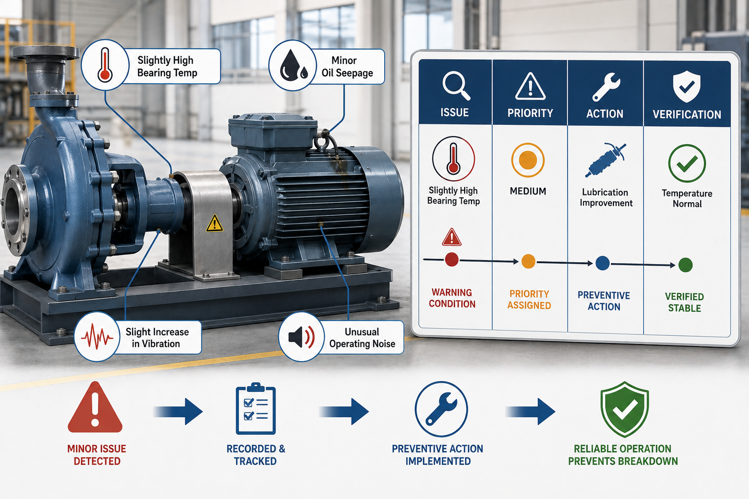
An equipment issue tracking log is a controlled record used to document minor abnormalities, observations, defects, trends and emerging equipment concerns.
The tracking process can be represented as:
Observation → Recording → Classification → Assessment → Action → Verification → Closure → Trend Review
Each stage is important.
Simply recording an issue does not prevent failure. The organisation must ensure that the issue is assessed, assigned to an appropriate person, addressed within a suitable timeframe and verified after action.
A good tracking log should therefore answer six fundamental questions:
- What happened?
- Where did it happen?
- How significant is it?
- What could it indicate?
- Who is responsible for investigating it?
- Has the issue been resolved and verified?
Purpose of a Minor Equipment Issue Tracking Log
The primary purpose is to prevent small defects from being lost within routine operational activity.
A tracking log can:
- Capture early warning signs.
- Prevent repeated issues from being forgotten.
- Identify recurring defects.
- Support preventive maintenance.
- Improve communication between teams.
- Provide traceability.
- Prioritise engineering actions.
- Support root-cause analysis.
- Identify developing degradation.
- Provide evidence for reliability decisions.
- Reduce unplanned failures.
- Support continuous improvement.
The system should distinguish between an observation that requires routine monitoring and a condition that requires immediate engineering intervention.
Key Concepts and Definitions
| Key concept | Definition | Mechanical QA/QC application |
|---|---|---|
| Minor issue | A small abnormality that does not currently represent major failure | Early warning requiring assessment or monitoring |
| Equipment defect | Condition that deviates from an expected requirement | Supports corrective or preventive action |
| Abnormal condition | Operating state outside normal expected behaviour | May indicate developing degradation |
| Tracking log | Controlled record of identified issues and actions | Provides visibility and traceability |
| Issue owner | Person responsible for progressing the issue | Prevents unresolved items being overlooked |
| Priority | Relative importance assigned to an issue | Helps allocate resources appropriately |
| Escalation | Movement of an issue to a higher level of attention | Used when risk or severity increases |
| Corrective action | Action addressing an identified existing problem | Removes or controls an observed defect |
| Preventive action | Action designed to reduce future failure likelihood | Prevents recurrence or escalation |
| Verification | Evidence that an action was completed correctly | Confirms technical completion |
| Closure | Formal confirmation that an issue has been adequately resolved | Prevents premature completion |
| Trend | Pattern of repeated or changing observations | Helps identify developing failures |
| Recurrence | Reappearance of a similar issue after previous action | Indicates that root cause may remain unresolved |
What Should Be Recorded?
A tracking log should contain sufficient information to support meaningful assessment.
Typical fields include:
- Issue identification number.
- Equipment identification.
- Location.
- Date and time.
- Person reporting the issue.
- Description of condition.
- Operating condition.
- Initial severity.
- Potential consequence.
- Immediate action.
- Assigned owner.
- Target completion date.
- Investigation findings.
- Corrective action.
- Preventive action.
- Verification result.
- Closure date.
- Recurrence status.
The level of detail should be proportionate to the issue. A minor observation does not require a lengthy technical report, but it should contain enough information to allow another competent person to understand what occurred.
Examples of Minor Equipment Issues
Potential issues include:
- Slight oil seepage.
- Small coolant leak.
- Unusual vibration.
- Slightly increased bearing temperature.
- Loose fastener.
- Minor surface corrosion.
- Small seal deterioration.
- Abnormal noise.
- Repeated minor alarm.
- Slight dimensional deviation.
- Increased lubrication consumption.
- Small pressure fluctuation.
- Reduced equipment efficiency.
- Intermittent operating instability.
- Small wall-thickness change.
The presence of a minor issue does not automatically mean that a major failure will occur. The purpose of tracking is to ensure that the condition is evaluated rather than ignored.
Why Minor Issues Matter
Mechanical failure is often progressive.
For example:
Minor seal seepage → seal deterioration → lubricant loss → bearing lubrication problem → temperature increase → bearing damage → equipment shutdown
Similarly:
Slight misalignment → increased vibration → bearing loading → accelerated wear → shaft damage → major breakdown
Tracking provides an opportunity to intervene earlier in these sequences.
Difference Between Observation and Failure
A tracking system should distinguish between an observation and an established failure.
An observation may be:
- “Bearing temperature appears higher than usual.”
A measured condition may be:
- “Bearing temperature increased from the established baseline.”
A failure may be:
- “Bearing has lost functional integrity and requires replacement.”
This distinction is important because premature classification can either overstate or understate risk.
Establishing a Reporting Process
The tracking system should make it easy for personnel to report minor issues.
A practical reporting process is:
Step 1: Observe
Personnel identify an abnormal condition.
Step 2: Record
The observation is entered into the tracking log.
Step 3: Validate
A competent person confirms the condition where necessary.
Step 4: Classify
The issue is assigned an appropriate priority.
Step 5: Assess
The potential consequence and likely cause are considered.
Step 6: Assign
A responsible person receives the action.
Step 7: Act
The required corrective or preventive action is completed.
Step 8: Verify
The equipment condition is checked after intervention.
Step 9: Close
The issue is formally closed when the evidence supports closure.
Step 10: Trend
Repeated issues are analysed to identify wider problems.
Prioritising Minor Issues
Not every minor issue has the same risk.
A simple prioritisation approach may consider:
- Severity.
- Likelihood of escalation.
- Equipment criticality.
- Detectability.
- Historical recurrence.
- Operating conditions.
- Potential safety consequences.
- Production impact.
For example, a small cosmetic scratch on a non-critical protective cover may be low priority, while a small oil leak from a high-speed bearing assembly may require immediate assessment.
Suggested Issue Classification
A practical classification system may include:
Low priority
Suitable for routine action or monitoring.
Examples:
- Minor cosmetic deterioration.
- Small non-critical surface defect.
- Low-impact housekeeping issue.
Medium priority
Requires defined corrective action within an established timeframe.
Examples:
- Repeated minor leakage.
- Increasing vibration trend.
- Deteriorating seal condition.
- Repeated abnormal temperature.
High priority
Requires urgent technical assessment.
Examples:
- Rapidly increasing vibration.
- Significant temperature rise.
- Pressure-boundary concern.
- Evidence of crack development.
- Rapid material loss.
The exact classification criteria should be defined by the organisation’s risk-management system.
Creating an Effective Tracking Log
A simple structure can be developed around five stages:
Identify
Capture the abnormal condition.
Evaluate
Determine significance and possible causes.
Control
Implement immediate measures where necessary.
Resolve
Complete corrective or preventive action.
Learn
Review recurring issues and update controls.
This structure keeps the system focused on action rather than documentation alone.
Example Tracking Matrix
| Issue ID | Equipment | Observation | Priority | Action | Owner | Status |
|---|---|---|---|---|---|---|
| M-001 | Pump P-01 | Increased vibration | Medium | Check alignment | Maintenance | Open |
| M-002 | Gearbox G-02 | Temperature rise | High | Inspect lubrication | Reliability | Under review |
| M-003 | Valve V-04 | Minor seepage | Medium | Inspect seal | QA/QC | Open |
| M-004 | Pipe L-08 | Surface corrosion | Low | Monitor condition | Inspection | Monitoring |
| M-005 | Motor M-03 | Unusual noise | Medium | Conduct condition check | Maintenance | Assigned |
This type of matrix provides a quick overview of unresolved conditions.
Establishing Issue Ownership
An issue should never simply be “reported to maintenance” without clear ownership.
The owner should be responsible for:
- Reviewing the issue.
- Determining required action.
- Coordinating resources.
- Updating status.
- Providing evidence of completion.
- Escalating if the condition worsens.
Ownership prevents the common problem where several departments assume that another team is dealing with the issue.
Setting Target Completion Dates
Each issue should have an appropriate target date based on risk.
A high-priority mechanical issue may require immediate intervention, while a low-risk cosmetic issue may be addressed during scheduled maintenance.
Target dates should consider:
- Risk.
- Equipment criticality.
- Availability of replacement parts.
- Required shutdown.
- Engineering assessment requirements.
- Production constraints.
Production pressure should not be allowed to justify indefinite postponement of a safety-critical action.
Escalation Criteria
The tracking system should define when a minor issue becomes a significant concern.
Escalation may be triggered by:
- Rapid deterioration.
- Increasing frequency.
- Increasing severity.
- Failure of the initial corrective action.
- New evidence of degradation.
- Safety implications.
- Loss of containment.
- Significant production impact.
- Evidence of crack growth.
- Operating conditions approaching critical limits.
For example, a small vibration increase may initially be classified as medium priority. If vibration continues increasing rapidly, the issue should be escalated.
Using Trend Analysis
The greatest value of an issue log often appears when several entries are analysed together.
Consider the following sequence:
- January: slight bearing temperature increase.
- February: minor vibration increase.
- March: increased lubrication consumption.
- April: intermittent noise.
- May: higher vibration.
Each issue may appear minor individually.
Together, however, they indicate a developing mechanical problem.
Trend analysis can therefore reveal relationships that individual issue reports cannot.
Recurring Issues
Repeated minor defects should trigger additional investigation.
Examples include:
- The same seal repeatedly leaking.
- The same bearing repeatedly overheating.
- The same coupling repeatedly becoming misaligned.
- The same pipe location repeatedly showing corrosion.
- The same machining dimension repeatedly drifting.
Recurrence can indicate:
- Inadequate corrective action.
- Incorrect diagnosis.
- Poor component selection.
- Process instability.
- Inadequate maintenance.
- Environmental factors.
- Design weakness.
Linking the Tracking Log to Root-Cause Analysis
The issue log can provide valuable evidence for root-cause investigations.
A root-cause investigation may ask:
- When did the problem first appear?
- How often has it occurred?
- Which equipment is affected?
- Under what operating conditions?
- What actions were previously taken?
- Did the issue return?
- Was the previous action effective?
This historical information can significantly improve investigation quality.
Linking the Tracking Log to FMEA
A recurring issue may reveal that an existing FMEA underestimated a failure mode.
For example:
Tracking log: repeated coupling vibration.
↓
Trend analysis: vibration increases after every maintenance intervention.
↓
Investigation: alignment procedure inconsistent.
↓
FMEA update: installation/alignment failure mode receives increased attention.
↓
Preventive action: revised alignment procedure and verification.
This creates a direct connection between operational observations and predictive risk management.
Tracking Minor Leakage
Minor leakage should never automatically be dismissed.
The assessment should consider:
- Fluid type.
- Pressure.
- Temperature.
- Location.
- Leak rate.
- Equipment criticality.
- Potential escalation.
- Environmental consequences.
A minor leak from a low-pressure non-critical system may have a different risk profile from a small leak on a high-pressure process boundary.
The tracking log ensures that the condition is visible and assessed.
Tracking Vibration
Vibration is an especially valuable early-warning indicator.
A tracking log can record:
- Equipment identification.
- Measurement location.
- Measurement date.
- Vibration value.
- Operating speed.
- Load condition.
- Previous measurement.
- Trend direction.
A progressive trend can trigger:
- Alignment inspection.
- Bearing inspection.
- Coupling assessment.
- Lubrication review.
- Increased monitoring.
Tracking Temperature Changes
Temperature trends can indicate:
- Bearing deterioration.
- Lubrication problems.
- Cooling deficiencies.
- Increased friction.
- Overloading.
- Process abnormalities.
The log should distinguish between an isolated measurement and a sustained trend.
Tracking Minor Corrosion
Minor corrosion should be recorded with:
- Location.
- Approximate affected area.
- Material.
- Environmental exposure.
- Previous inspection condition.
- Thickness measurements where relevant.
Repeated observations can indicate that corrosion controls are insufficient.
Tracking Dimensional Drift
In manufacturing environments, minor dimensional deviations may predict future quality problems.
For example:
Tool wear → dimensional drift → increasing variation → out-of-tolerance components → assembly problems
A tracking log can connect inspection results with:
- Machine.
- Tool.
- Batch.
- Operator.
- Material.
- Process parameters.
This supports early process intervention.
Practical Case Study: Small Bearing Temperature Increase
Background
A production machine operates continuously. Operators notice that one bearing appears slightly warmer than usual.
The temperature is not yet outside the permitted operating range.
Initial Tracking Entry
The issue is recorded as:
- Equipment: Bearing assembly B-12.
- Observation: Progressive temperature increase.
- Priority: Medium.
- Immediate action: Continue controlled monitoring.
- Owner: Reliability engineer.
Follow-Up
Subsequent records show:
- Temperature continuing to rise.
- Slight vibration increase.
- Increased lubrication consumption.
Investigation
The combined trend indicates a possible bearing or lubrication problem.
Preventive Action
The team:
- Inspects lubrication.
- Verifies alignment.
- Examines bearing condition.
- Increases monitoring frequency.
Result
The underlying condition is addressed before bearing seizure occurs.
The example demonstrates how a small operational observation can provide valuable time for intervention.
Practical Case Study: Repeated Minor Seal Leakage
A pump repeatedly develops minor seal seepage.
Individual maintenance activities have previously replaced the seal.
The tracking log shows that the same issue has occurred several times.
The engineering team reviews:
- Alignment.
- Shaft condition.
- Seal installation.
- Operating pressure.
- Temperature.
- Seal material compatibility.
The investigation identifies an underlying alignment issue.
The team corrects the alignment and verifies the installation.
The recurrence stops.
The key lesson is that repeated minor defects should prompt investigation of the system rather than repeated replacement of the failed component alone.
Using Digital Tracking Systems
A tracking log may be maintained using:
- Controlled spreadsheets.
- Computerised maintenance systems.
- Quality management systems.
- Asset-management platforms.
- Production dashboards.
- Digital inspection systems.
The specific technology is less important than the quality of the information and the discipline of follow-up.
A useful digital system should allow:
- Searchable records.
- Issue categorisation.
- Status tracking.
- Ownership.
- Due dates.
- Attachments.
- Trend analysis.
- Escalation.
- Closure evidence.
Quality of Data in the Tracking Log
Poor-quality data can reduce the value of the entire system.
Reports should be:
- Factual.
- Specific.
- Traceable.
- Measurable where possible.
- Time-stamped.
- Linked to equipment.
- Free from unnecessary assumptions.
Weak entry:
“Machine seems bad.”
Better entry:
“Pump P-03 shows increased vibration compared with the previous inspection; operator reports intermittent abnormal noise during operation.”
The second entry provides actionable information.
Closing an Issue Properly
An issue should not be closed merely because someone has performed an action.
Closure should confirm:
- The action was completed.
- The correct equipment was addressed.
- The underlying condition was evaluated.
- Required inspection was completed.
- Performance is acceptable.
- No significant recurrence is evident.
- Documentation is complete.
Where appropriate, post-action monitoring should be used before final closure.
Effectiveness Verification
The effectiveness review may compare:
Before action
- High vibration.
- Increased temperature.
- Recurring leakage.
After action
- Stable vibration.
- Normalised temperature.
- No further leakage.
The comparison provides evidence that the intervention worked.
Preventing the Backlog from Becoming a Risk
An equipment tracking system can become ineffective if unresolved issues accumulate.
The organisation should periodically review:
- Open issues.
- Overdue issues.
- High-priority issues.
- Recurring issues.
- Long-standing monitoring items.
- Issues without owners.
- Issues repeatedly deferred.
A growing backlog may indicate:
- Insufficient maintenance resources.
- Poor prioritisation.
- Inadequate ownership.
- Weak escalation.
- Production pressures.
- Ineffective management review.
Periodic Management Review
Management should review the overall issue-tracking system rather than examining only individual problems.
Useful indicators include:
- Number of open issues.
- Number of overdue actions.
- Average closure time.
- Recurrence rate.
- High-priority issue count.
- Repeat equipment defects.
- Preventive actions completed.
- Issues converted into major failures.
These indicators can help identify weaknesses in the maintenance and QA/QC system itself.
Key Benefits of an Equipment Issue Tracking Log
A well-managed tracking log can deliver significant benefits:
- Early identification of degradation.
- Better communication.
- Improved accountability.
- Faster intervention.
- Reduced recurring defects.
- Better maintenance planning.
- Improved equipment reliability.
- Reduced unplanned downtime.
- Stronger QA/QC traceability.
- Better trend analysis.
- Improved root-cause investigations.
- Stronger FMEA inputs.
- More effective preventive maintenance.
- Better evidence for management decisions.
Common Mistakes to Avoid
Recording issues without action
A large database of observations provides little value if no one investigates them.
Closing issues too quickly
An issue should not be closed simply because a component was replaced.
Ignoring recurring issues
Repeated minor defects are valuable evidence of systemic weaknesses.
Using vague descriptions
Poor descriptions make trend analysis difficult.
Failing to assign ownership
Unassigned issues can remain unresolved indefinitely.
Ignoring operating context
The same defect can have different significance under different operating conditions.
Failing to verify effectiveness
Without post-action verification, the organisation cannot determine whether the intervention succeeded.
Treating all issues equally
Risk-based prioritisation is essential.
Recommended Tracking Workflow
A professional workflow can be summarised as:
Observe
Identify abnormal equipment condition.
Record
Enter factual information into the tracking system.
Classify
Determine priority and potential significance.
Investigate
Identify possible causes and consequences.
Assign
Allocate responsibility and deadline.
Control
Implement immediate measures where required.
Correct
Address the existing condition.
Prevent
Control the underlying cause where appropriate.
Verify
Confirm equipment performance after intervention.
Close
Document completion and evidence.
Trend
Review recurring or related issues.
Improve
Update procedures, maintenance plans or FMEA where required.
Integrating the Tracking Log with Continuous Improvement
The issue log should become a source of organisational learning.
For example:
Minor issue identified
↓
Issue recorded
↓
Repeated occurrence detected
↓
Root cause investigated
↓
Preventive action implemented
↓
Effectiveness verified
↓
Procedure updated
↓
Future recurrence reduced
This transforms individual observations into system-level improvement.
Professional QA/QC Perspective
From a QA/QC perspective, the tracking log is not simply a maintenance document. It provides objective evidence that abnormal conditions are being identified, controlled and followed through to resolution.
It can demonstrate:
- Identification of developing defects.
- Evidence-based prioritisation.
- Traceable responsibility.
- Timely intervention.
- Verification of corrective measures.
- Continuous improvement.
This supports a proactive quality culture where small deviations are treated as useful engineering information rather than inconveniences to be ignored.
Conclusion
A structured tracking log for minor equipment issues is a practical and powerful component of proactive mechanical QA/QC and reliability management. Small leaks, temperature changes, vibration increases, abnormal noises, minor corrosion, dimensional deviations and other apparently insignificant conditions can provide early evidence of developing mechanical degradation. Recording these conditions systematically ensures that they remain visible, assigned and subject to appropriate technical assessment.
The effectiveness of an equipment issue tracking system depends on more than maintaining a list of defects. Each issue should be classified according to risk, assigned to an accountable person, investigated where necessary, addressed through appropriate corrective or preventive action, and verified before closure. Recurring issues should receive additional attention because repetition can indicate an unresolved root cause or inadequate preventive control. Trend analysis can transform individual observations into valuable evidence about equipment reliability and failure development.
When integrated with FMEA, NDT, predictive maintenance, condition monitoring, root-cause analysis and continuous improvement, minor-issue tracking creates an important early-warning system for mechanical operations. It allows engineering teams to intervene before small defects develop into major failures, helping reduce unplanned downtime, improve equipment reliability, strengthen QA/QC performance and protect production continuity. The central principle is straightforward: a minor issue is easiest and least costly to manage while it is still minor, making disciplined tracking an essential element of effective mechanical reliability and quality management.