
Lesson 3: Apply continuous improvement principles to enhance mechanical engineering operations.
Continuous improvement is a fundamental component of effective mechanical engineering quality management, enabling organisations to systematically improve processes, reduce defects, optimise resources, and strengthen operational performance. Lesson 3: Apply Continuous Improvement Principles to Enhance Mechanical Engineering Operations focuses on how structured improvement approaches can be integrated into mechanical manufacturing, fabrication, installation, inspection, testing, maintenance, and project delivery activities. Rather than treating quality problems as isolated events, continuous improvement encourages engineering teams to identify recurring issues, analyse their causes, evaluate process performance, implement targeted improvements, and verify whether those improvements produce sustainable results.
In mechanical engineering operations, continuous improvement can be supported through principles such as process optimisation, root-cause analysis, corrective and preventive action, performance measurement, lessons learned, standardisation, risk-based thinking, and evidence-based decision-making. Quality data such as non-conformance reports, inspection results, rework rates, material testing results, equipment performance, process deviations, and Key Performance Indicators (KPIs) can provide valuable evidence for identifying improvement opportunities. Effective improvement also requires collaboration between QA/QC engineers, mechanical engineers, inspectors, supervisors, technicians, production teams, suppliers, and project management so that technical improvements are practical, controlled, and aligned with operational objectives.
The lesson explores how continuous improvement principles can be applied to enhance mechanical engineering operations while maintaining quality, reliability, efficiency, and conformity with defined requirements. It examines systematic approaches for identifying performance gaps, analysing root causes, developing improvement actions, implementing process changes, monitoring results, and embedding successful improvements into standard procedures. Through practical mechanical engineering examples and workplace-oriented scenarios, the lesson develops an understanding of how continuous improvement can reduce rework, minimise recurring defects, improve process consistency, strengthen equipment and installation quality, optimise resource utilisation, and support more reliable project outcomes.
1: Compare Different Schools of Thought in Continuous Improvement, Such as Lean, Six Sigma, and Total Quality Management (TQM), Within a Mechanical Operations Context
Continuous improvement is a structured management philosophy that seeks to improve the performance, reliability, efficiency, quality, and consistency of processes over time. Within mechanical engineering operations, continuous improvement is particularly important because manufacturing, fabrication, installation, inspection, testing, maintenance, and commissioning activities involve interconnected processes where a small weakness can create significant consequences. A dimensional error during machining can lead to assembly problems; poor material control can result in fabrication defects; inadequate welding controls can increase non-conformance and rework; and ineffective installation procedures can contribute to testing failures or commissioning delays. Continuous improvement provides a systematic means of identifying such weaknesses, understanding their causes, implementing improvements, and verifying that better performance is sustained.
Several major schools of thought have influenced modern continuous improvement practice. Lean focuses primarily on maximising value and eliminating activities that do not add value. Six Sigma focuses strongly on reducing variation, controlling defects, and using structured data analysis to improve process performance. Total Quality Management (TQM) takes a broader organisational approach in which quality becomes the responsibility of everyone and is embedded into culture, leadership, customer requirements, processes, and continual improvement. Although these approaches have different origins, terminology, tools, and emphases, they can be highly complementary within mechanical engineering operations.
For a Level 6 mechanical QA/QC professional, understanding these approaches is not simply a matter of memorising definitions. The important requirement is to compare their underlying philosophies and determine when particular principles are most appropriate. A mechanical engineering organisation may use Lean principles to reduce unnecessary movement and waiting in a fabrication workshop, Six Sigma techniques to investigate recurring dimensional variation, and TQM principles to strengthen organisation-wide quality culture. The strongest improvement systems therefore do not necessarily treat Lean, Six Sigma, and TQM as competing systems. Instead, their useful principles can be integrated according to the operational problem, project requirements, risk profile, available data, and desired outcome.
Understanding Continuous Improvement in Mechanical Engineering
Continuous improvement means making systematic and sustained improvements to processes rather than relying exclusively on corrective action after a failure.
In mechanical operations, continuous improvement can target:
- Manufacturing efficiency.
- Fabrication quality.
- Welding performance.
- Machining accuracy.
- Material utilisation.
- Equipment reliability.
- Installation quality.
- Inspection effectiveness.
- Testing performance.
- Maintenance processes.
- Documentation control.
- Supplier performance.
- Workforce competence.
- Project delivery.
- Cost of poor quality.
The central principle is that a process should not remain unchanged simply because it currently produces acceptable results. Organisations should continually ask whether the process can become:
- More reliable.
- More efficient.
- More consistent.
- Safer.
- Less wasteful.
- Easier to control.
- More predictable.
- More responsive to customer requirements.
Key Concepts and Definitions
| Concept | Definition | Mechanical Operations Application |
|---|---|---|
| Continuous Improvement | Ongoing systematic enhancement of processes and performance | Improving fabrication, installation, testing and maintenance processes |
| Lean | Improvement philosophy focused on customer value and elimination of waste | Reducing waiting, movement, excess inventory and unnecessary processing |
| Six Sigma | Data-driven approach for reducing variation and defects | Controlling dimensional variation, welding defects and process instability |
| TQM | Organisation-wide approach to quality and continual improvement | Embedding quality responsibility across engineering, production and management |
| Value | Output or activity that contributes to customer requirements | Producing conforming mechanical components efficiently |
| Waste | Activity consuming resources without adding required value | Excess movement, waiting, rework and unnecessary processing |
| Variation | Differences in process outputs | Differences in dimensions, weld quality or test results |
| Defect | Failure to meet a specified requirement | Dimensional, material, fabrication or installation non-conformity |
| Root Cause | Fundamental reason behind a problem | Underlying cause of repeated welding or machining failures |
| Standardisation | Establishing a consistent approved way of performing work | Standard work instructions and controlled installation procedures |
| Process Capability | Ability of a stable process to meet specified requirements | Consistent production within dimensional tolerances |
| Corrective Action | Action addressing the cause of a detected problem | Eliminating recurring causes of mechanical NCRs |
| PDCA | Plan-Do-Check-Act improvement cycle | Testing and standardising process improvements |
| DMAIC | Define-Measure-Analyse-Improve-Control methodology | Structured investigation of recurring process defects |
Historical and Philosophical Foundations
The Development of Quality Thinking
Traditional manufacturing quality approaches often relied heavily on final inspection. Products were manufactured first and inspected afterwards to determine whether they were acceptable. While inspection remains essential, modern quality management recognises that defects are more effectively controlled by improving the processes that create the product.
Continuous improvement therefore shifts the focus from:
“How do we detect this defect?”
towards:
“Why did the process allow this defect to occur?”
This change is particularly important in mechanical engineering because final-stage correction can be expensive. Reworking a completed fabricated assembly may require additional labour, material, inspection, testing, engineering review, and schedule time.
Lean, Six Sigma, and TQM developed different responses to these challenges.
Lean: Focus on Value and Waste Elimination
Lean is a continuous improvement philosophy centred on delivering value efficiently while reducing activities that consume resources without creating required value.
In a mechanical workshop, Lean thinking asks:
- Does this activity add value?
- Is the component waiting unnecessarily?
- Are workers travelling excessive distances?
- Is material being moved repeatedly?
- Is equipment being used efficiently?
- Is work being performed correctly the first time?
- Are excessive inventories creating problems?
- Are unnecessary approvals delaying production?
Lean does not mean simply working faster. Its objective is to improve the flow of value while removing unnecessary activity.
The Eight Common Forms of Waste
Lean practice commonly considers several categories of waste.
Defects
Defects require correction, rework, replacement, or additional inspection.
Mechanical examples include:
- Incorrect dimensions.
- Welding defects.
- Incorrect assembly.
- Material identification errors.
- Installation deviations.
Overproduction
Producing something earlier or in greater quantity than required.
Examples include:
- Fabricating components before design information is sufficiently controlled.
- Producing unnecessary spare components.
- Preparing excessive documentation that is not required.
Waiting
Time during which people, materials, equipment, or processes are idle.
Examples include:
- Waiting for inspection release.
- Waiting for materials.
- Waiting for drawings.
- Waiting for equipment.
- Waiting for approvals.
Unnecessary Transportation
Excessive movement of materials or components.
Examples include:
- Moving fabricated components between distant work areas repeatedly.
- Relocating equipment because workshop layout is poorly organised.
Excess Processing
Performing work beyond what is required.
Examples include:
- Repeating inspections without technical justification.
- Duplicating documentation.
- Performing unnecessary machining operations.
Inventory
Excess materials, components, tools, or work-in-progress.
Excess inventory can:
- Consume space.
- Increase handling.
- Hide defects.
- Increase storage costs.
- Create identification problems.
Motion
Unnecessary movement by workers.
Examples include:
- Searching for tools.
- Walking repeatedly between workstations.
- Searching for inspection records.
- Locating materials in poorly organised storage areas.
Unused Human Potential
Failure to use the knowledge, skills, experience, and improvement ideas of personnel.
In mechanical operations, technicians and inspectors often understand practical problems that are not visible from management reports.
Lean Principles in Mechanical Operations
Lean can be applied through:
- Value-stream mapping.
- Standardised work.
- Workplace organisation.
- Visual management.
- Flow improvement.
- Pull systems.
- Waste identification.
- Continuous small improvements.
- Root-cause problem solving.
A fabrication workshop might use Lean principles to redesign the movement of steel components so that material progresses logically from preparation to fabrication, inspection, finishing, and dispatch.
The objective is not simply to move components faster. The objective is to remove unnecessary movement and waiting while maintaining quality requirements.
Benefits of Lean for Mechanical Engineering
Lean can contribute to:
- Reduced production delays.
- Lower work-in-progress.
- Reduced unnecessary movement.
- Improved workflow.
- Reduced rework.
- Better workspace utilisation.
- Faster identification of process problems.
- Improved resource utilisation.
- Greater workforce involvement.
However, Lean must not be implemented as uncontrolled production acceleration. Increasing production speed while reducing quality controls can create additional defects and ultimately increase the cost of poor quality.
Six Sigma: Focus on Variation and Defect Reduction
Six Sigma is a structured, data-driven approach to improving process performance by reducing variation and defects.
Where Lean asks:
“What activities do not add value?”
Six Sigma often asks:
“Why is this process producing variation and defects?”
This makes Six Sigma particularly relevant where mechanical processes produce measurable outputs.
Examples include:
- Dimensional tolerances.
- Weld repair rates.
- Pressure-test results.
- Surface measurements.
- Machining accuracy.
- Material properties.
- Equipment performance.
- Repeated inspection failures.
Statistical Thinking in Six Sigma
Six Sigma places considerable emphasis on understanding variation.
Variation may result from:
- Machine condition.
- Tool wear.
- Material characteristics.
- Operator differences.
- Measurement systems.
- Environmental conditions.
- Process settings.
- Inconsistent procedures.
The objective is to distinguish normal process variation from unusual or special causes that require investigation.
For example, if a machining process produces dimensions that gradually move toward the upper tolerance limit, the trend may indicate tool wear.
The organisation can then intervene before components begin failing inspection.
DMAIC Methodology
A major Six Sigma improvement methodology is DMAIC:
Define
Clearly define:
- The problem.
- The process.
- The customer requirement.
- The performance gap.
- The improvement objective.
Measure
Collect reliable information about:
- Current process performance.
- Defect frequency.
- Process outputs.
- Measurement results.
- Variation.
Analyse
Determine:
- Root causes.
- Relationships between variables.
- Sources of variation.
- Significant defect contributors.
Improve
Develop and implement solutions that address verified causes.
Control
Maintain the improved process through:
- Standardisation.
- Monitoring.
- KPIs.
- Procedures.
- Process controls.
Six Sigma Example: Dimensional Defects
A machining operation produces shafts with increasing dimensional deviations.
A Six Sigma approach could involve:
- Defining the dimensional problem.
- Measuring actual dimensions.
- Reviewing measurement-system reliability.
- Analysing machine and tool variables.
- Identifying tool wear as a significant cause.
- Introducing tool-condition controls.
- Monitoring dimensions after implementation.
The process is then controlled to ensure the improvement is sustained.
Benefits of Six Sigma in Mechanical Operations
Six Sigma can help organisations:
- Reduce process variation.
- Reduce defects.
- Improve dimensional consistency.
- Improve process capability.
- Reduce rework.
- Strengthen data-based decisions.
- Identify root causes.
- Improve process predictability.
- Control critical manufacturing processes.
However, Six Sigma can require substantial data, analytical capability, measurement discipline, and trained personnel. It may therefore be less appropriate for very simple problems where a straightforward process correction is sufficient.
Total Quality Management: Organisation-Wide Quality
Total Quality Management takes a broader perspective than individual process improvement.
TQM views quality as an organisational responsibility involving:
- Leadership.
- Employees.
- Processes.
- Customers.
- Suppliers.
- Communication.
- Training.
- Measurement.
- Continual improvement.
The fundamental concept is that quality should not belong exclusively to the QA/QC department.
In a mechanical engineering organisation:
- Design teams influence quality.
- Procurement influences material quality.
- Suppliers influence component conformity.
- Production influences manufacturing quality.
- Installation teams influence field quality.
- Inspectors provide verification.
- Management provides resources and leadership.
Therefore, quality is a shared organisational responsibility.
TQM Principles in Mechanical Operations
Important TQM principles include:
- Customer focus.
- Leadership commitment.
- Employee involvement.
- Process orientation.
- Evidence-based decision-making.
- Supplier relationships.
- Continual improvement.
- Integrated quality culture.
A TQM-oriented mechanical organisation may encourage workers to report process problems before defects occur.
For example, a technician may identify that a material storage arrangement creates repeated traceability risks. Under a strong TQM culture, the organisation should treat this observation as an improvement opportunity rather than ignoring it because no NCR has yet occurred.
Comparing Lean, Six Sigma, and TQM
| Area | Lean | Six Sigma | TQM |
|---|---|---|---|
| Primary Focus | Waste and flow | Variation and defects | Organisation-wide quality |
| Main Question | What adds value? | Why does variation occur? | How can the organisation improve quality? |
| Orientation | Process efficiency | Statistical process control | Quality culture and management |
| Typical Method | Value-stream improvement | DMAIC | Integrated quality management |
| Key Strength | Reduces waste | Reduces variation | Builds quality culture |
| Data Requirement | Moderate | Often high | Broad organisational data |
| Workforce Role | Improve process flow | Support structured problem solving | Shared quality responsibility |
| Mechanical Application | Reduce waiting and movement | Control dimensional variation | Embed quality across operations |
| Main Risk | Excess focus on efficiency | Excess complexity | Broad implementation without focus |
| Best Use | Flow and waste problems | Measurable variation and defects | Organisation-wide quality improvement |
Comparing the Underlying Philosophies
Lean Philosophy
Lean assumes that significant improvement can often be achieved by removing activities that do not contribute to required value.
Its emphasis is:
Value + Flow + Waste Reduction
Six Sigma Philosophy
Six Sigma assumes that process variation can be understood and reduced through structured measurement and analysis.
Its emphasis is:
Measurement + Analysis + Variation Reduction
TQM Philosophy
TQM assumes that sustainable quality requires organisational commitment and participation rather than isolated technical interventions.
Its emphasis is:
Leadership + Culture + Customer Focus + Continual Improvement
Similarities Between Lean, Six Sigma, and TQM
Although different, all three approaches share important principles.
They emphasise:
- Customer requirements.
- Process improvement.
- Prevention.
- Employee involvement.
- Management commitment.
- Measurement.
- Root-cause thinking.
- Continual improvement.
- Standardisation.
- Better organisational performance.
All three reject the idea that quality should depend solely on final inspection.
Differences in Mechanical Operations
When Lean May Be Most Appropriate
Lean is particularly useful when the main problem concerns:
- Waiting.
- Excess movement.
- Poor workflow.
- Excess inventory.
- Unnecessary processing.
- Poor workplace organisation.
- Production flow.
When Six Sigma May Be Most Appropriate
Six Sigma is particularly useful when the main problem concerns:
- Variation.
- Defects.
- Dimensional instability.
- Repeated test failures.
- Statistical process performance.
- Complex technical causes.
When TQM May Be Most Appropriate
TQM is particularly valuable when the problem involves:
- Organisational quality culture.
- Leadership.
- Supplier relationships.
- Customer satisfaction.
- Employee participation.
- Cross-functional quality.
- Long-term quality improvement.
Integrating the Three Approaches
In practice, mechanical engineering organisations do not necessarily need to select only one approach.
They can combine their strengths.
A combined improvement model could be:
TQM establishes the quality culture
↓
Lean improves process flow
↓
Six Sigma reduces variation
↓
Standardisation sustains improvement
For example, a fabrication facility may have a culture where everyone is responsible for quality, reflecting TQM principles.
Lean techniques can then identify excessive material movement and inspection waiting.
Six Sigma methods can subsequently investigate why dimensional variation remains high.
The improved process can then be standardised and monitored through QA/QC KPIs.
Practical Example: Fabrication Workshop
Situation
A fabrication workshop has the following problems:
- Long production lead times.
- High rework.
- Excessive material movement.
- Repeated dimensional defects.
- Low employee involvement in improvement activities.
Lean Analysis
Lean analysis identifies:
- Excess transportation.
- Waiting for inspection.
- Poor workstation arrangement.
- Excess work-in-progress.
The workshop reorganises workflow.
Six Sigma Analysis
Dimensional data show significant variation in one machining process.
A structured analysis identifies:
- Tool wear.
- Inconsistent machine settings.
- Measurement variation.
The process is improved and controlled.
TQM Application
Management establishes:
- Employee improvement meetings.
- Cross-functional quality reviews.
- Supplier feedback.
- Quality awareness activities.
- Management review of improvement performance.
Result
The three approaches address different dimensions of the same operational problem.
Lean improves flow.
Six Sigma improves technical consistency.
TQM supports organisational sustainability.
Practical Example: Mechanical Installation
A project experiences repeated delays during equipment installation.
Lean Perspective
The team investigates:
- Waiting for materials.
- Waiting for inspection.
- Excessive movement.
- Poor sequencing.
- Incomplete work fronts.
Six Sigma Perspective
The team analyses recurring installation defects and identifies variation in alignment practices.
TQM Perspective
Management investigates communication between:
- Engineering.
- Procurement.
- Construction.
- QA/QC.
- Suppliers.
The combined approach produces a more complete improvement strategy than relying on only one school of thought.
Practical Example: Welding Operations
A fabrication project has a high weld repair rate.
Lean Approach
Examine:
- Waiting.
- Material handling.
- Repeated movement.
- Poor work sequencing.
- Rework loops.
Six Sigma Approach
Analyse:
- Weld repair patterns.
- Process parameters.
- Welder performance.
- Consumable conditions.
- Defect types.
TQM Approach
Evaluate:
- Management commitment.
- Training.
- Supplier controls.
- Communication.
- Quality culture.
- Workforce participation.
This demonstrates that the same operational problem can be viewed through different improvement lenses.
Continuous Improvement Tools Relevant to Mechanical Operations
PDCA
PDCA consists of:
- Plan.
- Do.
- Check.
- Act.
It is useful for relatively straightforward improvements.
Example:
Plan: Improve material traceability.
Do: Introduce revised identification controls.
Check: Review traceability results.
Act: Standardise the successful method.
DMAIC
DMAIC is more structured and data-intensive:
- Define.
- Measure.
- Analyse.
- Improve.
- Control.
It is particularly useful where variation and measurable defects are significant.
Root-Cause Analysis
Useful methods include:
- Five Whys.
- Cause-and-effect diagrams.
- Pareto analysis.
- Process mapping.
- Fault analysis.
Value-Stream Mapping
Useful for identifying:
- Waiting.
- Transportation.
- Bottlenecks.
- Excess inventory.
- Process delays.
Standard Work
Standardisation helps ensure that an improved method is performed consistently.
Benefits of Applying Continuous Improvement Principles
Quality Benefits
- Reduced defects.
- Improved conformity.
- Reduced NCRs.
- Better process stability.
- Improved inspection results.
- Stronger corrective action.
Operational Benefits
- Improved workflow.
- Reduced waiting.
- Better resource utilisation.
- Improved productivity.
- Reduced process variation.
Financial Benefits
- Lower rework costs.
- Reduced material waste.
- Lower cost of poor quality.
- Improved equipment utilisation.
- Reduced schedule-related costs.
Workforce Benefits
- Greater employee involvement.
- Improved problem-solving capability.
- Better communication.
- Stronger ownership of quality.
- Improved understanding of processes.
Project Benefits
- Improved schedule predictability.
- Reduced quality-related delays.
- Better supplier performance.
- Improved commissioning readiness.
- Greater customer confidence.
Limitations and Considerations
Continuous improvement approaches must be applied carefully.
Lean Limitations
Excessive focus on efficiency can create problems if:
- Inspection is reduced unnecessarily.
- Quality controls are bypassed.
- Staff become overloaded.
- Inventory is reduced below practical requirements.
Six Sigma Limitations
Six Sigma may become inefficient when:
- The problem is simple.
- Data are insufficient.
- Measurement systems are unreliable.
- Excessive analysis delays practical action.
TQM Limitations
TQM may struggle when:
- Leadership commitment is weak.
- Quality responsibilities are unclear.
- Improvement becomes too general.
- Employees are not empowered.
- Performance is not measured.
Selecting the Appropriate Approach
A Level 6 QA/QC professional should select an improvement approach based on the nature of the problem.
Consider:
- What is the primary problem?
- Is waste the dominant issue?
- Is variation the dominant issue?
- Is organisational culture the dominant issue?
- What data are available?
- How critical is the process?
- What resources are available?
- How quickly is improvement required?
- What risks are involved?
- How will improvement effectiveness be verified?
A simple decision framework is:
Waste or Flow Problem → Lean
Variation or Defect Problem → Six Sigma
Organisation-Wide Quality Problem → TQM
Complex Operational Problem → Integrated Approach
Case Study: Integrated Continuous Improvement in a Mechanical Engineering Facility
Background
A mechanical engineering facility manufactures rotating equipment components for large industrial projects. Management has identified:
- High rework.
- Long production lead times.
- Dimensional variation.
- Excessive movement.
- Repeated NCRs.
- Limited employee participation in improvement activities.
Initial Assessment
The QA/QC team reviews:
- Inspection data.
- NCRs.
- Production records.
- Rework data.
- Employee feedback.
- Process observations.
The evidence confirms that the problems are interconnected.
Lean Intervention
The team maps the production flow and identifies:
- Excess material movement.
- Waiting between machining and inspection.
- Poor workstation arrangement.
- Excess work-in-progress.
The workflow is redesigned.
Six Sigma Intervention
Dimensional data are analysed.
The team identifies:
- Tool wear.
- Machine-setting variation.
- Measurement inconsistency.
Controls are introduced to improve process stability.
TQM Intervention
Management establishes:
- Cross-functional improvement meetings.
- Employee suggestion mechanisms.
- Supplier quality reviews.
- Quality performance discussions.
- Management involvement in improvement activities.
Results
The integrated approach produces:
- Reduced rework.
- Improved dimensional consistency.
- Reduced waiting.
- Better employee participation.
- Improved process visibility.
- Stronger quality ownership.
Lessons Learned
The case demonstrates that Lean, Six Sigma, and TQM can address different dimensions of the same operational challenge.
Lean improved flow.
Six Sigma improved process consistency.
TQM supported organisational sustainability.
The approaches therefore function most effectively when their principles are selected according to the actual problem rather than applied mechanically.
Professional Decision-Making at Level 6
A senior mechanical QA/QC professional should avoid treating improvement methodologies as fixed formulas.
Professional judgement requires consideration of:
- Technical risk.
- Process complexity.
- Quality requirements.
- Customer expectations.
- Available data.
- Workforce competence.
- Project schedule.
- Cost.
- Equipment criticality.
- Supplier capability.
- Organisational culture.
For example, a critical pressure-containing manufacturing process may require strong statistical monitoring and formal process controls. A simple workshop-layout problem may be solved more effectively through Lean principles without launching a complex Six Sigma project.
Similarly, an organisation experiencing repeated communication failures may require TQM-oriented leadership and culture changes rather than simply introducing additional inspection.
Integrating Continuous Improvement with QA/QC
Continuous improvement should form part of the existing QA/QC management system.
Relevant information may include:
- Inspection results.
- NCR trends.
- Rework data.
- Audit findings.
- Supplier performance.
- Customer feedback.
- Material testing.
- Field observations.
- Process KPIs.
- Testing failures.
- Corrective-action results.
These inputs can be used to identify improvement opportunities.
A structured cycle is:
Identify → Measure → Analyse → Improve → Standardise → Monitor
This ensures that improvements are not temporary.
Standardising Successful Improvements
An improvement should not remain dependent on the individual who developed it.
Once an improvement is proven effective, it should be incorporated into controlled processes where appropriate.
This may involve:
- Revising procedures.
- Updating work instructions.
- Updating inspection plans.
- Training personnel.
- Updating checklists.
- Revising KPIs.
- Updating risk assessments.
- Communicating lessons learned.
- Monitoring subsequent performance.
Standardisation converts an improvement from an individual practice into an organisational capability.
Common Mistakes in Continuous Improvement
Mechanical engineering organisations should avoid:
- Implementing improvement tools without defining the problem.
- Treating Lean as simply cost cutting.
- Treating Six Sigma as purely statistical analysis.
- Treating TQM as an administrative quality programme.
- Focusing on speed at the expense of quality.
- Using unreliable data.
- Ignoring employee knowledge.
- Implementing solutions without root-cause analysis.
- Failing to verify improvement.
- Making changes without updating procedures.
- Ignoring supplier involvement.
- Measuring too many unnecessary KPIs.
- Treating every problem as requiring the same methodology.
Key Takeaways
The three major schools of thought provide complementary perspectives on continuous improvement in mechanical engineering operations.
Lean
- Focuses on value.
- Eliminates waste.
- Improves flow.
- Reduces waiting.
- Reduces unnecessary movement.
- Improves workplace organisation.
- Supports efficient process delivery.
Six Sigma
- Focuses on variation.
- Reduces defects.
- Uses structured data analysis.
- Supports root-cause investigation.
- Improves process capability.
- Strengthens process control.
- Supports evidence-based decision-making.
TQM
- Makes quality an organisational responsibility.
- Emphasises leadership.
- Promotes employee involvement.
- Strengthens customer focus.
- Integrates suppliers.
- Supports quality culture.
- Encourages continual improvement.
The most effective mechanical engineering improvement systems can combine these principles rather than treating them as mutually exclusive approaches.
Conclusion
Lean, Six Sigma, and Total Quality Management represent three influential schools of thought that can significantly improve mechanical engineering operations when applied appropriately. Lean provides a strong framework for identifying waste and improving process flow, making it particularly useful for fabrication workshops, manufacturing cells, material handling, inspection flow, and installation activities. Six Sigma provides a rigorous, data-driven approach for reducing variation and defects, making it valuable for dimensional control, welding performance, testing, machining, and other measurable mechanical processes. TQM provides the broader organisational foundation by establishing quality as a shared responsibility involving leadership, employees, suppliers, processes, and customer requirements.
For Level 6 mechanical QA/QC professionals, the key capability is not simply knowing the terminology of Lean, Six Sigma, or TQM, but critically evaluating which principles are appropriate for a particular operational problem. Waste-related problems may benefit from Lean, variation-related problems may require Six Sigma, while organisation-wide quality weaknesses may require TQM principles. Complex mechanical engineering environments can benefit from an integrated approach in which TQM establishes the quality culture, Lean improves process flow, and Six Sigma strengthens process stability and defect reduction. When successful improvements are verified, standardised, monitored through appropriate KPIs, and embedded into the QA/QC management system, continuous improvement becomes a sustainable mechanism for reducing defects, improving reliability, controlling costs, increasing operational efficiency, and strengthening the overall performance of mechanical engineering projects.
2: Apply Advanced Problem-Solving Methodologies, Such as Root Cause Analysis (RCA) or Fishbone Diagrams, to Solve Complex, Recurring Mechanical Failures
Complex and recurring mechanical failures require a structured problem-solving approach that goes beyond correcting the immediate symptom. In mechanical engineering operations, repeated failures may occur in rotating equipment, fabricated components, pressure-containing systems, mechanical assemblies, piping systems, welding operations, machining processes, installation activities, or testing and commissioning. A component may be repaired several times while the underlying cause remains unchanged, resulting in repeated non-conformances, increased maintenance, production interruptions, rework, additional inspection, safety exposure, and project delays. Advanced Root Cause Analysis (RCA) provides a systematic framework for determining why a failure occurred, identifying the factors that allowed it to develop, and implementing corrective actions that prevent recurrence.
Fishbone diagrams, also known as Ishikawa or cause-and-effect diagrams, are valuable RCA tools because they provide a structured visual method for exploring multiple possible causes of a problem. Instead of assuming that one individual, component, or event caused a failure, the method encourages investigation across categories such as people, methods, machines, materials, measurement, and environment. For Level 6 mechanical QA/QC professionals, this broader perspective is essential because recurring mechanical failures are often caused by interactions between technical, procedural, organisational, and human factors rather than by a single isolated defect.
Effective problem solving therefore follows a disciplined sequence: define the failure, secure evidence, understand the operating context, identify possible causes, test those causes against objective evidence, determine the root cause, implement corrective action, verify effectiveness, and standardise the improvement. RCA should be based on facts rather than assumptions. A strong investigation does not simply identify a plausible explanation; it demonstrates why the selected root cause is supported by evidence and why the corrective action should prevent recurrence.
Understanding Root Cause Analysis in Mechanical Engineering
Root Cause Analysis is a structured approach used to determine the fundamental causes of a problem rather than merely correcting its visible symptoms.
A useful distinction is:
Symptom → Immediate Cause → Contributing Cause → Root Cause
For example:
Symptom: Pump vibration increases.
Immediate Cause: Shaft alignment is outside the specified tolerance.
Contributing Cause: Installation alignment procedure was inconsistently applied.
Root Cause: The installation control system did not establish a consistently verified alignment methodology.
The exact root cause in any real situation must be established through evidence, not assumed from the example.
RCA is particularly valuable when:
- The same failure occurs repeatedly.
- Corrective actions have not prevented recurrence.
- Multiple systems appear to contribute to the failure.
- The failure has significant technical consequences.
- The cause is not immediately obvious.
- Different teams report conflicting explanations.
- Inspection data show a recurring trend.
- A mechanical failure has significant cost or schedule consequences.
Key Definitions and Concepts
| Term | Definition | Mechanical Engineering Application |
|---|---|---|
| Root Cause Analysis | Structured investigation to identify fundamental causes of a problem | Investigating recurring equipment, fabrication or installation failures |
| Failure | Inability of a component, process or system to perform its intended function | Equipment breakdown, test failure or dimensional non-conformity |
| Symptom | Observable indication that a problem exists | Vibration, leakage, cracking or repeated inspection rejection |
| Immediate Cause | Direct condition associated with the failure | Misalignment, incorrect torque or defective weld |
| Contributing Cause | Factor that increases the likelihood or severity of failure | Poor supervision, environmental conditions or inadequate maintenance |
| Root Cause | Fundamental systemic or technical cause that permits recurrence | Weak process control, inadequate design or ineffective procedure |
| Fishbone Diagram | Visual cause-and-effect tool used to organise possible causes | Investigating recurring mechanical defects |
| Evidence | Objective information supporting an investigation conclusion | Inspection records, test results, measurements and photographs |
| Corrective Action | Action taken to eliminate the cause of a detected problem | Revising a procedure or correcting a process control |
| Recurrence | Reappearance of the same or similar problem | Repeated pump failures or recurring weld defects |
| Verification | Confirmation that an action has been implemented | Checking revised procedures and completed controls |
| Effectiveness | Evidence that corrective action achieved the intended result | Sustained reduction in failures or defects |
| Containment | Immediate action to control an existing problem | Isolating defective equipment or stopping affected work |
| Failure Mechanism | Physical or process mechanism through which failure occurs | Fatigue, wear, overheating, leakage or cracking |
Why Symptom Correction Is Not Enough
A common weakness in mechanical quality management is treating symptoms as if they were root causes.
Suppose a flange connection repeatedly leaks.
A symptom-focused response might involve:
- Tightening the bolts.
- Replacing the gasket.
- Repeating the pressure test.
These actions may restore temporary conformity but do not necessarily explain why leakage repeatedly occurs.
A broader investigation should examine:
- Flange alignment.
- Gasket selection.
- Surface condition.
- Bolt condition.
- Torque method.
- Torque sequence.
- Installation procedure.
- Personnel competence.
- Equipment calibration.
- Operating conditions.
- Design requirements.
- Supplier quality.
The objective is to understand the complete failure mechanism and the controls that should have prevented it.
The RCA Process
A robust mechanical RCA can follow the sequence below:
Problem Definition → Containment → Evidence Collection → Failure Analysis → Cause Identification → Root-Cause Verification → Corrective Action → Effectiveness Verification → Standardisation
Each stage has a distinct purpose.
Step 1: Define the Problem Clearly
The first stage is to establish exactly what has failed.
A weak problem statement might be:
“Pump is faulty.”
A stronger problem statement would identify:
- Equipment.
- Location.
- Date.
- Operating condition.
- Observed failure.
- Required performance.
- Actual performance.
- Frequency.
- Consequence.
For example:
“A centrifugal pump experienced abnormal vibration during commissioning after alignment acceptance, resulting in repeated shutdowns.”
This provides a clearer basis for investigation.
Step 2: Contain the Problem
Before investigating the root cause, the immediate risk should be controlled.
Containment may include:
- Isolating equipment.
- Stopping affected production.
- Protecting personnel.
- Segregating defective material.
- Suspending affected work.
- Increasing inspection.
- Preventing use of suspect components.
Containment does not replace RCA.
It simply prevents the existing problem from creating additional consequences while the investigation takes place.
Step 3: Establish an Investigation Team
Complex mechanical failures may require multidisciplinary input.
The team may include:
- Mechanical engineer.
- QA/QC engineer.
- Maintenance engineer.
- Inspection specialist.
- Production supervisor.
- Equipment specialist.
- Welding specialist.
- Materials specialist.
- Design representative.
- Supplier representative where appropriate.
The composition should reflect the technical complexity of the failure.
Step 4: Collect Objective Evidence
Evidence may include:
- Inspection reports.
- NCRs.
- Maintenance records.
- Test results.
- Material certificates.
- Dimensional measurements.
- Alignment records.
- Torque records.
- Welding records.
- NDT results.
- Equipment history.
- Operating data.
- Photographs.
- Drawings.
- Procedures.
- Calibration records.
- Supplier documentation.
- Previous failure reports.
Evidence should be preserved before the physical condition changes.
Step 5: Establish the Failure Timeline
A timeline can reveal relationships that are not immediately obvious.
The investigation may establish:
- Installation date.
- Inspection date.
- Testing date.
- First failure.
- Repair date.
- Restart date.
- Second failure.
- Procedure changes.
- Maintenance interventions.
A recurring failure immediately after a specific process change may indicate an important relationship.
Fishbone Diagram Methodology
A Fishbone Diagram is a visual tool that places the problem at the head of the diagram and possible causes along branches.
A mechanical engineering investigation can use categories such as:
- People.
- Methods.
- Machines.
- Materials.
- Measurement.
- Environment.
These categories should be adapted according to the specific problem.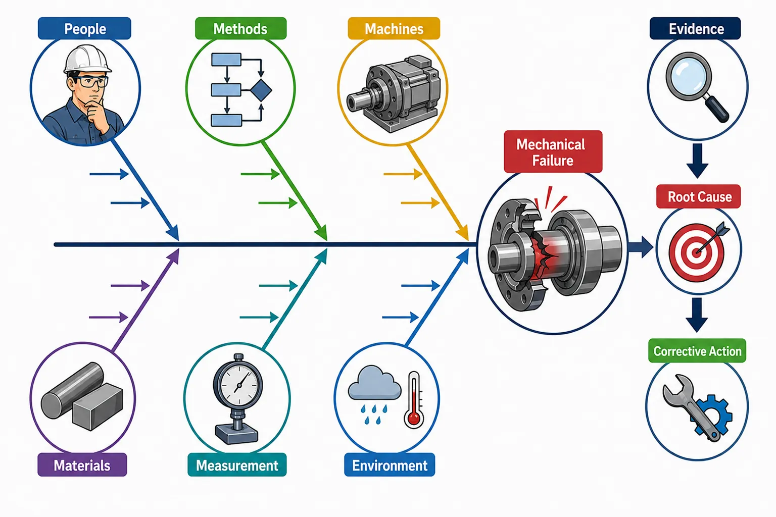
People
Potential causes may include:
- Competence gaps.
- Inadequate training.
- Poor supervision.
- Miscommunication.
- Incorrect interpretation.
- Fatigue.
- Inadequate authorisation.
The investigation should avoid automatically blaming individuals.
The important question is:
Why did the system allow the human error to occur or remain undetected?
Methods
Possible causes include:
- Inadequate procedure.
- Incorrect sequence.
- Missing inspection point.
- Unclear acceptance criteria.
- Poor installation methodology.
- Inadequate maintenance procedure.
- Outdated work instruction.
Machines
Potential causes include:
- Equipment wear.
- Machine misalignment.
- Tool deterioration.
- Calibration problems.
- Equipment capacity limitations.
- Poor maintenance.
- Incorrect machine settings.
Materials
Potential causes include:
- Incorrect material grade.
- Defective material.
- Poor storage.
- Material contamination.
- Incorrect consumables.
- Supplier variation.
- Traceability failure.
Measurement
Potential causes include:
- Incorrect instrument.
- Calibration failure.
- Poor measurement method.
- Operator error.
- Inadequate measurement resolution.
- Environmental influence.
- Incorrect reference point.
Environment
Potential causes include:
- Temperature.
- Humidity.
- Dust.
- Vibration.
- Poor lighting.
- Congestion.
- Weather.
- Contamination.
The Fishbone Diagram does not itself prove which cause is responsible. It generates and organises possible causes that must subsequently be tested using evidence.
Using a Fishbone Diagram Correctly
The process can be structured as:
Define the Failure
Place the clearly defined problem at the end of the diagram.
Identify Major Cause Categories
Select relevant categories.
Brainstorm Potential Causes
Record technically plausible causes.
Investigate Each Cause
Use:
- Measurements.
- Records.
- Interviews.
- Inspections.
- Testing.
- Historical data.
Eliminate Unsupported Causes
Do not retain causes simply because they sound plausible.
Identify Evidence-Supported Causes
Prioritise causes supported by objective evidence.
Confirm the Root Cause
Determine whether removing or controlling the cause should prevent recurrence.
Five Whys as a Supporting Method
The Five Whys technique can be used alongside Fishbone analysis.
Example:
Problem: Repeated pump alignment failure.
Why 1: Why did alignment fail?
Because final shaft alignment exceeded the specified tolerance.
Why 2: Why did alignment exceed tolerance?
Because the installation sequence produced inconsistent results.
Why 3: Why was the sequence inconsistent?
Because teams used different interpretations of the installation method.
Why 4: Why were interpretations different?
Because the work instruction did not clearly define the sequence and verification points.
Why 5: Why was the instruction inadequate?
Because the process-control review did not identify the ambiguity before implementation.
The investigation may therefore identify a process-design weakness rather than simply an operator error.
Combining Fishbone and Five Whys
These tools can work together.
Fishbone Diagram
Broadens the investigation.
↓
Five Whys
Deepens selected causal chains.
↓
Evidence Verification
Tests the proposed causes.
↓
Root Cause
Identifies the cause requiring corrective action.
This combination is particularly useful for complex mechanical failures where several plausible causes exist.
Advanced RCA for Recurring Mechanical Failures
Recurring failures require special attention because previous corrective action has apparently failed to prevent recurrence.
The investigator should examine:
- Previous NCRs.
- Previous RCA reports.
- Previous corrective actions.
- Previous maintenance.
- Equipment history.
- Supplier history.
- Process changes.
- Personnel changes.
- Design revisions.
- Environmental changes.
The key question is:
Why did the previous control fail to prevent recurrence?
This may reveal a second-level systemic cause.
Practical Example: Repeated Pump Vibration
Failure
A centrifugal pump repeatedly develops abnormal vibration after installation.
Initial Correction
The team realigns the pump.
The vibration reduces temporarily.
Recurrence
The vibration returns after operation.
RCA Investigation
The team examines:
- Alignment records.
- Foundation condition.
- Coupling condition.
- Installation procedure.
- Measurement equipment.
- Operating conditions.
- Pipe connection.
- Maintenance history.
Fishbone Categories
People
- Inconsistent installation competence.
Methods
- Alignment sequence not consistently applied.
Machines
- Alignment equipment condition.
Materials
- Coupling component condition.
Measurement
- Measurement method consistency.
Environment
- Operating temperature and vibration.
Evidence
The investigation finds that alignment changes occur after connected piping is tightened.
This identifies a potential interaction between installation sequence and equipment alignment.
Corrective Action
The project revises:
- Installation sequence.
- Alignment verification.
- Piping-interface checks.
- Final acceptance requirements.
Verification
Subsequent equipment installations are monitored.
If vibration remains within specified requirements over an appropriate operating period, the corrective action can be evaluated for effectiveness.
Practical Example: Recurring Weld Cracking
Problem
Repeated cracking is identified in similar welded components.
Possible Causes
- Welding procedure.
- Material properties.
- Preheat.
- Consumables.
- Joint preparation.
- Welder competence.
- Heat input.
- Environmental conditions.
- Inspection method.
Investigation
The team compares:
- Material certificates.
- Welding records.
- Welder records.
- NDT results.
- Repair history.
- Environmental conditions.
The analysis identifies a consistent relationship between cracking and a particular material batch.
Further material investigation is then required before concluding that material characteristics are the root cause.
This demonstrates the importance of correlation and evidence rather than assumptions.
Practical Example: Repeated Mechanical Seal Failure
A rotating machine experiences repeated mechanical seal failures.
Initial actions include:
- Replacing seals.
- Checking leakage.
- Restarting equipment.
The failures continue.
RCA examines:
- Shaft alignment.
- Operating conditions.
- Seal specification.
- Installation method.
- Lubrication.
- Equipment vibration.
- Shaft condition.
- Maintenance procedure.
The investigation may reveal that the selected seal is being exposed to conditions outside its intended operating range.
The corrective action should then address the verified underlying cause rather than repeatedly replacing the seal.
Practical Example: Recurring Dimensional Non-Conformity
A machining operation repeatedly produces components outside tolerance.
The Fishbone investigation considers:
- Machine.
- Tool.
- Material.
- Operator.
- Measurement.
- Method.
- Environment.
Evidence shows that dimensional deviation increases after extended machining cycles.
Further investigation identifies tool wear as a contributing factor.
The improvement may include:
- Tool-condition monitoring.
- Defined replacement criteria.
- Additional in-process measurements.
- Updated work instructions.
The effectiveness can then be monitored through dimensional KPIs.
Case Study: Complex Mechanical Failure
Project Background
A large industrial project experiences repeated failures during mechanical equipment commissioning. Several pumps fail functional testing because of abnormal vibration and temperature.
The equipment has already passed:
- Installation inspection.
- Alignment verification.
- Mechanical completion.
- Initial testing.
Initial Response
The project team replaces several components and repeats alignment.
The equipment passes temporarily but later shows similar symptoms.
RCA Initiation
Because the problem is recurring, management establishes a multidisciplinary investigation team.
Evidence Collection
The team reviews:
- Installation records.
- Alignment measurements.
- Commissioning data.
- Equipment history.
- Maintenance records.
- Manufacturer documentation.
- Operating conditions.
- Field observations.
Fishbone Analysis
Potential causes are grouped under:
- People.
- Methods.
- Machines.
- Materials.
- Measurement.
- Environment.
Investigation
The team discovers that several installations were completed using different sequences for connecting associated mechanical systems.
This creates inconsistent mechanical loading during final alignment.
Root-Cause Assessment
The investigation concludes that the process-control system did not adequately control the installation sequence and final verification of mechanical interfaces.
Corrective Actions
The project:
- Revises the installation procedure.
- Introduces an additional interface verification.
- Standardises alignment sequence.
- Improves competency briefings.
- Strengthens final inspection.
- Adds targeted field surveillance.
Effectiveness Verification
Subsequent installations are monitored using:
- Alignment results.
- Vibration measurements.
- Commissioning performance.
- NCR trends.
The results demonstrate improved consistency.
Lessons Learned
The case demonstrates that:
- Replacing failed components does not necessarily remove the root cause.
- Recurring failures require systemic investigation.
- Multiple disciplines may need to participate.
- Fishbone analysis helps organise possible causes.
- Evidence must be used to confirm causal relationships.
- Corrective actions should address process weaknesses.
- Effectiveness must be verified using subsequent performance.
Corrective Action Versus Preventive Improvement
Corrective action addresses the cause of an identified non-conformity.
Preventive improvement seeks to reduce the likelihood of future problems.
For example:
Corrective action: Repair the defective mechanical component.
Root-cause corrective action: Revise the process that caused the defect.
Preventive improvement: Apply the improved control to similar equipment before a defect occurs.
This distinction is important for continuous improvement.
Verifying the Root Cause
A proposed root cause should satisfy several questions:
- Is it supported by evidence?
- Does it explain the observed failure?
- Is it consistent with historical data?
- Does it explain recurrence?
- Can the cause be controlled?
- Would controlling it reasonably reduce recurrence?
- Are alternative causes adequately considered?
If the proposed cause cannot be supported by evidence, the investigation should continue.
Failure Mode and RCA Integration
RCA can also be linked with Failure Mode and Effects Analysis (FMEA).
FMEA focuses on identifying potential failure modes before or during process development.
RCA generally investigates failures that have already occurred.
The relationship can be understood as:
FMEA → Anticipate Potential Failures
RCA → Investigate Actual Failures
Information from an RCA can then improve future FMEA activities.
Data Sources for Mechanical RCA
A strong investigation may use:
Quality Data
- NCRs.
- Inspection results.
- Audit findings.
- Rework records.
- Test results.
Engineering Data
- Drawings.
- Calculations.
- Specifications.
- Equipment manuals.
- Design revisions.
Manufacturing Data
- Process records.
- Machine settings.
- Tool history.
- Production records.
Installation Data
- Alignment records.
- Torque records.
- Installation checklists.
- Field observations.
Maintenance Data
- Failure history.
- Maintenance activities.
- Component replacement.
- Operating conditions.
Material Data
- Material certificates.
- Test results.
- Batch information.
- Supplier records.
Using Evidence Effectively
Evidence should be:
- Relevant.
- Reliable.
- Traceable.
- Current.
- Consistent.
- Verifiable.
The investigation should avoid:
- Unverified assumptions.
- Unsupported opinions.
- Blame-based conclusions.
- Selective evidence.
- Incomplete records.
A good RCA should allow an independent technical reviewer to understand how the conclusion was reached.
Measuring RCA Effectiveness
RCA effectiveness can be evaluated through KPIs such as:
- Repeat failure rate.
- Repeat NCR rate.
- Rework rate.
- Equipment failure frequency.
- Corrective-action recurrence.
- First-pass acceptance.
- Testing success.
- Maintenance intervention frequency.
The appropriate indicator depends on the failure being investigated.
For example, a welding RCA may use weld repair rate and repeat NCRs.
A rotating-equipment RCA may use:
- Vibration trends.
- Failure frequency.
- Functional test results.
- Maintenance interventions.
Common RCA Mistakes
Mechanical engineering organisations should avoid:
- Treating symptoms as root causes.
- Stopping at the first plausible explanation.
- Blaming individuals prematurely.
- Ignoring management-system factors.
- Failing to collect evidence.
- Using Fishbone diagrams as proof rather than investigation tools.
- Treating Five Whys as a rigid five-question requirement.
- Ignoring previous failures.
- Implementing corrective action without verification.
- Closing RCA actions based only on paperwork.
- Failing to update procedures.
- Ignoring similar equipment.
- Failing to share lessons learned.
Benefits of Advanced Problem-Solving Methodologies
Quality Benefits
- Reduced recurring defects.
- Improved process stability.
- Better corrective actions.
- Stronger prevention.
- Improved mechanical integrity.
Operational Benefits
- Reduced equipment downtime.
- Reduced rework.
- Improved process reliability.
- Better maintenance planning.
- More consistent production.
Financial Benefits
- Reduced repair costs.
- Reduced replacement costs.
- Lower cost of poor quality.
- Reduced production losses.
- Reduced project delays.
Management Benefits
- Better decision-making.
- Evidence-based improvement.
- Improved risk management.
- Stronger lessons learned.
- Better resource allocation.
Workforce Benefits
- Improved problem-solving skills.
- Better technical understanding.
- Increased participation.
- Stronger quality awareness.
- Improved cross-functional collaboration.
Professional RCA Procedure
Phase 1: Identify
- Define the failure.
- Establish scope.
- Determine significance.
- Identify affected equipment.
Phase 2: Contain
- Control immediate risk.
- Protect personnel.
- Isolate affected components.
- Prevent further propagation.
Phase 3: Investigate
- Establish timeline.
- Collect evidence.
- Interview personnel.
- Inspect equipment.
- Review documentation.
Phase 4: Analyse
- Develop Fishbone Diagram.
- Apply Five Whys where appropriate.
- Analyse trends.
- Compare historical data.
- Evaluate alternative causes.
Phase 5: Confirm
- Verify root cause.
- Confirm evidence.
- Challenge assumptions.
- Assess causal relationships.
Phase 6: Correct
- Develop corrective action.
- Assign responsibilities.
- Set completion requirements.
- Update procedures where necessary.
Phase 7: Verify
- Monitor performance.
- Review KPIs.
- Check recurrence.
- Confirm effectiveness.
Phase 8: Standardise
- Update procedures.
- Communicate lessons.
- Train personnel.
- Apply controls to similar processes.
Integrating RCA with Continuous Improvement
RCA should form part of the wider continuous improvement cycle:
Failure → Investigation → Root Cause → Corrective Action → Verification → Standardisation → Monitoring
The process should not stop when the immediate failure has been repaired.
The organisation should ask:
- What else could be affected?
- Where else could the same cause exist?
- Should procedures change?
- Should training change?
- Should inspection frequency change?
- Should supplier controls change?
- Should risk assessments be updated?
This approach transforms an individual failure into an opportunity for organisational learning.
Applying RCA Across Mechanical Engineering Activities
Fabrication
RCA can investigate:
- Weld defects.
- Dimensional failures.
- Distortion.
- Material errors.
- Surface defects.
Machining
RCA can address:
- Dimensional variation.
- Tool failure.
- Surface-finish problems.
- Machine instability.
Assembly
RCA can investigate:
- Incorrect fit.
- Fastener failures.
- Component damage.
- Assembly sequence problems.
Installation
RCA can address:
- Alignment problems.
- Installation damage.
- Incorrect torque.
- Interface failures.
Testing
RCA can investigate:
- Pressure-test failures.
- Leakage.
- Functional failures.
- Repeated commissioning defects.
Maintenance
RCA can address:
- Repeated breakdowns.
- Premature component failure.
- Excessive vibration.
- Lubrication-related problems.
Advanced Professional Judgement
At Level 6, RCA requires the ability to distinguish correlation from causation.
For example, if two events occur at the same time, that does not automatically prove that one caused the other.
A professional investigation should ask:
- Is there a technical mechanism linking them?
- Is there supporting evidence?
- Does the pattern occur repeatedly?
- Are alternative causes possible?
- Can testing confirm the relationship?
- Does controlling the suspected cause improve performance?
This prevents premature conclusions.
Key Takeaways
Advanced problem-solving in mechanical engineering should:
- Define failures precisely.
- Control immediate risks.
- Preserve evidence.
- Establish failure timelines.
- Use multidisciplinary investigation teams.
- Distinguish symptoms from causes.
- Use Fishbone diagrams to structure possible causes.
- Use Five Whys to investigate causal chains.
- Verify proposed causes using evidence.
- Consider technical and systemic factors.
- Avoid premature blame.
- Examine recurring failures for common causes.
- Implement corrective actions addressing verified causes.
- Measure corrective-action effectiveness.
- Standardise successful improvements.
- Share lessons learned.
- Apply findings to similar equipment and processes.
Conclusion
Root Cause Analysis and Fishbone diagrams provide powerful methodologies for solving complex and recurring mechanical failures because they encourage engineers and QA/QC professionals to move beyond immediate symptoms and investigate the conditions that allowed failures to occur. A technically effective RCA should combine clear problem definition, containment, evidence collection, failure-timeline development, structured cause identification, objective verification, corrective action, and effectiveness monitoring. Fishbone diagrams help organise potential causes across people, methods, machines, materials, measurement, and environmental factors, while techniques such as Five Whys can help investigate deeper causal relationships.
For Level 6 mechanical engineering and QA/QC professionals, the most important principle is that a successful RCA is not measured by how quickly a report is completed or an NCR is closed. It is measured by whether the organisation understands the true causes of failure and can demonstrate that corrective action has reduced the likelihood of recurrence. When RCA findings are integrated into continuous improvement, risk management, procedures, training, inspection plans, maintenance strategies, supplier controls, and performance monitoring, individual failures become opportunities for organisational learning. This evidence-based approach can reduce recurring mechanical defects, improve equipment reliability, minimise rework and downtime, strengthen quality assurance processes, and enhance the long-term performance of mechanical engineering operations.
3: Design and Execute a Structured Continuous Improvement Initiative to Eliminate Process Waste, Reduce Rework Rates, and Optimise Mechanical Assembly Operations
A structured continuous improvement initiative provides a systematic method for improving mechanical assembly operations by identifying process waste, analysing the causes of rework, improving workflow, standardising effective practices, and monitoring performance over time. Mechanical assembly involves the integration of multiple components, fasteners, seals, shafts, couplings, bearings, housings, piping interfaces, supports, and other mechanical elements. The quality of the final assembly depends not only on the quality of individual components but also on the sequence, accuracy, tools, inspection controls, personnel competence, material handling, documentation, and environmental conditions used during assembly. A weakness at any stage can generate defects that are expensive to discover and correct later.
Continuous improvement therefore requires more than simply instructing personnel to “work more efficiently”. An effective initiative begins with evidence. Rework records, NCRs, first-pass acceptance data, assembly cycle times, inspection results, material movement, equipment downtime, waiting periods, tool availability, and field observations should be examined to determine where performance is being lost. Lean principles can then be used to identify waste, Six Sigma techniques can be applied where variation and defect patterns require deeper analysis, and PDCA or DMAIC can provide a structured improvement framework. The objective is to improve quality and efficiency simultaneously rather than reducing cost or time at the expense of mechanical integrity.
For a Level 6 mechanical QA/QC professional, designing and executing such an initiative requires professional judgement, process analysis, risk-based thinking, stakeholder coordination, and evidence-based decision-making. The initiative should establish a clear baseline, identify measurable objectives, determine root causes, develop improvement actions, implement controlled changes, verify results, and standardise successful practices. When effectively managed, continuous improvement can reduce unnecessary movement, waiting, excess processing, defects, material waste, and repeated assembly work while improving first-pass acceptance, productivity, traceability, process consistency, and overall mechanical engineering performance.
Understanding Continuous Improvement in Mechanical Assembly
Mechanical assembly is a process in which individual components are brought together to create a functional system or completed mechanical product. The process may range from relatively simple assemblies to complex industrial equipment involving numerous components and tightly controlled interfaces.
Typical assembly activities may include:
- Component identification.
- Material verification.
- Cleaning and preparation.
- Positioning.
- Alignment.
- Fastener installation.
- Torque application.
- Seal installation.
- Bearing installation.
- Coupling installation.
- Dimensional verification.
- Functional checks.
- Final inspection.
- Testing.
- Documentation.
Every activity consumes resources. Some activities directly contribute to the required product, while others may consume time and resources because of inefficiencies, defects, waiting, or inadequate planning.
Continuous improvement aims to distinguish between necessary work and avoidable process waste while protecting all technical and quality requirements.
Key Definitions and Concepts
| Concept | Definition | Mechanical Assembly Application |
|---|---|---|
| Continuous Improvement | Systematic and ongoing enhancement of process performance | Improving assembly quality, efficiency and consistency |
| Process Waste | Activity consuming resources without providing required value | Excess movement, waiting, repeated work or unnecessary handling |
| Rework | Work performed again to correct a defect or non-conformity | Re-aligning, dismantling or replacing incorrectly installed components |
| First-Pass Acceptance | Percentage of work accepted without correction | Assembly accepted without rework or repeat inspection |
| Process Mapping | Visual representation of process steps and interactions | Mapping component receipt through final assembly |
| Standard Work | Defined and controlled method for performing an activity | Standardised assembly and inspection sequence |
| Cycle Time | Time required to complete a defined process | Time required to assemble a mechanical unit |
| Value-Added Activity | Activity contributing directly to required output | Correct component installation and controlled assembly |
| Non-Value-Added Activity | Activity consuming resources without required value | Searching for tools or unnecessary movement |
| Root Cause | Fundamental cause allowing a problem to occur | Weak assembly procedure or inadequate process control |
| Kaizen | Continuous incremental improvement approach | Small team-led improvements to assembly processes |
| PDCA | Plan, Do, Check, Act improvement cycle | Structured implementation and verification |
| DMAIC | Define, Measure, Analyse, Improve, Control methodology | Data-driven improvement of recurring assembly problems |
| Standardisation | Establishing an approved consistent method | Applying one controlled assembly sequence |
| Process Capability | Ability of a stable process to meet requirements | Consistently achieving assembly tolerances |
Why Mechanical Assembly Requires Continuous Improvement
Assembly processes can contain hidden inefficiencies even when the final product appears acceptable.
For example, an assembly team may consistently meet technical requirements but spend significant time:
- Searching for tools.
- Waiting for components.
- Waiting for inspection.
- Repeating measurements.
- Moving components between work areas.
- Correcting avoidable alignment errors.
- Locating drawings.
- Obtaining missing documentation.
These activities may not immediately generate an NCR, but they can reduce productivity and increase project costs.
Similarly, repeated rework may indicate that the process is producing an acceptable final product only after several correction cycles.
A mature QA/QC system should therefore examine both:
Product conformity
and
Process effectiveness
Identifying Process Waste
Waste should be identified using direct observation, process mapping, quality records, employee feedback, and performance data.
Common waste categories include:
- Defects.
- Overproduction.
- Waiting.
- Transportation.
- Excess processing.
- Inventory.
- Unnecessary motion.
- Underused human capability.
Defects and Rework
Defects are among the most significant forms of waste because they can generate multiple additional activities.
A single incorrect assembly may require:
Inspection → Defect identification → Investigation → Dismantling → Correction → Reassembly → Reinspection → Documentation
This can consume substantially more resources than correct first-time assembly.
Examples include:
- Incorrect component orientation.
- Incorrect torque.
- Damaged seals.
- Misalignment.
- Incorrect fasteners.
- Incorrect component identification.
- Assembly sequence errors.
Waiting
Waiting occurs when personnel or processes cannot proceed because another requirement has not been completed.
Examples include:
- Waiting for inspection release.
- Waiting for materials.
- Waiting for drawings.
- Waiting for calibrated equipment.
- Waiting for engineering clarification.
- Waiting for supervisor approval.
Waiting should not automatically be eliminated. Some inspection and approval stages are necessary quality controls.
The objective is to eliminate avoidable waiting while preserving required controls.
Unnecessary Transportation
Components may be moved repeatedly between:
- Storage.
- Preparation.
- Assembly.
- Inspection.
- Testing.
- Rework areas.
Excessive movement can increase:
- Handling time.
- Damage risk.
- Identification risk.
- Labour consumption.
- Workflow congestion.
Excess Processing
Excess processing occurs when work is performed beyond what is necessary to satisfy defined requirements.
Examples may include:
- Duplicate documentation.
- Repeated measurements without technical justification.
- Unnecessary handling.
- Repeating inspections caused by poor process planning.
The professional must distinguish unnecessary processing from mandatory quality verification.
Inventory and Work-in-Progress
Excess work-in-progress can conceal process problems.
Large quantities of partially assembled equipment may create:
- Space constraints.
- Identification difficulties.
- Increased handling.
- Storage damage.
- Delayed defect detection.
A balanced inventory approach is therefore required.
Unnecessary Motion
Workers may spend substantial time:
- Searching for tools.
- Walking to inspection areas.
- Locating components.
- Finding documents.
- Retrieving measuring equipment.
Workshop layout and point-of-use organisation can reduce such waste.
Underused Human Capability
Experienced assemblers, inspectors, technicians, and supervisors often have valuable process knowledge.
An improvement initiative should provide mechanisms for personnel to identify:
- Repeated problems.
- Inefficient sequences.
- Tool difficulties.
- Documentation weaknesses.
- Safety-quality interactions.
- Practical improvement opportunities.
Establishing a Baseline
Before implementing improvements, the organisation needs to understand current performance.
Relevant baseline indicators may include:
- Rework rate.
- First-pass acceptance.
- Assembly cycle time.
- NCR frequency.
- Inspection rejection.
- Defect frequency.
- Waiting time.
- Equipment downtime.
- Material movement.
- Tool-related delays.
For example:
If 100 assemblies are completed and 18 require rework, the rework rate is 18%.
This baseline can then be compared with subsequent performance.
Selecting Improvement Objectives
Objectives should be specific and measurable.
Examples include:
- Reduce assembly rework.
- Improve first-pass acceptance.
- Reduce avoidable waiting.
- Reduce unnecessary movement.
- Improve tool availability.
- Reduce repeated inspection failures.
- Improve assembly cycle time.
- Improve documentation accuracy.
A suitable objective might be:
“Reduce mechanical assembly rework from the established baseline while maintaining specified acceptance requirements.”
Designing the Improvement Initiative
A structured initiative should include:
- Problem definition.
- Baseline measurement.
- Process mapping.
- Waste identification.
- Root-cause analysis.
- Improvement design.
- Risk assessment.
- Controlled implementation.
- Performance monitoring.
- Effectiveness verification.
- Standardisation.
- Continual monitoring.
Step 1: Define the Problem
A strong problem statement should identify:
- What is happening?
- Where is it happening?
- How frequently?
- What is the impact?
- Which processes are affected?
- What evidence demonstrates the problem?
Weak statement:
“Assembly is inefficient.”
Stronger statement:
“Mechanical assembly activities are experiencing repeated alignment rework and extended inspection waiting, resulting in reduced first-pass acceptance and increased cycle time.”
Step 2: Map the Existing Process
A process map should show the actual sequence rather than the theoretical sequence.
Example:
Material Receipt
↓
Identification
↓
Component Preparation
↓
Assembly
↓
Alignment
↓
Fastening
↓
Inspection
↓
Testing
↓
Final Acceptance
The evaluator should identify where delays, loops, defects, and unnecessary movement occur.
Step 3: Observe Actual Work
Direct observation is essential.
The QA/QC professional should examine:
- How workers actually perform the task.
- Whether the approved sequence is followed.
- Where workers wait.
- Where components move.
- Where errors occur.
- Where inspection is repeated.
- Where documentation delays progress.
This may reveal differences between the documented process and actual practice.
Step 4: Analyse Rework
Rework should be categorised rather than treated as one overall figure.
Categories may include:
- Alignment.
- Torque.
- Component identification.
- Seal installation.
- Dimensional errors.
- Fastener problems.
- Assembly sequence.
- Documentation.
- Inspection failures.
A Pareto analysis can identify which categories contribute most significantly to total rework.
Step 5: Identify Root Causes
For significant recurring problems, use:
- Fishbone diagrams.
- Five Whys.
- Process analysis.
- Trend analysis.
- Direct field observation.
Possible root causes include:
- Poor procedure.
- Inadequate training.
- Incorrect tools.
- Poor layout.
- Weak inspection timing.
- Inadequate material control.
- Measurement problems.
- Communication gaps.
Step 6: Develop Improvement Solutions
Improvement solutions should address verified causes.
Potential actions include:
- Reorganising workstations.
- Introducing point-of-use tools.
- Revising work instructions.
- Improving material identification.
- Standardising assembly sequences.
- Introducing visual controls.
- Improving inspection planning.
- Providing targeted training.
- Improving tool management.
- Establishing in-process verification.
Step 7: Assess Risks Before Implementation
Process changes can create new risks.
Before implementing a change, consider:
- Mechanical integrity.
- Inspection effectiveness.
- Personnel competence.
- Equipment limitations.
- Traceability.
- Documentation.
- Safety.
- Customer requirements.
A process should never be accelerated by removing a mandatory inspection or technical control simply because that activity appears to create waiting.
Step 8: Pilot the Improvement
Where practical, implement the change on a controlled basis.
A pilot may involve:
- One assembly line.
- One equipment type.
- One work team.
- One production batch.
- One installation area.
The pilot provides evidence before wider implementation.
Step 9: Measure the Results
Compare post-improvement results with the baseline.
Useful measures include:
- Rework rate.
- First-pass acceptance.
- Cycle time.
- NCR rate.
- Inspection rejection.
- Waiting time.
- Material movement.
- Tool-related delays.
Step 10: Verify Quality Has Not Been Compromised
Improvement must achieve a balanced result.
For example:
If assembly cycle time decreases by 20% but defects increase by 15%, the initiative cannot be considered successful.
The professional should evaluate:
Quality + Efficiency + Reliability + Compliance
rather than efficiency alone.
Step 11: Standardise Successful Improvements
Once an improvement is verified, it should be incorporated into controlled systems.
This may involve:
- Updating SOPs.
- Revising work instructions.
- Updating ITPs where applicable.
- Revising checklists.
- Training personnel.
- Updating process maps.
- Establishing new KPIs.
- Communicating lessons learned.
Step 12: Continue Monitoring
An improvement is not complete when the new procedure is issued.
Performance should continue to be monitored to determine whether the improvement is sustained.
Practical Example: Reducing Assembly Rework
Initial Situation
A mechanical assembly workshop reports an 18% rework rate.
The main rework categories are:
- Alignment.
- Fastener torque.
- Seal installation.
- Component orientation.
Investigation
The team performs:
- Process mapping.
- Direct observation.
- Rework analysis.
- Personnel interviews.
- Fishbone analysis.
Findings
The investigation identifies:
- Different assembly sequences between teams.
- Tools stored away from workstations.
- Inconsistent interpretation of the work instruction.
- Inspection performed too late.
- Limited in-process verification.
Improvement Actions
The project:
- Standardises assembly sequence.
- Introduces point-of-use tooling.
- Clarifies work instructions.
- Adds in-process checks.
- Provides targeted team briefings.
Measurement
Following implementation, the project monitors:
- Rework rate.
- First-pass acceptance.
- Assembly time.
- Inspection rejection.
The improvement is considered effective only if quality performance remains compliant while rework and avoidable delays decrease.
Practical Example: Reducing Waiting Time
A mechanical assembly operation has significant delays because inspection personnel are not always available when an assembly stage is completed.
The team maps the process and finds that inspection requests are communicated late.
Improvement actions include:
- Better inspection planning.
- Defined notification points.
- Improved work scheduling.
- Clear communication responsibilities.
- Better coordination between assembly and QA/QC.
The objective is not to remove inspection.
The objective is to improve the timing and coordination of required inspection.
Practical Example: Improving Tool Availability
Assemblers frequently leave their workstations to locate torque tools and measuring equipment.
The improvement team:
- Records tool-search time.
- Maps tool locations.
- Identifies frequently used equipment.
- Introduces point-of-use storage.
- Establishes tool identification.
- Verifies calibration status.
The result can be reduced motion and waiting without changing technical requirements.
Practical Example: Reducing Alignment Rework
A mechanical assembly operation experiences repeated alignment failures.
The team identifies:
- Different alignment methods.
- Inconsistent measurement points.
- Inadequate intermediate verification.
- Variation in personnel practices.
The improvement initiative establishes:
- One standard alignment sequence.
- Defined measurement points.
- Intermediate verification.
- Competency briefing.
- Final acceptance criteria.
Subsequent alignment performance is monitored through first-pass acceptance and rework data.
Case Study: Continuous Improvement of a Mechanical Assembly Line
Project Background
A large engineering facility assembles industrial mechanical equipment. Management observes that assembly output is below planned capacity despite having sufficient personnel and equipment.
Quality records show:
- High rework.
- Frequent inspection rejection.
- Extended cycle times.
- Excess material movement.
- Repeated waiting for tools and documentation.
Baseline Assessment
The improvement team reviews:
- NCR records.
- Rework records.
- Assembly times.
- Inspection data.
- Field observations.
- Employee feedback.
Process Mapping
The existing process reveals multiple loops between:
- Assembly.
- Inspection.
- Rework.
- Reinspection.
The team determines that several defects are being discovered late.
Waste Analysis
The principal waste categories are:
- Defects.
- Waiting.
- Motion.
- Transportation.
- Excess processing.
Root-Cause Analysis
A Fishbone diagram identifies possible causes involving:
- People.
- Methods.
- Machines.
- Materials.
- Measurement.
- Environment.
Further evidence shows that inconsistent assembly sequencing is a significant contributor.
Improvement Design
The project develops:
- Standard work instructions.
- Point-of-use tooling.
- Improved component identification.
- Earlier in-process checks.
- Revised workflow.
- Targeted personnel training.
Pilot Implementation
The revised approach is implemented on one assembly team.
Performance is compared with the baseline.
Results
The team observes:
- Lower rework.
- Better first-pass acceptance.
- Reduced unnecessary movement.
- Shorter avoidable waiting.
- Improved inspection coordination.
Standardisation
Following verification, the improved process is implemented across similar assembly activities.
Lessons Learned
The case demonstrates that successful continuous improvement requires more than introducing a new checklist. It requires:
- Evidence.
- Process understanding.
- Root-cause analysis.
- Workforce involvement.
- Controlled implementation.
- Measurement.
- Standardisation.
Applying PDCA
PDCA is particularly suitable for structured incremental improvement.
Plan
- Identify the problem.
- Establish baseline.
- Determine causes.
- Develop improvement.
Do
- Implement the improvement.
- Control the trial.
- Record results.
Check
- Compare results with baseline.
- Assess quality.
- Review KPIs.
Act
- Standardise the improvement.
- Revise procedures.
- Train personnel.
- Continue monitoring.
Applying DMAIC
For more complex data-driven problems, DMAIC may be appropriate.
Define
Clearly establish the assembly problem.
Measure
Collect reliable performance data.
Analyse
Identify verified causes.
Improve
Implement targeted solutions.
Control
Monitor the improved process and prevent regression.
Selecting KPIs
KPIs should directly reflect the improvement objective.
| KPI | Purpose | Example Application |
|---|---|---|
| Rework Rate | Measures work requiring correction | Assembly defects |
| First-Pass Acceptance | Measures work accepted initially | Final assembly |
| NCR Rate | Tracks non-conformities | Mechanical components |
| Cycle Time | Measures process duration | Assembly operations |
| Waiting Time | Identifies process delays | Inspection coordination |
| Defect Rate | Measures output defects | Component assembly |
| Inspection Rejection | Measures failed inspections | Alignment or torque checks |
| Tool Delay | Measures tool-related waiting | Assembly workstation |
| Repeat Failure Rate | Measures recurrence | Mechanical equipment |
| Process Compliance | Measures adherence to approved methods | Assembly sequence |
Balancing Quality, Cost, and Time
Continuous improvement should balance competing priorities.
A successful initiative should consider:
Quality
- Conformity.
- Mechanical integrity.
- Reliability.
- Inspection effectiveness.
Cost
- Labour.
- Material.
- Rework.
- Equipment.
- Waste.
Time
- Cycle time.
- Waiting.
- Schedule.
- Inspection coordination.
Risk
- Failure consequences.
- Process changes.
- Competence.
- Technical controls.
Improving one factor while damaging another is not sustainable improvement.
Workforce Involvement
Personnel should be actively involved because they understand operational realities.
Improvement teams can obtain information through:
- Toolbox discussions.
- Team meetings.
- Structured interviews.
- Improvement workshops.
- Suggestion systems.
- Direct observation.
However, employee suggestions should still be evaluated against technical requirements and objective evidence.
Role of QA/QC Professionals
The QA/QC professional should:
- Analyse quality data.
- Identify improvement opportunities.
- Facilitate root-cause analysis.
- Verify process compliance.
- Assess risks.
- Establish quality KPIs.
- Monitor improvement results.
- Verify corrective actions.
- Support standardisation.
- Communicate lessons learned.
The QA/QC role should not be limited to final inspection.
Role of Mechanical Engineering Teams
Mechanical engineers may contribute through:
- Technical analysis.
- Design review.
- Equipment assessment.
- Process optimisation.
- Failure analysis.
- Specification review.
Role of Supervisors
Supervisors support implementation by:
- Communicating requirements.
- Monitoring work.
- Supporting personnel.
- Identifying practical problems.
- Enforcing standardised processes.
- Reporting deviations.
Role of Management
Management should provide:
- Resources.
- Time.
- Leadership.
- Training.
- Appropriate equipment.
- Performance monitoring.
- Support for improvement culture.
Without management support, continuous improvement can become an isolated QA/QC activity.
Common Challenges
Continuous improvement initiatives may encounter:
- Resistance to change.
- Poor data quality.
- Limited resources.
- Inadequate training.
- Production pressure.
- Weak management support.
- Poor communication.
- Unclear responsibilities.
- Inconsistent implementation.
These challenges should be identified during initiative planning.
Avoiding Unintended Consequences
A change intended to reduce waste may create new problems.
For example:
Reducing inventory too aggressively may cause material shortages.
Reducing inspection frequency may increase defect escape.
Increasing assembly speed may increase human error.
Reducing documentation may weaken traceability.
Therefore, every improvement should be evaluated for its broader consequences.
Sustainability of Improvement
An improvement should be sustained through:
- Controlled procedures.
- Training.
- Competency verification.
- KPIs.
- Audits.
- Field evaluations.
- Management review.
- Lessons learned.
The objective is to prevent the organisation from gradually returning to the previous method.
Professional Evaluation of Initiative Effectiveness
A Level 6 professional should ask:
- Was the original problem correctly defined?
- Was baseline data reliable?
- Were root causes properly investigated?
- Were improvement actions linked to verified causes?
- Were risks assessed?
- Was the change implemented consistently?
- Did quality remain compliant?
- Did rework decrease?
- Did waste decrease?
- Did process performance improve?
- Was improvement sustained?
- Were procedures updated?
- Were lessons transferred to similar processes?
Key Benefits
Quality Improvement
- Lower defect rates.
- Reduced NCRs.
- Improved first-pass acceptance.
- Better process consistency.
- Improved mechanical integrity.
Efficiency Improvement
- Reduced waiting.
- Less unnecessary movement.
- Better workflow.
- Improved resource utilisation.
- Shorter avoidable cycle time.
Cost Improvement
- Reduced rework.
- Lower material waste.
- Reduced labour losses.
- Lower inspection repetition.
- Reduced cost of poor quality.
Project Improvement
- Better schedule performance.
- Improved predictability.
- Reduced quality-related delays.
- Improved commissioning readiness.
Organisational Improvement
- Stronger quality culture.
- Better employee participation.
- Improved problem-solving.
- Better use of quality data.
- Stronger continual improvement capability.
Key Takeaways
A structured continuous improvement initiative for mechanical assembly should:
- Define the operational problem clearly.
- Establish reliable baseline data.
- Map the actual process.
- Identify value and non-value activities.
- Analyse waste categories.
- Analyse rework by defect type.
- Identify root causes.
- Develop measurable objectives.
- Involve relevant personnel.
- Assess risks before changing processes.
- Pilot improvements where appropriate.
- Measure post-improvement performance.
- Protect technical quality requirements.
- Verify effectiveness.
- Standardise successful improvements.
- Monitor performance continuously.
- Capture lessons learned.
Conclusion
Designing and executing a structured continuous improvement initiative requires a systematic combination of process analysis, quality management, root-cause investigation, waste reduction, performance measurement, and controlled implementation. In mechanical assembly operations, the objective is not simply to make work faster but to create a process that consistently delivers conforming assemblies with minimum avoidable waste, rework, waiting, unnecessary movement, and resource consumption. By establishing a reliable baseline, mapping actual workflows, analysing rework and process waste, identifying verified root causes, and selecting appropriate improvement methods such as Lean, PDCA, or DMAIC, mechanical engineering organisations can make improvements based on evidence rather than assumptions.
The long-term effectiveness of a continuous improvement initiative depends on verification and standardisation. Improvements should be measured against relevant KPIs such as rework rate, first-pass acceptance, NCR frequency, cycle time, inspection rejection, waiting time, and repeat failure rate. Importantly, improvements in efficiency must never compromise mechanical integrity, inspection requirements, traceability, or defined acceptance criteria. Once an improvement has demonstrated sustainable benefits, it should be incorporated into controlled procedures, work instructions, training, inspection processes, and management monitoring. This creates a continuous improvement cycle in which mechanical assembly operations become more consistent, reliable, efficient, and quality-focused while reducing the cost of poor quality and strengthening overall engineering performance.
4: Establish a System for Gathering and Evaluating Worker Feedback to Build a Sustainable Culture of Ongoing Quality Improvement Within Mechanical Teams
Worker feedback is a valuable source of operational knowledge within mechanical engineering environments because personnel performing manufacturing, fabrication, assembly, installation, inspection, maintenance, and testing activities often encounter process weaknesses before those weaknesses become visible through formal quality records. A sustainable continuous improvement culture therefore requires more than procedures, audits, inspections, and management reviews. It requires a structured mechanism through which workers can report recurring problems, identify inefficient processes, suggest improvements, highlight unclear instructions, and communicate practical barriers affecting quality. When worker feedback is systematically gathered, objectively evaluated, acted upon, and monitored, it can become an important input to mechanical QA/QC management and continuous improvement.
A well-designed feedback system should create a clear connection between what workers experience at the point of work and the organisation’s quality decision-making processes. Feedback may relate to assembly sequences, tooling, material identification, documentation, inspection arrangements, work instructions, equipment condition, training, communication, supplier materials, workplace layout, or recurring defects. However, collecting suggestions alone does not create a quality culture. The organisation must establish a controlled process for receiving, screening, prioritising, investigating, implementing, and closing feedback. Workers should be able to see that useful suggestions receive appropriate consideration and that valid improvement actions result in measurable changes. This creates trust and encourages continued participation.
For Level 6 mechanical QA/QC professionals, worker feedback should be treated as structured operational evidence rather than informal opinion. Feedback can be compared with NCRs, inspection findings, rework data, process KPIs, field observations, audit results, maintenance records, and customer requirements. When multiple sources identify the same weakness, the organisation has stronger evidence for improvement. The ultimate objective is to develop a culture in which quality improvement becomes part of normal mechanical team behaviour, where personnel feel responsible for identifying problems, managers respond constructively, and successful improvements are standardised and sustained.
Understanding Worker Feedback in Mechanical QA/QC
Worker feedback is information provided by personnel about the actual performance, difficulties, risks, weaknesses, and improvement opportunities associated with their work.
In mechanical operations, feedback can originate from:
- Mechanical engineers.
- QA/QC inspectors.
- Fabricators.
- Welders.
- Machinists.
- Assembly technicians.
- Installation teams.
- Maintenance technicians.
- Supervisors.
- Testing personnel.
- Material-control personnel.
- Subcontractor personnel.
The feedback may be positive, negative, corrective, preventive, technical, procedural, or operational.
The key principle is that feedback should be converted into useful organisational knowledge.
Key Definitions and Concepts
| Concept | Definition | Mechanical Engineering Application |
|---|---|---|
| Worker Feedback | Information provided by personnel about work processes and conditions | Identifying recurring assembly or fabrication problems |
| Continuous Improvement | Ongoing systematic enhancement of process performance | Improving mechanical quality and operational efficiency |
| Quality Culture | Shared organisational attitudes and behaviours supporting quality | Encouraging personnel to prevent and report quality problems |
| Suggestion System | Structured mechanism for submitting improvement ideas | Capturing workforce improvement proposals |
| Feedback Channel | Method through which feedback is submitted | Digital forms, meetings, reporting systems or direct communication |
| Psychological Safety | Environment where personnel can raise concerns without inappropriate fear | Encouraging reporting of quality issues |
| Evaluation | Systematic assessment of feedback | Determining technical relevance and priority |
| Root Cause | Fundamental cause of a problem | Investigating recurring quality issues |
| Corrective Action | Action addressing the cause of a detected problem | Removing causes of recurring defects |
| Preventive Improvement | Action reducing the likelihood of future problems | Applying lessons to similar assembly processes |
| Escalation | Raising an issue to an appropriate management level | Escalating critical mechanical quality concerns |
| Feedback Loop | Process connecting feedback, action, and response | Showing workers how suggestions resulted in improvements |
| Recognition | Acknowledgement of useful contribution | Encouraging continued workforce participation |
| Standardisation | Embedding successful improvements into controlled processes | Updating procedures and work instructions |
Why Worker Feedback Matters
Formal QA/QC systems may identify problems through:
- Inspection.
- Testing.
- NCRs.
- Audits.
- Customer complaints.
- KPI trends.
However, these systems may not capture every operational difficulty.
A worker may recognise that:
- A tool is repeatedly unavailable.
- A work instruction is difficult to interpret.
- A material identification system causes confusion.
- An inspection point occurs too late.
- A component is repeatedly damaged during handling.
- A drawing is difficult to use at the work location.
- A particular assembly sequence creates unnecessary rework.
These observations can provide early warning before formal quality failures occur.
Worker Feedback as a Leading Quality Input
Worker feedback can act as a leading source of quality information.
For example:
Worker reports repeated tool-access problems
↓
Management investigates
↓
Tool availability improved
↓
Assembly delays reduced
↓
Potential rework risk reduced
This demonstrates how feedback can prevent problems rather than simply reacting to completed defects.
Building a Feedback System


A sustainable system should include:
- Clear purpose.
- Defined feedback channels.
- Simple submission process.
- Classification criteria.
- Screening and evaluation.
- Risk-based prioritisation.
- Investigation.
- Action assignment.
- Implementation.
- Effectiveness verification.
- Feedback to workers.
- Record retention.
- Trend analysis.
- Management review.
The system should be simple enough for workers to use but structured enough to produce useful evidence.
Establishing Clear Objectives
The organisation should define why worker feedback is being collected.
Objectives may include:
- Identifying quality problems.
- Identifying process waste.
- Reducing rework.
- Improving procedures.
- Improving inspection processes.
- Identifying training needs.
- Improving material control.
- Improving tool availability.
- Identifying recurring defects.
- Strengthening communication.
A clear purpose prevents the feedback system from becoming a general complaints mechanism with no connection to quality improvement.
Creating Multiple Feedback Channels
Different personnel may prefer different methods.
Useful channels include:
Toolbox Meetings
Short structured meetings can allow workers to raise:
- Process problems.
- Quality concerns.
- Material issues.
- Equipment problems.
- Improvement suggestions.
Team Improvement Meetings
These can provide deeper discussion of recurring issues.
Digital Feedback Forms
Digital systems can provide:
- Consistent data.
- Automatic tracking.
- Categorisation.
- Status monitoring.
- Trend analysis.
Paper-Based Suggestions
These can be useful where digital access is limited.
Supervisor Discussions
Supervisors can provide an immediate communication route for operational concerns.
QA/QC Interviews
Quality personnel can directly ask workers about process difficulties during field evaluations.
Designing an Effective Feedback Form
A feedback form should capture sufficient information without becoming unnecessarily complicated.
Useful fields include:
- Date.
- Work area.
- Activity.
- Description.
- Problem observed.
- Suggested improvement.
- Potential consequence.
- Supporting evidence.
- Person or team affected.
Where appropriate, feedback can be submitted anonymously, particularly for sensitive organisational issues.
Example Feedback Structure
Work Area: Mechanical Assembly
Activity: Coupling Installation
Observation: Repeated difficulty accessing torque equipment.
Potential Effect: Increased waiting and risk of inconsistent torque application.
Suggested Improvement: Provide calibrated torque tools at point of use.
This is much more useful than:
“Tools are a problem.”
Encouraging Meaningful Feedback
Workers are more likely to provide useful feedback when:
- Management listens.
- Suggestions are taken seriously.
- Reporting is simple.
- Feedback is acknowledged.
- Improvements are visible.
- Personnel are not unfairly blamed.
- Contributions are recognised.
The organisation should avoid creating a culture where workers believe that reporting a problem means they are responsible for the problem.
Psychological Safety and Quality Reporting
A sustainable improvement culture requires personnel to feel able to report legitimate quality concerns.
For example, an assembler may notice that an installation procedure does not reflect actual site conditions.
If workers believe that raising the issue will result in criticism, they may remain silent.
This can allow:
- Defects.
- Rework.
- Unsafe practices.
- Process deviations.
- Documentation weaknesses
to continue.
A constructive culture treats appropriate reporting as a quality contribution.
Distinguishing Feedback from Complaints
Not every complaint represents a quality improvement opportunity.
The evaluation process should determine whether feedback concerns:
- Technical quality.
- Process effectiveness.
- Resource availability.
- Training.
- Communication.
- Workplace conditions.
- Administrative matters.
Some issues may need to be routed to other organisational functions while still being recorded appropriately.
Feedback Classification
A structured classification system may include:
Quality Issue
Potential or actual failure to meet requirements.
Process Improvement
Opportunity to make a compliant process more efficient.
Technical Concern
Potential engineering or equipment issue.
Documentation Issue
Unclear, outdated, incomplete, or inaccessible information.
Training Need
Evidence that personnel require additional competence development.
Resource Issue
Insufficient tools, equipment, materials, or personnel.
Communication Issue
Information not reaching the appropriate personnel effectively.
Positive Practice
An approach that has produced a beneficial result and may be suitable for standardisation.
Evaluating Feedback
Not every suggestion should be implemented automatically.
Each significant submission should be assessed for:
- Technical validity.
- Quality impact.
- Risk.
- Feasibility.
- Cost.
- Benefit.
- Compliance.
- Resource requirements.
- Potential unintended consequences.
A technically attractive suggestion may be inappropriate if it conflicts with approved engineering requirements.
Risk-Based Prioritisation
Feedback should be prioritised according to consequence and urgency.
High Priority
Examples:
- Potential mechanical integrity issue.
- Critical material traceability problem.
- Repeated equipment failure.
- Significant process deviation.
- Potential defect affecting multiple components.
Medium Priority
Examples:
- Recurring inspection delays.
- Repeated documentation errors.
- Moderate process inefficiency.
Low Priority
Examples:
- Minor workplace organisation improvement.
- Small administrative efficiency.
Prioritisation ensures that critical quality concerns receive timely attention.
Linking Feedback with Existing QA/QC Data
Worker feedback becomes more valuable when compared with existing evidence.
For example:
Worker feedback: “Alignment measurements vary between teams.”
Inspection data: Increased alignment rejection.
NCR data: Repeated alignment non-conformities.
Field observation: Different alignment methods observed.
The combined evidence provides a stronger basis for investigation.
Feedback Evaluation Process
A structured process can follow:
Receive → Screen → Classify → Prioritise → Investigate → Decide → Implement → Verify → Communicate → Record
Each stage should have clear responsibility.
Stage 1: Receive
Capture feedback through approved channels.
Stage 2: Screen
Determine whether the feedback:
- Requires immediate action.
- Requires technical investigation.
- Can be routed elsewhere.
- Is already being addressed.
Stage 3: Classify
Assign the appropriate category.
Stage 4: Prioritise
Consider:
- Quality.
- Risk.
- Frequency.
- Impact.
- Urgency.
Stage 5: Investigate
Use:
- Field observation.
- Data analysis.
- Interviews.
- Root-cause analysis.
- Document review.
- Testing where required.
Stage 6: Decide
Possible outcomes include:
- Implement.
- Investigate further.
- Monitor.
- Reject with technical justification.
- Refer to another department.
Stage 7: Implement
Assign:
- Responsible person.
- Action.
- Deadline.
- Required resources.
Stage 8: Verify
Determine whether the action produced the intended result.
Stage 9: Communicate
Inform workers about:
- Decision.
- Action.
- Reason.
- Outcome.
Stage 10: Record
Maintain appropriate evidence for:
- Trend analysis.
- Management review.
- Lessons learned.
- Audits.
Practical Example: Assembly Tool Feedback
Situation
Several assembly technicians report that calibrated torque tools are stored in a central tool room far from the assembly area.
Initial Feedback
Workers state that tool retrieval causes repeated delays.
Evaluation
The QA/QC team reviews:
- Tool-use records.
- Assembly cycle times.
- Calibration records.
- Worker observations.
- Waiting-time data.
Finding
The tools are correctly calibrated but their location creates unnecessary movement and waiting.
Improvement
The organisation establishes controlled point-of-use storage for frequently used calibrated tools.
Verification
The team monitors:
- Tool retrieval time.
- Assembly cycle time.
- Torque-related NCRs.
If waiting decreases without reducing calibration control or increasing defects, the improvement can be considered effective.
Practical Example: Unclear Work Instruction
Feedback
Assemblers report that a mechanical assembly instruction does not clearly identify the sequence for tightening fasteners.
Evaluation
QA/QC personnel compare:
- Work instruction.
- Engineering requirements.
- Inspection records.
- Actual practice.
Finding
Different teams use different tightening sequences.
Action
The instruction is revised to provide a clearly controlled sequence.
Follow-Up
Personnel are briefed and subsequent inspections are monitored.
Lesson
Worker feedback identified a process-control weakness before it generated larger quality consequences.
Practical Example: Material Identification
Workers report difficulty distinguishing visually similar components.
The organisation investigates:
- Material identification.
- Labelling.
- Storage.
- Drawings.
- Traceability records.
The improvement may involve:
- Better identification labels.
- Improved storage segregation.
- Updated visual controls.
- Revised material-handling instructions.
The change should then be monitored for traceability performance.
Case Study: Building a Sustainable Feedback Culture
Project Background
A mechanical engineering organisation has experienced recurring:
- Assembly defects.
- Rework.
- Inspection delays.
- Material identification issues.
- Documentation errors.
Formal quality systems are in place, but management observes that workers rarely submit improvement suggestions.
Initial Assessment
Management conducts structured discussions with mechanical teams.
Workers report that previous suggestions often received no response.
Cultural Finding
The main weakness is not necessarily lack of ideas.
It is lack of trust in the feedback process.
Improvement Programme
Management establishes:
- Simple feedback forms.
- Weekly improvement reviews.
- Defined response times.
- Risk-based classification.
- Transparent action tracking.
- Worker feedback on outcomes.
- Recognition of useful improvements.
Quality Integration
Feedback is compared with:
- NCRs.
- Rework data.
- Inspection findings.
- KPI trends.
- Field observations.
Results
Several recurring process weaknesses are identified.
Improvement actions include:
- Revised assembly instructions.
- Better tool management.
- Improved material identification.
- Earlier inspection coordination.
Cultural Outcome
Workers begin contributing more frequently because they can see that their observations lead to measurable improvements.
Creating a Closed Feedback Loop
A feedback system should not end when a suggestion is submitted.
A complete loop is:
Worker Observation
↓
Feedback Submission
↓
Evaluation
↓
Action
↓
Verification
↓
Communication
↓
Worker Sees Result
↓
Further Feedback
This closed-loop approach creates trust.
Measuring Feedback-System Performance
The organisation should monitor the feedback process itself.
Potential KPIs include:
- Number of submissions.
- Percentage evaluated.
- Response time.
- Percentage implemented.
- Action closure rate.
- Repeat issue rate.
- Improvement effectiveness.
- Worker participation rate.
However, the number of suggestions alone should not be treated as the primary measure of quality culture.
A high number of submissions may indicate:
- Strong engagement.
But it could also indicate:
- Poor process control.
Context is therefore important.
Measuring Quality Improvement from Feedback
More meaningful indicators may include:
- Reduction in recurring NCRs.
- Reduction in rework.
- Improved first-pass acceptance.
- Reduced inspection rejection.
- Reduced process delays.
- Improved traceability.
- Reduced repeat failures.
The organisation should connect feedback to measurable outcomes where practical.
Management Review of Feedback
Management should periodically review:
- Major feedback themes.
- Recurring issues.
- Improvement actions.
- Unresolved concerns.
- Response times.
- Effectiveness results.
- Resource requirements.
This can help identify systemic issues.
For example, if feedback repeatedly concerns unclear work instructions across several departments, management may need to review document-control and procedure-development processes.
Trend Analysis
Feedback should be analysed over time.
Categories can reveal patterns such as:
- Increasing tool-related concerns.
- Repeated material issues.
- Frequent documentation problems.
- Recurring assembly difficulties.
- Increasing training requests.
Trend analysis helps management move from individual suggestions to systemic improvement.
Using Pareto Analysis
A Pareto approach can identify the most common feedback categories.
For example:
- Tool availability: 30%.
- Documentation: 25%.
- Material handling: 20%.
- Inspection coordination: 15%.
- Training: 10%.
Management can then focus improvement resources on the most significant categories while still considering risk.
Integrating Worker Feedback with RCA
Worker feedback can be an important input to Root Cause Analysis.
For example:
Feedback: “The same component is repeatedly difficult to fit.”
↓
Inspection Data: Increased dimensional rejection.
↓
Field Observation: Installation requires repeated adjustment.
↓
RCA: Common dimensional control weakness identified.
↓
Corrective Action: Process and inspection control improved.
This demonstrates how informal operational knowledge can become objective quality improvement evidence.
Integrating Feedback with Lean
Worker feedback can identify Lean waste such as:
- Waiting.
- Movement.
- Transportation.
- Excess processing.
- Rework.
Workers are often particularly well positioned to identify these wastes because they experience them repeatedly.
Integrating Feedback with Six Sigma
Where feedback indicates recurring variation, data can be collected to test the issue.
For example:
Worker feedback:
“Different teams produce different alignment results.”
Six Sigma analysis may then examine:
- Measurement data.
- Team differences.
- Equipment.
- Methods.
- Environmental conditions.
Integrating Feedback with TQM
TQM emphasises employee involvement and organisational responsibility for quality.
A strong worker feedback system therefore supports TQM by:
- Encouraging participation.
- Improving communication.
- Supporting customer-focused quality.
- Promoting management involvement.
- Developing shared responsibility.
Developing Quality Ownership
A sustainable culture exists when personnel understand:
“Quality is part of my work.”
rather than:
“Quality belongs to the QA/QC department.”
This means:
- Assemblers identify defects.
- Inspectors identify process weaknesses.
- Supervisors support prevention.
- Engineers address technical causes.
- Managers provide resources.
- Everyone contributes to improvement.
Recognition and Motivation
Recognition can encourage participation.
Appropriate methods may include:
- Acknowledging useful suggestions.
- Sharing improvement success.
- Recognising team contributions.
- Including improvement participation in team meetings.
- Highlighting measurable improvements.
Recognition should not encourage competition that results in unnecessary or low-value suggestions.
Avoiding Blame-Based Feedback
A quality culture should distinguish:
Reporting a problem
from
Causing a problem
A worker who reports a process weakness is contributing to improvement.
This distinction is important because blame can discourage future reporting.
Managing Confidential or Sensitive Feedback
Some feedback may involve:
- Supervisory behaviour.
- Pressure to bypass quality controls.
- Repeated procedural violations.
- Serious quality concerns.
Such information should be handled through appropriate escalation and confidentiality arrangements.
Training Workers to Provide Useful Feedback
Workers can be trained to report:
- What happened.
- Where it happened.
- When it happened.
- Which process was affected.
- What evidence exists.
- What consequence occurred.
- What improvement may be possible.
This produces more useful information than general statements.
Example of Weak and Strong Feedback
Weak
“The assembly process is bad.”
Strong
“Three assemblies required repeated alignment adjustment because the current work instruction does not identify the intermediate alignment verification point.”
The second statement provides:
- Activity.
- Problem.
- Evidence.
- Potential cause.
- Improvement direction.
Feedback System Responsibilities
Workers
- Report observations.
- Provide factual information.
- Suggest improvements.
- Participate in investigations.
Supervisors
- Encourage reporting.
- Screen immediate concerns.
- Support investigations.
- Implement approved changes.
QA/QC Team
- Evaluate quality implications.
- Analyse trends.
- Support RCA.
- Verify effectiveness.
- Maintain quality records.
Engineering Team
- Assess technical implications.
- Approve technical changes.
- Support process improvement.
Management
- Provide resources.
- Review trends.
- Remove organisational barriers.
- Support quality culture.
Challenges in Establishing Worker Feedback
Common challenges include:
- Fear of blame.
- Lack of management response.
- Complex submission procedures.
- Poor communication.
- Feedback overload.
- Lack of resources.
- Failure to close actions.
- Suggestions conflicting with technical requirements.
- Worker scepticism.
- Production pressure.
These challenges should be addressed during system design.
Avoiding Feedback Overload
A feedback system can generate more suggestions than the organisation can realistically process.
Prioritisation should therefore consider:
- Risk.
- Quality impact.
- Frequency.
- Feasibility.
- Benefit.
Critical quality concerns should receive priority over minor convenience improvements.
Evaluating Rejected Suggestions
A suggestion should not be implemented simply to demonstrate responsiveness.
If a proposal is technically unsuitable, the organisation should provide an appropriate explanation where practical.
For example:
A worker suggests removing an inspection stage to reduce waiting.
Engineering review determines that the inspection is technically necessary.
Instead of removing the inspection, the organisation may improve:
- Scheduling.
- Notification.
- Inspector availability.
- Workflow coordination.
This demonstrates constructive evaluation.
Standardising Successful Worker Improvements
A worker suggestion that produces a verified improvement should become part of the controlled system where appropriate.
This may involve:
- Updating procedures.
- Revising work instructions.
- Updating inspection checklists.
- Training personnel.
- Updating process maps.
- Revising KPIs.
- Communicating lessons learned.
The contribution should not remain dependent on one individual.
Practical Feedback Management Procedure
Phase 1: Establish
- Define objectives.
- Select channels.
- Assign responsibilities.
- Define classifications.
Phase 2: Capture
- Receive suggestions.
- Record information.
- Acknowledge submission.
Phase 3: Evaluate
- Assess technical relevance.
- Determine risk.
- Review supporting evidence.
Phase 4: Prioritise
- Rank according to impact and urgency.
Phase 5: Investigate
- Conduct field observation.
- Analyse quality data.
- Perform RCA where required.
Phase 6: Act
- Assign corrective or improvement action.
- Provide resources.
- Implement controlled change.
Phase 7: Verify
- Monitor KPIs.
- Check quality performance.
- Confirm effectiveness.
Phase 8: Communicate
- Inform affected teams.
- Explain outcome.
- Share lessons.
Phase 9: Standardise
- Update controlled processes.
- Train personnel.
- Continue monitoring.
Benefits of a Sustainable Worker Feedback System
Quality Benefits
- Earlier identification of defects.
- Reduced recurring NCRs.
- Improved process control.
- Better first-pass acceptance.
- Stronger prevention.
Operational Benefits
- Reduced waste.
- Improved workflow.
- Better tool utilisation.
- Reduced waiting.
- Improved productivity.
Workforce Benefits
- Greater engagement.
- Increased quality ownership.
- Better communication.
- Improved problem-solving.
Management Benefits
- Better operational visibility.
- Stronger evidence for decision-making.
- Early warning of emerging problems.
- Better improvement prioritisation.
Organisational Benefits
- Stronger quality culture.
- Better lessons learned.
- Improved knowledge sharing.
- More sustainable continuous improvement.
Case Study: Worker Feedback Prevents Recurring Assembly Defects
Background
A mechanical assembly team experiences repeated fastener-related NCRs.
Inspection data show inconsistent torque results.
Worker Feedback
Several technicians report that:
- Torque tools are shared between workstations.
- Some tools are difficult to access.
- Work instructions do not clearly show the tightening sequence.
Evaluation
QA/QC reviews:
- Calibration records.
- Torque inspection results.
- Work instructions.
- Tool availability.
- Assembly observations.
Findings
The tools are calibrated correctly.
The major weakness is process organisation and work-instruction clarity.
Improvement
The organisation:
- Introduces point-of-use controlled tooling.
- Clarifies the assembly sequence.
- Provides a targeted briefing.
- Adds an in-process verification point.
Verification
The team monitors:
- Torque-related NCRs.
- First-pass acceptance.
- Rework.
- Tool availability.
Outcome
The feedback system has transformed a worker observation into a controlled quality improvement.
Developing a Mature Quality Culture
A mature culture has several characteristics:
- Workers actively identify improvement opportunities.
- Supervisors respond constructively.
- QA/QC evaluates evidence.
- Management provides resources.
- Improvements are measured.
- Successful changes are standardised.
- Lessons are shared.
- Repeated problems trigger deeper investigation.
The organisation moves from:
Detecting defects
to:
Preventing defects
and ultimately towards:
Designing processes that make defects less likely.
Key Takeaways
An effective worker feedback system should:
- Have a clear purpose.
- Provide accessible feedback channels.
- Encourage factual reporting.
- Protect appropriate reporting.
- Classify feedback consistently.
- Prioritise according to risk.
- Link feedback with QA/QC data.
- Investigate recurring concerns.
- Use RCA when appropriate.
- Assign clear actions.
- Verify effectiveness.
- Communicate outcomes.
- Recognise useful contributions.
- Standardise successful improvements.
- Monitor trends.
- Support management review.
- Build shared ownership of quality.
Conclusion
A sustainable culture of continuous quality improvement cannot be created solely through procedures, inspections, audits, or management instructions. It requires active participation from the people who perform mechanical engineering work every day. A structured worker feedback system provides a practical mechanism for capturing this operational knowledge and converting it into evidence-based improvement. By providing accessible feedback channels, encouraging factual reporting, evaluating suggestions according to technical relevance and risk, linking feedback with NCRs and quality KPIs, and applying structured investigation methods where necessary, mechanical organisations can identify process weaknesses earlier and respond more effectively.
The long-term value of worker feedback depends on creating a closed feedback loop. Personnel should see that their observations are received, evaluated, acted upon where appropriate, and communicated back to the team. Successful improvements should then be incorporated into controlled procedures, work instructions, inspection arrangements, training, and performance monitoring. This approach transforms worker participation from an informal suggestion activity into an integral component of mechanical QA/QC management. When supported by leadership, psychological safety, objective evaluation, recognition, and measurable results, worker feedback can strengthen quality ownership, reduce recurring defects and rework, improve process efficiency, support Lean, Six Sigma and TQM principles, and establish a resilient culture in which continuous improvement becomes a normal part of mechanical engineering operations.