
Lesson 1: Develop and implement advanced QA/QC management systems for mechanical engineering projects.
Developing and implementing advanced QA/QC management systems for mechanical engineering projects is essential for ensuring that materials, equipment, fabrication, installation, inspection, testing, and commissioning activities consistently meet specified quality, technical, contractual, and performance requirements. Mechanical engineering projects involve multiple interfaces between engineering, procurement, suppliers, contractors, fabrication teams, and site operations, making systematic quality management critical. This lesson introduces the principles and processes required to establish structured QA/QC systems that minimise defects, control non-conformities, reduce rework, and support successful project delivery.
At Level 6, learners will examine how advanced quality assurance and quality control strategies are developed, documented, implemented, and monitored throughout the mechanical project lifecycle. Key areas include quality objectives, project quality plans, Inspection and Test Plans (ITPs), quality procedures, inspection requirements, document control, material traceability, quality records, supplier and subcontractor controls, audits, quality performance indicators, and corrective action processes. Learners will also explore how risk-based quality planning and effective communication between project stakeholders can strengthen quality performance and ensure that mechanical engineering activities remain aligned with project specifications and applicable standards.
The lesson develops the professional knowledge and decision-making skills required to manage mechanical QA/QC systems effectively in complex engineering environments. Learners will consider how quality risks are identified, controlled, monitored, and improved while balancing quality, cost, schedule, compliance, and project performance. By understanding how an integrated QA/QC management system operates, learners can contribute to consistent engineering outcomes, improved traceability, reduced project risk, and continual quality improvement across mechanical engineering projects.
1: Critically Evaluate Quality Management Theories to Design a Comprehensive QA/QC Framework for Large-Scale Mechanical Engineering Projects
Large-scale mechanical engineering projects require a structured and integrated approach to Quality Assurance (QA) and Quality Control (QC) because quality failures can affect safety, reliability, productivity, cost, project schedules, contractual compliance, and long-term asset performance. Projects involving mechanical equipment, pressure systems, rotating machinery, fabrication, welding, piping, HVAC systems, tanks, pumps, compressors, boilers, turbines, and industrial installations typically involve numerous suppliers, subcontractors, inspection stages, technical interfaces, and quality records. A comprehensive QA/QC framework therefore needs to be based on recognised quality management principles rather than relying solely on final inspection.
At Level 6, quality management professionals are expected to critically evaluate different theories and determine how their principles can be applied to real engineering environments. This requires understanding that no single quality theory provides a complete solution for every mechanical project. Concepts associated with W. Edwards Deming, Joseph Juran, Philip Crosby, Armand Feigenbaum, Kaoru Ishikawa, Total Quality Management (TQM), Lean quality management, risk-based thinking, and continual improvement can be combined to create an integrated framework. The objective is to move from a reactive inspection culture towards a proactive system in which quality is planned, controlled, measured, verified, and continuously improved.
Understanding Quality Management in Mechanical Engineering
Quality management is the coordinated approach used by an organisation to establish quality objectives, control processes, verify conformity, manage risks, address defects, and continually improve performance. In mechanical engineering, quality management applies across the complete project lifecycle, from design and procurement through manufacturing, fabrication, installation, testing, commissioning, handover, and operational support.
A professional QA/QC framework must distinguish between quality assurance and quality control while ensuring that both functions operate as one integrated system.
- Quality Assurance (QA): Planned and systematic activities designed to provide confidence that specified quality requirements will be achieved.
- Quality Control (QC): Operational techniques and inspection activities used to verify that materials, processes, components, and completed work conform to specified requirements.
- Quality Management: The broader system through which an organisation directs, controls, plans, measures, and improves quality performance.
- Quality Planning: Establishing quality objectives, responsibilities, procedures, inspection requirements, resources, and acceptance criteria before work begins.
- Quality Inspection: Examination or measurement of work, materials, components, or equipment to determine conformity.
- Quality Verification: Confirmation that specified requirements have been satisfied using appropriate evidence.
- Non-Conformance: A failure to meet a specified requirement, standard, drawing, specification, procedure, or acceptance criterion.
- Corrective Action: Action taken to eliminate the cause of an identified non-conformity and prevent recurrence.
- Preventive Control: A measure introduced to reduce the likelihood of a potential quality failure.
- Continual Improvement: Ongoing efforts to improve processes, quality performance, efficiency, and organisational capability.
Why Quality Management Theories Matter in Mechanical Projects
Quality theories provide the intellectual and practical foundations for designing effective management systems. They help quality professionals understand why defects occur, how processes should be controlled, how people influence quality, and why continual improvement is necessary.
In a large mechanical project, relying only on final inspection is fundamentally inadequate. A pump that fails its final performance test, for example, may have already consumed significant engineering, procurement, fabrication, installation, and commissioning resources. If the underlying problem originated from an incorrect material specification, poor supplier control, inadequate machining tolerance, incorrect assembly procedure, or ineffective inspection planning, detecting the failure at the end of the project represents a reactive rather than preventive quality strategy.
A theory-based QA/QC framework instead seeks to:
- Prevent defects before they occur.
- Identify critical quality risks during planning.
- Control processes rather than relying exclusively on final inspection.
- Establish measurable quality objectives.
- Define responsibilities across the project organisation.
- Integrate suppliers and subcontractors into the quality system.
- Use objective evidence to verify conformity.
- Identify systemic causes of recurring defects.
- Apply corrective and preventive controls.
- Improve processes through data and feedback.
- Link quality performance with project cost and schedule.
- Promote ownership of quality across all functions.
Major Quality Management Theories and Their Application
Deming’s Quality Management Philosophy
W. Edwards Deming’s philosophy places strong emphasis on process management, variation reduction, leadership, continual improvement, and organisational responsibility for quality. His approach challenges the assumption that workers alone are responsible for quality problems and recognises that management systems and processes significantly influence performance.
For large-scale mechanical engineering projects, Deming’s philosophy is particularly useful because mechanical quality problems frequently originate from inadequate processes rather than isolated individual mistakes.
Key principles that can be applied include:
- Establishing long-term quality objectives.
- Improving processes continuously.
- Reducing unnecessary process variation.
- Using reliable data for decision-making.
- Strengthening leadership responsibility.
- Improving supplier relationships.
- Removing barriers to effective workmanship.
- Integrating quality into project planning.
- Encouraging communication between engineering disciplines.
- Using feedback to improve future project activities.
For example, suppose repeated dimensional defects are identified in fabricated mechanical components. A weak management approach may simply instruct inspectors to identify defective components more carefully. A Deming-oriented approach would investigate the entire process.
The investigation could consider:
- Drawing interpretation.
- Manufacturing tolerances.
- Measurement equipment.
- Calibration status.
- Operator competence.
- Work instructions.
- Machine capability.
- Environmental conditions.
- Material characteristics.
- Inspection frequency.
- Communication between engineering and fabrication teams.
The emphasis therefore shifts from “Who made the mistake?” to “What process conditions allowed the mistake to occur?”
Juran’s Quality Trilogy
Joseph Juran’s quality philosophy is commonly associated with three interconnected management activities:
- Quality Planning
- Quality Control
- Quality Improvement
This model is highly suitable for large mechanical engineering projects because it provides a logical framework for integrating preventive planning with operational control and continual improvement.
Quality Planning
Quality planning determines what must be achieved and how the organisation will achieve it.
A mechanical project quality plan may establish:
- Project quality objectives.
- Applicable specifications.
- Applicable codes and standards.
- Inspection responsibilities.
- Testing requirements.
- Acceptance criteria.
- Supplier requirements.
- Material traceability requirements.
- Documentation requirements.
- Hold and witness points.
- Non-conformance procedures.
- Audit arrangements.
- Quality performance indicators.
Quality Control
Quality control involves monitoring actual performance against established requirements.
Typical controls include:
- Incoming material inspection.
- Dimensional inspection.
- Welding inspection.
- Visual examination.
- Non-destructive testing.
- Pressure testing.
- Equipment inspection.
- Functional testing.
- Calibration verification.
- Documentation review.
- Final inspection.
Quality Improvement
Quality improvement focuses on increasing process capability and preventing recurring problems.
This can involve:
- Root-cause analysis.
- Corrective action.
- Process redesign.
- Supplier improvement.
- Competency development.
- Procedure revision.
- Inspection optimisation.
- Lessons-learned programmes.
- Quality trend analysis.
Juran’s model is valuable because it demonstrates that quality cannot be achieved through inspection alone. Planning creates the conditions for quality, control verifies performance, and improvement strengthens future performance.
Crosby’s “Zero Defects” Philosophy
Philip Crosby emphasised the principle that quality should be based on conformance to requirements and that organisations should seek prevention rather than accepting defects as an unavoidable cost of doing business.
The concept of “zero defects” should not be interpreted simplistically as an expectation that human error can be eliminated completely. In an advanced mechanical QA/QC framework, it can instead be understood as a management objective that encourages organisations to design processes capable of preventing defects wherever reasonably achievable.
Relevant applications include:
- Clear technical specifications.
- Defined acceptance criteria.
- Approved procedures.
- Competent personnel.
- Pre-job quality planning.
- Verification before critical activities.
- Effective supplier controls.
- Robust traceability.
- Early defect detection.
- Corrective action.
- Continual process improvement.
For example, if a pressure vessel fabrication project repeatedly experiences weld repair, the objective should not simply be to increase final weld inspection. The project should investigate why weld repairs occur and implement controls at earlier stages.
Possible interventions include:
- Welding procedure review.
- Welder competency verification.
- Consumable control.
- Preheat monitoring.
- Joint preparation inspection.
- Fit-up inspection.
- Environmental control.
- Welding parameter monitoring.
- Early visual inspection.
- Targeted NDT.
- Root-cause analysis of repeated defects.
Feigenbaum and Total Quality Control
Armand Feigenbaum developed the concept of Total Quality Control, emphasising that quality is not the responsibility of one department. Instead, quality should involve all functions that influence the final product or service.
This principle is particularly important in large mechanical projects because quality performance depends on multiple departments and organisations.
A project may involve:
- Engineering.
- Procurement.
- Quality assurance.
- Quality control.
- Construction.
- Fabrication.
- Welding.
- Materials management.
- Logistics.
- Commissioning.
- Project management.
- Suppliers.
- Subcontractors.
- Client representatives.
A defect may therefore result from a breakdown between functions rather than from poor inspection.
For example, an incorrect component may be installed because:
- Engineering issued an unclear specification.
- Procurement selected an unsuitable supplier.
- Purchasing information was incomplete.
- Material identification was inadequate.
- The warehouse received the wrong item.
- Documentation was not properly reviewed.
- Site personnel relied on an incorrect drawing revision.
A comprehensive QA/QC system must therefore control the entire quality chain rather than treating QC inspection as an isolated activity.
Ishikawa’s Cause-and-Effect Approach
Kaoru Ishikawa’s approach provides valuable methods for analysing the causes of quality problems. The cause-and-effect diagram, often called the fishbone diagram, can help QA/QC teams systematically investigate defects.
For mechanical engineering applications, potential causes can be organised around categories such as:
- Man: Competence, training, supervision and human factors.
- Machine: Equipment condition, machine capability and maintenance.
- Method: Procedures, work instructions and process controls.
- Material: Specification, certification, traceability and condition.
- Measurement: Calibration, inspection techniques and measurement accuracy.
- Environment: Temperature, humidity, cleanliness, contamination and working conditions.
For a recurring dimensional defect, the QA/QC team can analyse each category rather than immediately assigning responsibility to an individual.
The process may involve:
- Define the defect clearly.
- Collect objective evidence.
- Identify potential contributing factors.
- Categorise potential causes.
- Investigate each cause.
- Verify the most probable root causes.
- Establish corrective actions.
- Monitor effectiveness.
- Document lessons learned.
- Update procedures or controls where necessary.
This approach strengthens evidence-based quality management and supports sustainable corrective action.
Total Quality Management in Mechanical Engineering
Total Quality Management (TQM) expands the concept of quality beyond inspection and integrates customer requirements, leadership, employee involvement, process management, data-driven decisions, supplier relationships, and continual improvement.
For a large-scale mechanical engineering project, TQM can be incorporated through:
- Senior management commitment.
- Clear quality objectives.
- Customer-focused requirements.
- Cross-functional quality teams.
- Employee involvement.
- Supplier quality management.
- Process-based management.
- Performance measurement.
- Continual improvement.
- Knowledge sharing.
- Lessons learned.
TQM is particularly valuable when a project contains many interfaces. For example, the quality of a mechanical package may depend on the interaction between design, manufacturing, inspection, transportation, installation, alignment, testing, and commissioning.
Practical TQM Application
Consider a large industrial pump installation.
The quality requirements may include:
- Correct equipment specification.
- Approved manufacturer.
- Material certification.
- Factory inspection.
- Dimensional verification.
- Correct foundation preparation.
- Proper equipment alignment.
- Correct bolting.
- Lubrication control.
- Electrical and mechanical interface verification.
- Functional testing.
- Vibration monitoring.
- Performance testing.
- Complete quality documentation.
TQM ensures that these activities are not managed as disconnected tasks. Instead, they form part of an integrated quality process extending from design requirements to operational performance.
Risk-Based Quality Management
Modern engineering QA/QC frameworks increasingly use risk-based thinking to allocate quality resources according to the significance of potential failure.
Not every component or activity requires the same level of inspection. A critical pressure-containing component, for example, may require substantially more rigorous control than a non-critical support component.
Risk-based QA/QC can consider:
- Probability of failure.
- Consequence of failure.
- Safety implications.
- Environmental impact.
- Operational consequences.
- Repair difficulty.
- Cost of failure.
- Schedule impact.
- Regulatory significance.
- Customer requirements.
Risk-Based Quality Process
A structured process can include:
- Identify quality-critical activities.
- Identify potential failure modes.
- Assess probability and consequence.
- Determine quality risk ranking.
- Establish appropriate preventive controls.
- Define inspection and testing requirements.
- Allocate competent personnel.
- Monitor performance.
- Record deviations.
- Review residual risk.
This approach prevents excessive inspection of low-risk activities while ensuring that critical mechanical systems receive appropriate quality oversight.
Lean Quality Management
Lean principles can complement traditional QA/QC by focusing on waste reduction, process efficiency, flow, and value creation.
Quality-related waste in mechanical projects may include:
- Rework.
- Repair.
- Waiting for inspection.
- Repeated documentation.
- Unnecessary movement.
- Material handling errors.
- Duplicate inspections.
- Poor information flow.
- Incorrect fabrication.
- Equipment downtime.
A Lean QA/QC framework should not interpret efficiency as reducing essential inspections. Instead, it should eliminate inefficient processes while maintaining the required level of quality assurance.
For example, digital inspection requests and controlled electronic records may reduce administrative delays while improving traceability.
Comparative Evaluation of Quality Management Theories
| Quality Theory / Approach | Core Definition | Key Concepts | Mechanical QA/QC Application | Main Benefit |
|---|---|---|---|---|
| Deming | Quality is improved through controlled processes and continual improvement | Variation, leadership, systems, data | Process improvement, defect trend analysis, supplier development | Reduces recurring process failures |
| Juran | Quality consists of planning, control and improvement | Quality Trilogy, fitness for use | Quality planning, inspection control, improvement programmes | Provides an integrated quality structure |
| Crosby | Quality means conformance to requirements with emphasis on prevention | Zero defects, prevention, requirements | Defect prevention, clear specifications, first-time-right work | Reduces avoidable defects and rework |
| Feigenbaum | Quality is an organisation-wide responsibility | Total Quality Control, cross-functional responsibility | Integration of engineering, procurement, fabrication and inspection | Prevents departmental quality gaps |
| Ishikawa | Quality problems should be analysed systematically through their causes | Cause-and-effect analysis, root cause | NCR investigation, defect analysis, corrective action | Supports effective root-cause identification |
| TQM | Quality should be embedded across the entire organisation | Customer focus, leadership, employee involvement, improvement | Integrated project quality culture and stakeholder coordination | Creates organisation-wide quality ownership |
| Lean Quality | Quality and efficiency improve by eliminating process waste | Waste reduction, flow, value, continuous improvement | Reducing rework, waiting, duplication and inefficient inspections | Improves quality and project efficiency |
| Risk-Based Quality | Quality controls should reflect the significance of potential failures | Risk assessment, criticality, prioritisation | Critical equipment inspection, risk-based ITPs and surveillance | Directs resources toward critical quality risks |
Designing a Comprehensive QA/QC Framework
A large-scale mechanical engineering project should not select one theory and disregard the others. The stronger approach is to create an integrated QA/QC framework using the most relevant principles from different quality management philosophies.
A suitable framework can be structured around the following components:
1. Establish Quality Governance
Quality governance defines who is responsible for quality and how quality decisions are controlled.
The project should establish:
- Project quality leadership.
- QA/QC organisational structure.
- Clearly defined responsibilities.
- Reporting lines.
- Approval authorities.
- Escalation procedures.
- Quality communication channels.
- Independent verification where required.
- Management review mechanisms.
2. Define Quality Requirements
Quality requirements should be established before physical work begins.
These may originate from:
- Client specifications.
- Engineering drawings.
- Technical datasheets.
- Contract requirements.
- Applicable legislation.
- Recognised codes and standards.
- Manufacturer requirements.
- Approved procedures.
- Inspection requirements.
- Acceptance criteria.
The QA/QC team should ensure that requirements are clear, measurable, traceable, and communicated to relevant personnel.
3. Develop the Project Quality Plan
The Project Quality Plan should translate organisational quality policy into project-specific controls.
A comprehensive plan may address:
- Project scope.
- Quality objectives.
- Applicable requirements.
- Organisational responsibilities.
- Document control.
- Design quality controls.
- Procurement controls.
- Supplier evaluation.
- Material control.
- Fabrication controls.
- Inspection and testing.
- Non-conformance management.
- Audit arrangements.
- Quality records.
- Performance monitoring.
- Continual improvement.
4. Develop Inspection and Test Plans
An Inspection and Test Plan (ITP) identifies quality verification activities at defined stages of the work.
An ITP may identify:
- Activity or process.
- Inspection requirement.
- Responsible party.
- Reference document.
- Acceptance criteria.
- Inspection frequency.
- Hold points.
- Witness points.
- Review points.
- Required records.
The ITP should be risk-informed rather than unnecessarily overloaded with inspections.
5. Control Materials and Equipment
Material quality is fundamental to mechanical engineering performance.
Controls should include:
- Approved supplier selection.
- Purchase specification review.
- Material certification.
- Material identification.
- Traceability.
- Receiving inspection.
- Storage conditions.
- Preservation.
- Handling controls.
- Quarantine of non-conforming materials.
- Release procedures.
6. Control Fabrication and Installation
Fabrication and installation controls should ensure that approved engineering requirements are correctly translated into physical work.
Typical controls include:
- Drawing revision verification.
- Procedure approval.
- Personnel competency verification.
- Equipment calibration.
- Dimensional checks.
- Fit-up inspection.
- Welding inspection.
- NDT.
- Alignment verification.
- Torque verification.
- Installation inspection.
- Functional testing.
7. Establish Non-Conformance Management
A comprehensive QA/QC framework must define how non-conforming work is identified, contained, evaluated, corrected, and closed.
The process may include:
- Identify non-conformance.
- Record the NCR.
- Contain affected work.
- Evaluate technical implications.
- Determine disposition.
- Identify root cause.
- Implement corrective action.
- Verify completion.
- Confirm effectiveness.
- Close the NCR.
- Capture lessons learned.
The objective should not simply be to close NCRs quickly. The organisation should determine whether the same failure could occur elsewhere in the project.
8. Implement Quality Auditing
Auditing provides independent evaluation of whether quality processes are implemented effectively.
Audit programmes may assess:
- Procedure compliance.
- Document control.
- Supplier performance.
- Inspection records.
- Material traceability.
- Calibration.
- Personnel competency.
- NCR management.
- ITP implementation.
- Quality performance trends.
An effective audit should identify systemic improvement opportunities rather than merely search for paperwork errors.
Integrating Quality Theories into One Framework
The theories discussed can be combined into a practical management model.
Deming contributes process thinking and continual improvement.
Juran provides the planning-control-improvement structure.
Crosby strengthens prevention and conformance.
Feigenbaum establishes organisation-wide responsibility.
Ishikawa provides structured problem-solving.
TQM establishes a quality culture.
Lean improves process efficiency.
Risk-based thinking prioritises quality controls according to significance.
Together, these principles can create a framework that is:
- Preventive rather than purely reactive.
- Process-based rather than inspection-dependent.
- Risk-informed rather than uniform.
- Data-driven rather than assumption-based.
- Cross-functional rather than departmental.
- Customer-focused rather than internally focused.
- Improvement-oriented rather than defect-oriented.
- Evidence-based rather than opinion-based.
Process for Developing the QA/QC Framework
A professional mechanical QA/QC manager can use the following development process:
Stage 1: Analyse Project Requirements
Review:
- Contract requirements.
- Technical specifications.
- Engineering documents.
- Applicable standards.
- Client quality requirements.
- Project risks.
- Equipment criticality.
- Supplier requirements.
- Construction methodology.
Stage 2: Identify Critical Quality Risks
Determine where failure could have significant consequences.
Examples include:
- Pressure-containing equipment.
- Safety-critical components.
- Structural mechanical connections.
- Rotating equipment.
- Critical welds.
- High-temperature systems.
- High-pressure systems.
- Precision alignment activities.
Stage 3: Select Appropriate Quality Controls
Controls should be proportionate to identified risks.
These may include:
- Design reviews.
- Supplier audits.
- Source inspections.
- Material verification.
- Hold points.
- Witness points.
- NDT.
- Functional testing.
- Performance testing.
- Independent verification.
Stage 4: Establish Documentation
Create controlled documentation covering:
- Quality plans.
- Procedures.
- ITPs.
- Checklists.
- Inspection reports.
- Test records.
- NCRs.
- Corrective actions.
- Audit reports.
- Quality dossiers.
Stage 5: Implement and Monitor
Implementation should be supported through:
- Quality meetings.
- Site inspections.
- Surveillance.
- Audits.
- KPI monitoring.
- NCR trend analysis.
- Supplier performance reviews.
- Management reviews.
Stage 6: Improve the System
Use project data to identify:
- Recurring defects.
- High-risk activities.
- Inefficient processes.
- Supplier weaknesses.
- Training needs.
- Documentation problems.
- Opportunities for preventive controls.
Key Quality Performance Indicators
A comprehensive framework should include measurable indicators rather than relying only on subjective assessments.
Useful mechanical QA/QC KPIs can include:
- NCR frequency.
- NCR closure time.
- Rework percentage.
- Weld repair rate.
- Inspection rejection rate.
- First-pass acceptance rate.
- Supplier non-conformance rate.
- Audit finding frequency.
- Corrective action closure performance.
- Material traceability compliance.
- Inspection request rejection rate.
- Calibration compliance.
- Quality documentation completion.
- Customer complaints.
- Repeat defect frequency.
However, KPIs should be interpreted carefully. A low number of reported NCRs does not automatically mean excellent quality. It could also indicate ineffective inspection, inadequate reporting, or a weak quality culture. Therefore, quality indicators should be evaluated as a balanced set rather than in isolation.
Practical Case Study: QA/QC Framework for a Large Mechanical Equipment Project
Project Scenario
Consider a large industrial project involving the manufacture, installation, and commissioning of multiple centrifugal pumps, compressors, pressure vessels, storage tanks, mechanical piping systems, and associated equipment. The project has several international suppliers and subcontractors, a demanding completion schedule, and strict technical specifications.
During the early fabrication phase, the QA/QC team identifies:
- Increasing weld repair rates.
- Inconsistent material traceability.
- Repeated dimensional deviations.
- Delayed inspection records.
- Supplier documentation gaps.
- Increasing NCR numbers.
A purely inspection-based organisation may respond by increasing final inspection resources. However, this would address symptoms rather than systemic causes.
Critical Evaluation of the Quality Theories
A Deming-based analysis would investigate process variation and management systems.
A Juran-based approach would review whether quality planning and control were adequately established.
Crosby’s philosophy would encourage stronger prevention and conformance to requirements.
Feigenbaum’s approach would examine whether procurement, engineering, suppliers, fabrication, and QA/QC were working together.
Ishikawa’s methodology would support structured root-cause analysis of weld defects and documentation failures.
TQM principles would encourage organisation-wide ownership of quality.
Lean principles would identify unnecessary delays and duplicated documentation.
Risk-based thinking would prioritise high-consequence equipment and critical fabrication activities.
Framework Response
The project could therefore implement:
- Supplier quality assessments.
- Revised material receiving controls.
- Enhanced material traceability.
- Welding process reviews.
- Welder competency verification.
- Improved fit-up inspection.
- Risk-based ITPs.
- Targeted supplier surveillance.
- Digital inspection records.
- NCR trend analysis.
- Root-cause investigations.
- Quality performance dashboards.
- Management quality reviews.
- Lessons-learned workshops.
The objective would be to reduce defects at source, not simply detect more defects after completion.
Key Benefits of an Integrated QA/QC Framework
A theory-based and properly implemented mechanical QA/QC framework can provide significant benefits.
Quality Benefits
- Improved conformity with specifications.
- Reduced manufacturing defects.
- Improved material traceability.
- Better inspection effectiveness.
- Reduced recurring non-conformities.
- Improved testing reliability.
Project Benefits
- Reduced rework.
- Better schedule performance.
- Improved cost control.
- More predictable project delivery.
- Better supplier performance.
- Reduced quality-related delays.
Safety and Reliability Benefits
- Improved mechanical equipment reliability.
- Better control of safety-critical components.
- Reduced risk of premature equipment failure.
- Improved integrity of pressure-containing systems.
- Greater confidence during commissioning.
Management Benefits
- Clear quality responsibilities.
- Better decision-making.
- Improved quality reporting.
- Stronger management visibility.
- Improved communication between departments.
- Better evidence for project acceptance.
Challenges in Implementing Advanced QA/QC Systems
Despite their benefits, advanced QA/QC frameworks can face implementation challenges.
Common challenges include:
- Resistance to new procedures.
- Poor management commitment.
- Inadequate QA/QC resources.
- Insufficiently competent personnel.
- Weak supplier controls.
- Excessive documentation.
- Poor communication.
- Conflicting project priorities.
- Schedule pressure.
- Cost reduction pressures.
- Inconsistent subcontractor performance.
- Poor use of quality data.
A Level 6 QA/QC professional should therefore recognise that a technically excellent quality system can still fail if organisational culture, leadership, resources, and communication are inadequate.
Professional Decision-Making: Balancing Quality, Cost and Schedule
Mechanical project quality management frequently involves competing priorities. A project manager may face pressure to accelerate equipment installation, while the QA/QC team identifies incomplete inspection documentation. Similarly, procurement teams may favour a lower-cost supplier while engineering teams identify concerns about technical capability.
Professional quality decision-making should consider:
- Technical conformity.
- Safety significance.
- Contractual requirements.
- Equipment criticality.
- Long-term reliability.
- Cost of failure.
- Schedule consequences.
- Available alternatives.
- Evidence supporting the decision.
The correct professional response is not necessarily to maximise inspection or eliminate every possible risk regardless of cost. Instead, the objective is to establish proportionate, risk-based, technically justified controls that protect project quality and asset performance.
Quality Culture and Leadership
An effective QA/QC framework ultimately depends on organisational culture. Quality cannot be achieved sustainably when employees believe that quality belongs only to the inspection department.
Senior project leadership should demonstrate that:
- Quality requirements are mandatory.
- Production pressure does not automatically override quality controls.
- Non-conformities must be reported honestly.
- Employees can raise quality concerns.
- Corrective actions are taken seriously.
- Lessons learned are communicated.
- Quality performance is measured.
- Good quality performance is recognised.
A strong quality culture encourages personnel to identify potential problems before they become costly failures.
Key Takeaways
The critical evaluation of quality management theories demonstrates that advanced mechanical QA/QC management should not be based on a single philosophy. Different theories provide different strengths, and their principles can be integrated into a comprehensive framework.
The most important principles include:
- Deming: Control processes and continually improve them.
- Juran: Plan quality, control quality and improve quality.
- Crosby: Prevent defects and emphasise conformance.
- Feigenbaum: Make quality an organisation-wide responsibility.
- Ishikawa: Identify and eliminate root causes.
- TQM: Establish customer-focused quality across all functions.
- Lean: Eliminate waste without compromising necessary controls.
- Risk-based management: Prioritise resources according to quality significance.
A large-scale mechanical engineering project benefits most when these concepts are converted into practical systems such as Project Quality Plans, Inspection and Test Plans, supplier controls, material traceability systems, inspection procedures, audit programmes, NCR management, corrective action processes, quality KPIs, and continual improvement mechanisms.
Conclusion
Critically evaluating quality management theories enables mechanical engineering QA/QC professionals to move beyond traditional inspection-based approaches and develop integrated systems that prevent defects, control processes, manage quality risks, and promote continual improvement. Deming, Juran, Crosby, Feigenbaum, Ishikawa, TQM, Lean, and risk-based approaches each provide valuable principles that can be adapted to the complexity, criticality, contractual requirements, and operational environment of large-scale mechanical engineering projects. The most effective framework combines these principles into a coordinated system covering design, procurement, materials, fabrication, installation, inspection, testing, commissioning, documentation, auditing, and corrective action.
For Level 6 professionals, the key competency is not simply understanding individual quality theories but critically determining how and where each theory should be applied. A comprehensive QA/QC framework should therefore be preventive, process-oriented, risk-based, evidence-driven, measurable, and continuously improved. When effectively implemented, such a framework can reduce non-conformities and rework, strengthen supplier and subcontractor performance, improve mechanical equipment reliability, support contractual compliance, and contribute to safer, more predictable, and more cost-effective project delivery.
2: Formulate Clear Project-Specific Quality Procedures and Material Inspection Plans That Comply with Relevant International Mechanical Codes and Standards
Large-scale mechanical engineering projects require clearly defined, project-specific quality procedures and material inspection plans to ensure that engineering activities consistently satisfy contractual requirements, technical specifications, applicable codes, international standards, manufacturer requirements, and defined acceptance criteria. Mechanical projects may involve pressure vessels, rotating equipment, heat exchangers, boilers, tanks, mechanical piping, structural supports, valves, pumps, compressors, fabrication assemblies, welding, machining, installation, testing, and commissioning. Each activity can introduce different quality risks, so a generic inspection approach is rarely sufficient.
At Level 6, QA/QC professionals are expected to move beyond simply carrying out inspections and demonstrate the ability to formulate, evaluate, implement, and improve quality procedures and inspection plans. This involves interpreting project requirements, identifying applicable standards, establishing inspection stages, defining responsibilities, developing acceptance criteria, controlling materials and traceability, establishing hold and witness points, and ensuring that objective evidence is generated throughout the project lifecycle. ISO 10005:2018 provides guidance for establishing, reviewing, accepting, applying, and revising quality plans for projects, products, processes, services, or contracts, making its principles particularly relevant when developing project-specific quality planning arrangements.
For a senior QA/QC professional working across multidisciplinary engineering environments, the central principle is that quality must be designed into the process rather than inspected into the final product. A strong project-specific system therefore connects the contractual requirement to the engineering document, the applicable code or standard, the quality procedure, the Inspection and Test Plan (ITP), the inspection activity, the acceptance criterion, and the final quality record. This creates a traceable chain of evidence demonstrating that mechanical equipment and materials have been controlled from procurement through fabrication, installation, testing, commissioning, and handover.
Understanding Project-Specific Quality Procedures
A project-specific quality procedure is a controlled document that establishes the method for managing, inspecting, testing, verifying, recording, and accepting a defined activity within a particular project. Unlike a generic corporate procedure, it is developed around the actual project scope, equipment, materials, contractual conditions, technical specifications, applicable standards, risks, inspection requirements, and client expectations.
A quality procedure should answer several fundamental questions:
What activity is being controlled?
Why is the activity important?
What requirements must be satisfied?
Which codes and standards apply?
Who performs the work?
Who performs the inspection?
What qualifications are required?
What documents must be available?
What inspection or testing is required?
What are the acceptance criteria?
When must inspection occur?
Which activities require client or third-party intervention?
What records must be produced?
What happens if the requirement is not met?
A properly formulated procedure transforms broad project requirements into practical instructions that can be implemented consistently by engineers, supervisors, inspectors, suppliers, subcontractors, and construction teams.
Typical Mechanical QA/QC Procedures
Depending on the project scope, procedures may include:
Project Quality Plan.
Material Control Procedure.
Material Receiving Inspection Procedure.
Material Identification and Traceability Procedure.
Welding Quality Control Procedure.
Welding Consumable Control Procedure.
Welder Qualification Control Procedure.
Non-Destructive Testing Procedure.
Dimensional Inspection Procedure.
Mechanical Equipment Installation Procedure.
Alignment and Levelling Procedure.
Bolting and Torque-Control Procedure.
Pressure Testing Procedure.
Hydrostatic Testing Procedure.
Functional Testing Procedure.
Coating and Surface Preparation Inspection Procedure.
Calibration Control Procedure.
NCR Management Procedure.
Corrective Action Procedure.
Supplier Quality Assurance Procedure.
Quality Audit Procedure.
Final Inspection and Release Procedure.
Quality Dossier Compilation Procedure.
Key Definitions and Concepts
| Term | Definition | Mechanical QA/QC Application |
|---|---|---|
| Quality Procedure | A controlled document describing how a quality-related activity is performed, verified and recorded | Provides consistent control of fabrication, inspection, testing or installation |
| Quality Plan | A project-specific document identifying quality objectives, controls, responsibilities and required records | Establishes the overall quality framework for a project |
| Inspection and Test Plan (ITP) | A planned sequence of inspection and testing activities with defined responsibilities and intervention points | Controls critical stages of mechanical fabrication and installation |
| Material Inspection Plan (MIP) | A planned system for verifying material identity, condition, certification, traceability and conformity | Controls materials from procurement through fabrication |
| Hold Point | A mandatory inspection or approval stage before work can proceed | Prevents continuation until critical conformity is verified |
| Witness Point | A stage where an authorised party is invited to witness an activity or test | Provides client or third-party verification |
| Review Point | A stage requiring document or technical review | Confirms documentary or design conformity |
| Acceptance Criteria | Defined requirements used to determine whether an inspection or test result is acceptable | Provides an objective basis for acceptance |
| Traceability | The ability to link a physical item to its source, identification, certificate and records | Prevents unidentified or incorrectly substituted material |
| NCR | A formal record of failure to satisfy a specified requirement | Controls non-conforming material, fabrication or installation |
| Objective Evidence | Verifiable information demonstrating that requirements have been met | Includes certificates, measurements, test reports and inspection records |
| Quality Record | A controlled record demonstrating that required quality activities were completed | Supports audits, handover and future asset management |
Establishing the Applicable International Codes and Standards
A senior QA/QC professional must first determine which codes and standards apply to the project. Mechanical engineering projects can reference several technical frameworks, and their applicability depends on the equipment, process, material, design conditions, jurisdiction, client requirements, and contract.
Potential references may include:
ISO quality-management standards.
ISO welding and NDT standards.
ASME Boiler and Pressure Vessel Code.
ASME piping standards where contractually applicable.
ASTM material and testing standards.
API standards for applicable petroleum and process-industry equipment.
EN standards where specified.
Manufacturer-specific standards.
Client engineering specifications.
National or regulatory requirements.
The important principle is that international recognition does not automatically make a standard applicable. The project specification, contract, engineering documents, and governing regulatory framework should establish which edition and requirements apply.
ASME’s current BPVC information identifies, among others, Section II material specifications, Section V for nondestructive examination, Section VIII for pressure-vessel construction, and Section IX for welding, brazing and fusing qualifications.
Developing a Standards and Codes Register
Before finalising procedures, the QA/QC team should establish a controlled standards register containing:
Standard or code number.
Title.
Applicable edition.
Equipment or activity covered.
Project specification reference.
Contractual status.
Responsible discipline.
Applicable inspection requirements.
Applicable acceptance criteria.
Revision status.
This prevents inspectors from using outdated or inappropriate requirements.
Developing a Project-Specific Quality Requirements Matrix
A quality requirements matrix provides the connection between project requirements and actual inspection activities.
It should map:
Contract requirement.
Technical specification.
Engineering drawing.
Equipment datasheet.
Applicable code.
Applicable standard.
Inspection requirement.
Testing requirement.
Acceptance criterion.
Responsible organisation.
Required quality record.
Client intervention point.
For example, a pressure vessel may require material certification, heat-number traceability, welding controls, qualified welding procedures, qualified welders, NDT, dimensional inspection, pressure testing, final inspection, and a complete quality dossier.
The matrix ensures that none of these requirements are accidentally omitted when developing the ITP or inspection procedure.
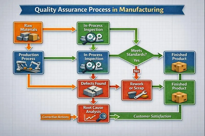
Process for Formulating a Project-Specific Quality Procedure
Step 1: Review the Project Scope
The QA/QC professional should begin by reviewing:
Contract documents.
Project specifications.
Engineering drawings.
Datasheets.
Equipment schedules.
Procurement specifications.
Construction methods.
Applicable codes.
Applicable standards.
Manufacturer requirements.
Client inspection requirements.
Regulatory requirements.
The purpose is to understand exactly what is being constructed, supplied, installed, inspected, tested, and handed over.
Step 2: Identify Quality-Critical Activities
Not every activity presents the same level of quality risk. Quality-critical activities should be identified using engineering judgement and risk assessment.
Examples include:
Pressure-containing fabrication.
Critical welds.
Rotating equipment alignment.
Safety-critical mechanical components.
High-pressure testing.
High-temperature equipment.
Critical material selection.
Precision machining.
Equipment foundations.
Critical bolted connections.
Final performance testing.
Step 3: Identify Applicable Requirements
Each activity should be linked to its governing requirements.
These may include:
Contract specifications.
Approved drawings.
Design calculations.
Codes.
Standards.
Manufacturer instructions.
Inspection specifications.
Acceptance criteria.
Step 4: Define Responsibilities
The procedure should clearly allocate responsibility to:
Project Quality Manager.
QA Manager.
QC Manager.
Mechanical QC Inspector.
Welding Inspector.
NDT personnel.
Materials Controller.
Construction Manager.
Mechanical Supervisor.
Supplier.
Subcontractor.
Client representative.
Third-party inspector.
Responsibilities should identify who performs, verifies, reviews, approves, records, and releases each activity.
Step 5: Define Required Competence
Quality procedures should identify competency requirements for specialist activities.
These may include:
Mechanical inspection competence.
Welding inspection competence.
NDT qualifications.
Equipment-specific training.
Measurement competence.
Code knowledge.
Calibration awareness.
Document-control competence.
This prevents technically important inspections from being assigned to personnel without appropriate competence.
Developing Material Inspection Plans
Material inspection is one of the most important elements of mechanical QA/QC because material characteristics directly influence strength, durability, corrosion resistance, weldability, pressure containment, reliability, and service life.
A Material Inspection Plan should control materials from the procurement stage through final installation.
Material Procurement Controls
Material requirements should be clearly defined in procurement documentation.
The purchase specification may establish:
Material grade.
Applicable material standard.
Product form.
Dimensions.
Chemical requirements.
Mechanical properties.
Heat-treatment condition.
Testing requirements.
Certification requirements.
Traceability requirements.
Surface-condition requirements.
Preservation requirements.
Poorly defined procurement requirements can create quality problems before material even reaches the project site.
Supplier Quality Assessment
For critical materials and equipment, supplier capability should be assessed before procurement.
Evaluation may consider:
Manufacturing capability.
Technical competence.
Previous project experience.
Quality management arrangements.
Inspection resources.
Testing facilities.
Material traceability systems.
Non-conformance history.
Subcontractor management.
Certification capability.
Delivery performance.
Supplier quality should be treated as part of the project’s overall QA/QC system rather than as a separate procurement issue.
Material Certification Review
Material certificates provide documentary evidence of material characteristics and conformity. The certificate should be compared with the purchase specification and project requirements.
The QA/QC reviewer may verify:
Manufacturer identity.
Product identification.
Material grade.
Heat or batch number.
Dimensions.
Chemical composition where required.
Mechanical test results.
Heat treatment.
Applicable standard.
Inspection results.
Traceability information.
A certificate should not be accepted merely because it has been supplied. Its contents must be relevant to the actual material and project requirement.
Material Receiving Inspection
When material arrives at the workshop, warehouse, fabrication facility, or construction site, receiving inspection should verify both physical and documentary conformity.
Typical checks include:
Quantity.
Identification.
Material grade.
Heat number.
Dimensions.
Surface condition.
Corrosion.
Physical damage.
Packaging.
Certification.
Traceability.
Storage requirements.
The receiving inspector should compare the physical material against the approved documentation.
Material Disposition
Material that does not satisfy requirements may be:
Accepted.
Accepted subject to technical clarification.
Quarantined.
Rejected.
Returned to supplier.
Submitted for engineering evaluation.
Subjected to additional testing where technically justified.
No material should be released simply because the project schedule is under pressure.
Material Traceability Management
Traceability provides the link between the physical material and its documentary evidence.
A strong traceability chain may be:
Purchase Order → Supplier → Material Certificate → Heat/Batch Number → Physical Material → Fabricated Component → Inspection Record → Final Equipment
Traceability methods may include:
Permanent marking.
Temporary marking.
Heat-number transfer.
Material tags.
Identification plates.
Barcode systems.
Digital registers.
Material allocation records.
Weld maps.
Component identification numbers.
Loss of traceability can become a major quality issue because the project may no longer be able to demonstrate that the installed material is the same material covered by the approved certificate.
Developing an Inspection and Test Plan
The ITP converts quality requirements into defined inspection and verification stages.
A comprehensive ITP should identify:
Work activity.
Inspection stage.
Responsible organisation.
Inspection method.
Reference document.
Acceptance criteria.
Inspection frequency.
Required records.
Hold points.
Witness points.
Review points.
Release requirements.
The ITP should be developed from the project requirements matrix rather than copied from an unrelated project.
Hold Points
A hold point is a mandatory stage where work cannot continue until the required inspection or approval has been completed.
Possible hold points include:
Material release.
Critical fit-up.
Critical welding stage.
Pressure testing.
Final dimensional inspection.
Equipment release.
Hold points should be established based on contractual and technical requirements.
Witness Points
A witness point provides an opportunity for a client, consultant, or third party to observe an inspection or test.
Potential witness activities include:
Pressure testing.
Performance testing.
Functional testing.
Selected NDT.
Final inspection.
The project procedure should define the notification and release process associated with witness points.
Establishing Clear Acceptance Criteria
An inspection activity is incomplete unless the inspector knows what constitutes acceptance.
Acceptance criteria may be derived from:
Applicable code.
Applicable standard.
Approved drawing.
Technical specification.
Datasheet.
Manufacturer requirements.
Approved procedure.
Contract requirement.
Acceptance criteria should be:
Specific.
Measurable where possible.
Traceable.
Technically justified.
Consistent with the approved design.
Clearly communicated.
For example, a dimensional inspection report should identify the specified dimension, tolerance, actual measurement, measuring instrument, calibration status where required, and final result.
Welding and NDT Quality Controls
Where mechanical fabrication involves welding, the material inspection plan must interface with the welding quality system.
Controls may include:
Base-material identification.
Consumable verification.
Welding procedure qualification.
Welder qualification.
Joint preparation.
Fit-up inspection.
Preheat verification.
Interpass-temperature control.
Welding parameter control.
Visual inspection.
NDT.
Repair control.
Final weld traceability.
ASME Section IX provides a framework for welding, brazing and fusing qualifications where the ASME code is applicable. ASME Section V addresses nondestructive examination.
ISO 17635:2025 provides general rules for selecting NDT methods and evaluating results for welds in metallic materials, considering factors such as quality requirements, material, weld thickness, welding process, and extent of testing. It is important to recognise that the applicable project code or specification ultimately determines the required inspection and acceptance basis.
Material Inspection and Testing Process
A robust material inspection process can be structured as follows:
Review purchase requirements.
Approve supplier where required.
Review manufacturing documentation.
Review material certificates.
Receive material.
Verify identification.
Verify dimensions.
Inspect physical condition.
Confirm traceability.
Conduct required testing.
Record results.
Quarantine non-conforming material.
Release conforming material.
Maintain traceability during fabrication.
Link material records to completed equipment.
This lifecycle approach ensures that material quality is controlled proactively rather than checked only after fabrication.
Practical Example: Pressure Vessel Material Inspection
Consider a large pressure vessel fabricated from certified steel plate. Several plates arrive at the fabrication facility with material certificates.
The QA/QC team should:
Verify purchase order requirements.
Confirm specified material grade.
Review certificates.
Verify heat numbers.
Check plate dimensions.
Examine surface condition.
Confirm traceability.
Record receiving inspection.
Release compliant material.
Quarantine discrepancies.
If one plate carries a heat number that does not match its certificate, the plate should not be released automatically.
The team should investigate whether:
The physical marking is incorrect.
The certificate is incorrect.
The wrong material was supplied.
Traceability was lost.
Additional verification is required.
This demonstrates the importance of objective evidence in material acceptance.
Practical Example: Centrifugal Pump Installation
For a large centrifugal pump, a project-specific mechanical installation procedure may establish controls for:
Foundation inspection.
Equipment identification.
Baseplate condition.
Anchor-bolt verification.
Levelling.
Alignment.
Soft-foot verification where applicable.
Coupling inspection.
Lubrication.
Piping connection.
Bolt verification.
Rotation checks.
Functional testing.
Final documentation.
The ITP then identifies when each activity is inspected and whether the inspection is a hold, witness, review, or surveillance point.
This distinction is important:
The procedure explains how the activity is controlled; the ITP explains when and how conformity is verified.
Practical Example: Welded Mechanical Assembly
For a critical welded assembly, the quality system could establish:
Material identification.
Joint preparation.
Approved welding procedure.
Welder qualification.
Fit-up inspection.
Preheat verification.
Welding monitoring.
Visual examination.
NDT.
Repair control.
Final acceptance.
The NDT method should be selected according to the project requirements and applicable standard rather than simply because a particular method is commonly used. ISO 17635:2025 specifically addresses selection of NDT methods and evaluation considerations for metallic welds.
Non-Conformance Management
A material or mechanical component that fails an inspection should enter a controlled non-conformance process.
Recommended NCR Process
Identify the non-conformity.
Stop or contain affected work.
Identify affected material or equipment.
Raise the NCR.
Assess technical significance.
Determine disposition.
Obtain required engineering/client approval.
Implement corrective action.
Re-inspect or re-test.
Verify effectiveness.
Close the NCR.
Capture lessons learned.
Possible dispositions include:
Repair.
Rework.
Replacement.
Rejection.
Additional testing.
Approved concession.
Engineering evaluation where permitted.
The objective should be to control both the immediate defect and its underlying cause.
Quality Documentation and Objective Evidence
A project-specific quality procedure should define all records required to demonstrate conformity.
Typical records include:
Material certificates.
Receiving inspection reports.
Material registers.
Traceability records.
Inspection requests.
Dimensional reports.
Welding records.
NDT reports.
Calibration certificates.
Pressure-test records.
Equipment inspection reports.
NCRs.
Corrective-action records.
Approved deviations or concessions.
Final inspection reports.
Release certificates.
Quality dossiers.
Quality records should remain identifiable and traceable to the relevant component or equipment.
Document and Revision Control
Using an outdated drawing, specification, procedure, or acceptance criterion can invalidate an otherwise competent inspection.
Document-control arrangements should ensure:
Current approved documents are available.
Obsolete revisions are withdrawn.
Electronic copies are controlled.
Inspection forms match current requirements.
Changes are formally reviewed.
Personnel are informed of relevant revisions.
Records remain protected and retrievable.
Revision control is especially important when changes affect:
Material grade.
Component dimensions.
Welding requirements.
NDT requirements.
Testing conditions.
Acceptance criteria.
Equipment configuration.
Supplier and Subcontractor Quality Control
For major mechanical projects, supplier and subcontractor quality must be incorporated into the overall project QA/QC framework.
Supplier controls may include:
Prequalification.
Quality-plan review.
ITP review.
Procedure review.
Supplier audits.
Source inspection.
Manufacturing surveillance.
Material-document review.
Witness testing.
Final inspection.
Documentation review.
This ensures that equipment manufactured thousands of kilometres away is controlled to the same project requirements as equipment fabricated at the main site.
Quality Auditing of Procedures and Inspection Plans
Once procedures and ITPs are implemented, audits should verify whether they are actually effective.
Audits can assess:
Compliance with approved procedures.
Correct use of ITPs.
Material traceability.
Inspection records.
Code references.
Calibration status.
NCR management.
Supplier performance.
Competency.
Document control.
Corrective actions.
An audit should not merely determine whether paperwork exists. It should establish whether the quality system is effectively controlling engineering risk.
Key Benefits of Project-Specific Quality Procedures
Quality Benefits
Consistent inspection practices.
Clear responsibilities.
Defined acceptance criteria.
Improved material traceability.
Better defect prevention.
Reduced rework.
Improved conformity.
Stronger inspection evidence.
Project Benefits
Reduced quality-related delays.
Improved supplier performance.
Better schedule predictability.
More efficient inspection planning.
Improved commissioning readiness.
Stronger handover documentation.
Better client confidence.
Risk Benefits
Improved control of critical equipment.
Reduced risk of incorrect materials.
Better control of pressure-containing systems.
Reduced risk of undocumented deviations.
Earlier identification of quality failures.
Commercial Benefits
Reduced cost of rework.
Reduced repair expenditure.
Lower risk of claims caused by poor quality evidence.
Better control of supplier performance.
Improved lifecycle reliability.
Reduced cost associated with late-stage defects.
Case Study: Developing a Project-Specific QA/QC System
Project Background
A multinational engineering contractor is delivering a large process facility containing pressure vessels, heat exchangers, pumps, compressors, tanks, valves, mechanical piping, and associated mechanical systems. Major equipment is being manufactured by different international suppliers before transportation to the project site.
The contract contains client specifications, engineering standards, material requirements, inspection requirements, testing requirements, and documentation requirements.
The contractor initially proposes its corporate QA/QC procedures.
Quality Challenge
During review, the project QA/QC manager identifies several weaknesses:
Generic material inspection requirements.
Incomplete material traceability.
Inconsistent certificate verification.
Unclear supplier inspection responsibilities.
Inadequate definition of hold points.
Ambiguous NDT references.
Missing project-specific acceptance criteria.
Incomplete quality-record requirements.
Simply approving the corporate procedures would create a risk that important project requirements would not be properly controlled.
Professional Response
The QA/QC team develops a project-specific requirements matrix and maps each requirement to:
Applicable code.
Applicable standard.
Quality procedure.
ITP.
Inspection record.
Acceptance criterion.
Responsible organisation.
Final quality dossier.
The revised documentation includes:
Project Quality Plan.
Material Control Procedure.
Material Inspection Plan.
Welding Control Procedure.
NDT Procedure.
Mechanical Equipment Installation Procedure.
Pressure Testing Procedure.
NCR Procedure.
Supplier Quality Procedure.
Calibration Procedure.
Document Control Procedure.
Final Dossier Procedure.
Result
The revised framework provides:
Clear inspection responsibilities.
Improved material traceability.
Consistent certificate verification.
Better supplier control.
Defined inspection stages.
Clear acceptance criteria.
Stronger client involvement.
Improved quality documentation.
Better readiness for final handover.
The case demonstrates why a project-specific QA/QC framework should be developed from actual requirements rather than copied from previous projects.
Common Errors in Formulating Quality Procedures
Senior QA/QC professionals should avoid the following weaknesses:
Copying procedures from previous projects without review.
Referencing standards without confirming applicability.
Using superseded editions.
Failing to establish a standards register.
Creating ITPs without measurable acceptance criteria.
Failing to identify material-critical activities.
Losing material traceability.
Accepting incomplete certificates.
Failing to define responsibilities.
Using unqualified inspection personnel.
Establishing unnecessary inspection points without risk justification.
Ignoring supplier quality risks.
Failing to control document revisions.
Closing NCRs without addressing root causes.
Allowing production pressure to override mandatory quality requirements.
Professional Review Checklist
Quality Procedure Review
Before approval, the QA/QC professional should confirm that the procedure:
Defines its purpose and scope.
Identifies project requirements.
References applicable codes and standards.
Uses the correct approved revisions.
Defines responsibilities.
Establishes competency requirements.
Defines inspection and testing activities.
Establishes acceptance criteria.
Identifies required records.
Controls non-conforming work.
Addresses traceability.
Links with applicable ITPs.
Includes document-control requirements.
Has undergone technical review and approval.
Material Inspection Plan Review
The material inspection plan should verify:
Material grade.
Material specification.
Purchase requirements.
Supplier documentation.
Certificate requirements.
Heat or batch traceability.
Receiving inspection.
Dimensional verification.
Surface-condition inspection.
Testing requirements.
Storage and preservation.
Non-conforming material controls.
Material release process.
Final traceability records.
Advanced Level 6 Considerations
At Level 6, formulation of quality procedures should demonstrate professional judgement rather than simple procedural compliance. The QA/QC professional should understand that quality controls must be proportionate to risk, technically justified, contractually compliant, and operationally practical.
A strong system should balance:
Quality and cost.
Quality and schedule.
Inspection and productivity.
Prevention and verification.
Documentation and practical usability.
Supplier flexibility and technical compliance.
Client involvement and project efficiency.
The professional should also recognise that excessive inspection does not automatically produce better quality. If a process is poorly designed, adding more final inspection may simply detect more defects without preventing their recurrence. Conversely, reducing inspections without considering risk can expose the project to unacceptable technical or commercial consequences.
The most effective approach is therefore a risk-based, process-oriented, evidence-driven QA/QC system.
Conclusion
Formulating clear project-specific quality procedures and material inspection plans is a core capability for advanced mechanical QA/QC professionals. Effective procedures translate project specifications, engineering requirements, contractual obligations, applicable international codes, standards, manufacturer requirements, and quality objectives into practical controls that can be consistently implemented across procurement, fabrication, installation, inspection, testing, commissioning, and handover. ISO 10005:2018 provides specific guidance for developing and managing quality plans, while international mechanical standards such as applicable ASME and ISO documents provide technical frameworks for materials, welding, NDT, pressure equipment, and related activities.
A robust Material Inspection Plan establishes control from purchase specification and supplier selection through material certification, receiving inspection, identification, traceability, storage, fabrication, testing, release, and final documentation. Similarly, a well-designed ITP connects each important activity with its responsible party, inspection stage, acceptance criterion, intervention point, and required record. For Level 6 learners, the essential professional skill is not merely knowing the names of international codes and standards, but being able to interpret project requirements and convert them into measurable, risk-based, auditable, and technically defensible quality controls. When properly implemented, project-specific QA/QC procedures strengthen mechanical integrity, reduce non-conformities and rework, improve supplier performance, support contractual compliance, protect project schedules and costs, and provide reliable objective evidence that the completed mechanical engineering work satisfies the required quality standards.
4: Establish Clear Lines of Communication and Documentation Workflows to Ensure All Project Teams Follow the Developed QA/QC Management System Correctly
Large-scale mechanical engineering projects involve multiple teams, organisations, disciplines, suppliers, subcontractors, consultants, inspectors, engineers, construction personnel, commissioning teams, and client representatives. Each group contributes information that can influence quality, and a breakdown in communication between any of these parties can result in incorrect work, duplicated inspections, missed hold points, uncontrolled design changes, material traceability problems, delayed corrective actions, or incomplete quality records. A technically strong QA/QC management system can therefore fail if project personnel do not receive the correct information at the correct time and through a controlled communication channel.
Establishing clear lines of communication and documentation workflows is consequently a fundamental responsibility of advanced QA/QC management. Communication should not depend on informal conversations, personal assumptions, uncontrolled emails, or verbal instructions. Instead, the project should establish defined reporting relationships, document responsibilities, approval routes, transmittal procedures, inspection-request workflows, technical-query processes, non-conformance reporting, change-control mechanisms, meeting structures, escalation arrangements, and quality-record systems. The objective is to ensure that every person performing or verifying mechanical work understands which requirements apply, which document revision is current, who has authority to approve a decision, and what evidence must be retained.
For Level 6 QA/QC professionals, effective communication management involves much more than distributing documents. It requires designing a controlled information system that connects engineering requirements with procurement, fabrication, inspection, installation, testing, commissioning, and handover. ISO 9001:2015 places emphasis on controlled information, communication, documented information, operational control, performance evaluation, and continual improvement, providing a useful quality-management foundation for establishing reliable documentation and communication processes. The exact project workflow should, however, be developed according to the contract, client requirements, applicable standards, project organisation, information-management arrangements, and regulatory environment.
Understanding QA/QC Communication in Mechanical Engineering Projects
QA/QC communication is the structured exchange of quality-related information between people and organisations involved in a project. It includes technical requirements, inspection instructions, approvals, quality alerts, test results, non-conformances, corrective actions, design changes, material information, audit findings, and quality performance data.
Effective communication should ensure that information is:
- Accurate.
- Clear.
- Timely.
- Traceable.
- Authorised.
- Relevant.
- Controlled.
- Accessible to the appropriate personnel.
- Protected against unauthorised changes.
- Retained as objective evidence where required.
Communication failures can have direct technical consequences. For example, if a revised mechanical drawing is issued but the fabrication team continues using the previous revision, components may be manufactured incorrectly. If a material hold point is not communicated to the inspection team, material may be released before verification. If an NCR is not communicated to affected departments, similar defective work may continue elsewhere.
The QA/QC communication system must therefore function as an integral part of the engineering management system.
Key Definitions and Concepts
| Term | Definition | Mechanical QA/QC Application |
|---|---|---|
| Communication Workflow | Defined route through which quality information is created, reviewed, approved and distributed | Controls how inspection, engineering and quality information reaches project teams |
| Document Control | System for managing document identification, revision, approval, distribution and retention | Prevents use of obsolete drawings and procedures |
| Documented Information | Controlled information required by the management system or project | Includes procedures, records, reports, certificates and inspection evidence |
| Transmittal | Controlled record used to formally issue documents or information | Provides evidence of what was transmitted, to whom and when |
| Inspection Request | Formal notification requesting inspection or verification | Initiates defined inspection activities |
| Technical Query | Controlled communication used to obtain technical clarification | Prevents teams from relying on assumptions |
| NCR | Formal record identifying non-conforming work or material | Communicates quality failure and controls corrective action |
| Quality Alert | Formal communication highlighting an important quality concern or lesson | Helps prevent recurrence across the project |
| RFI | Request for information used to clarify technical or project information | Supports controlled resolution of uncertainties |
| Distribution Matrix | Defined list identifying who should receive specific information | Ensures relevant teams receive required documents |
| Document Register | Controlled list of project documents and their current status | Provides visibility of document revisions and approval status |
| Quality Record | Evidence demonstrating that required quality activities were completed | Supports audits, acceptance and project handover |
| Escalation | Formal process for moving unresolved issues to higher authority | Prevents critical quality issues from remaining unresolved |
Why Communication Is Critical to QA/QC Performance
Mechanical engineering projects are highly interconnected. A change introduced by one department can affect several other departments.
For example, a change in material grade may affect:
- Engineering calculations.
- Procurement.
- Material certification.
- Welding procedures.
- Welder qualifications.
- NDT requirements.
- Fabrication.
- Installation.
- Testing.
- Documentation.
- Final equipment records.
If the change is communicated only to procurement, the downstream teams may continue working to obsolete requirements.
A mature QA/QC system therefore treats information as a controlled project resource.
Effective communication supports:
- Consistent implementation of procedures.
- Correct interpretation of technical requirements.
- Timely inspection.
- Proper release of hold points.
- Effective NCR management.
- Accurate material traceability.
- Controlled design changes.
- Timely corrective action.
- Reliable quality reporting.
- Complete handover documentation.
Establishing a QA/QC Communication Structure
The first step is to define who communicates with whom and for what purpose.
A typical mechanical project structure may include:
- Project Director.
- Project Manager.
- Engineering Manager.
- QA/QC Manager.
- Mechanical QA/QC Engineer.
- QC Inspectors.
- Construction Manager.
- Mechanical Superintendent.
- Procurement Manager.
- Materials Manager.
- Document Controller.
- Planning Manager.
- Commissioning Manager.
- Supplier representatives.
- Subcontractors.
- Client representatives.
- Third-party inspectors.
The exact organisational structure will vary, but responsibilities should be clearly documented.
Defining Communication Responsibilities
Each role should understand:
- What information it must generate.
- What information it must review.
- What information it must approve.
- What information it must distribute.
- What records it must maintain.
- When escalation is required.
- Which communication channels are authorised.
This prevents both communication gaps and unnecessary duplication.
QA/QC Communication Matrix
A communication matrix can identify the required communication type, responsible person, recipient, frequency, method, and record.
Typical communication activities include:
- Daily inspection coordination.
- Weekly quality meetings.
- Monthly quality performance reports.
- Inspection requests.
- Technical queries.
- NCR notifications.
- Corrective-action updates.
- Supplier quality reports.
- Quality alerts.
- Audit notifications.
- Test notifications.
- Design-change notifications.
- Client submissions.
The communication matrix should be reviewed when the project organisation changes.
Documentation Workflow
A documentation workflow defines how information moves from creation to approval, issue, implementation, revision, storage, and final archiving.
A typical workflow is:
Project Requirement
↓
Document Preparation
↓
Technical Review
↓
QA/QC Review
↓
Approval
↓
Controlled Issue
↓
Distribution
↓
Implementation
↓
Inspection/Verification
↓
Record Generation
↓
Review
↓
Final Acceptance
↓
Archiving
This workflow creates traceability between the original requirement and the evidence demonstrating implementation.
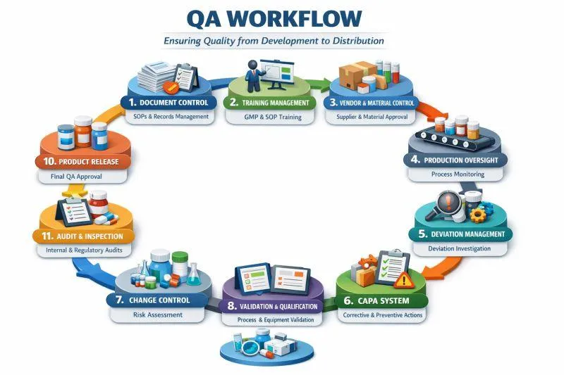
Document Creation and Identification
Every controlled QA/QC document should have a unique identification system.
Document identification may include:
- Project code.
- Discipline code.
- Document type.
- Sequential number.
- Revision.
- Status.
- Date.
For example, a project may use separate identification structures for:
- Procedures.
- ITPs.
- Inspection forms.
- Reports.
- Drawings.
- Test certificates.
- NCRs.
- Audit reports.
The precise coding system should be established by the project document-control procedure.
Document Review and Approval
Documents should pass through defined review and approval stages before being used for quality-critical activities.
Depending on the document, review may involve:
- Engineering.
- QA/QC.
- Construction.
- Procurement.
- Commissioning.
- Client.
- Third-party inspection.
A procedure should identify which roles have authority to approve each document.
Approval should confirm that:
- Technical requirements are correctly interpreted.
- Applicable standards have been identified.
- Inspection requirements are adequate.
- Responsibilities are clear.
- Acceptance criteria are defined.
- Interfaces are addressed.
- Required records are identified.
Revision Control
Revision control is one of the most important components of a mechanical QA/QC documentation system.
A document may change because of:
- Engineering modifications.
- Client comments.
- Regulatory changes.
- Construction feedback.
- Quality findings.
- Lessons learned.
- Corrective actions.
- Equipment changes.
- Supplier information.
When a document is revised, the project should ensure that:
- The new revision is formally approved.
- Previous versions are identified as superseded.
- Controlled users receive the new version.
- Obsolete copies are withdrawn.
- Relevant personnel are informed.
- Activities already performed under previous requirements are evaluated where necessary.
Controlling Drawings and Technical Documents
Mechanical fabrication and installation depend heavily on controlled drawings.
Drawings may include:
- General arrangement drawings.
- Fabrication drawings.
- Piping drawings.
- Equipment drawings.
- Assembly drawings.
- Isometric drawings.
- Detail drawings.
- Foundation drawings.
- Installation drawings.
- As-built drawings.
The QA/QC team should verify that inspection activities are performed against the correct approved revision.
A drawing-control workflow should therefore include:
- Receipt.
- Registration.
- Technical review.
- Approval.
- Distribution.
- Revision tracking.
- Withdrawal of obsolete versions.
- Archive.
Inspection Request Workflow
Inspection requests are a critical communication link between construction and QA/QC teams.
A typical workflow may be:
- Construction completes the defined activity.
- Supervisor checks the work internally.
- Required documents are confirmed.
- Inspection request is submitted.
- QC inspector reviews the request.
- Inspection is performed.
- Results are recorded.
- Deficiencies are communicated.
- Re-inspection occurs if required.
- Inspection status is recorded.
- Work is released or NCR action is initiated.
The process prevents inspectors from being called to incomplete or undocumented work.
Hold Point Communication
Hold points require particularly strong communication because work may not proceed until the defined inspection or approval has occurred.
The project should establish:
- Who owns the hold point.
- Who must be notified.
- Minimum notification period.
- Required supporting documents.
- Inspection location.
- Acceptance criteria.
- Release authority.
- Required record.
- Escalation route if the hold point is delayed.
Failure to communicate a hold point can result in unauthorised progression of work and potentially require destructive examination, rework, or other costly verification.
Witness Point Communication
Witness points also require formal notification.
The notification should identify:
- Activity.
- Location.
- Equipment.
- Date and time.
- Applicable procedure.
- Inspection requirement.
- Required documents.
- Responsible contact.
If the project contract specifies particular rules for proceeding when a witness does not attend, those requirements must be followed.
Technical Query and Clarification Workflow
Mechanical projects frequently encounter unclear or conflicting technical information.
Examples include:
- Drawing conflict.
- Specification ambiguity.
- Unclear tolerance.
- Material substitution request.
- Installation constraint.
- Unexpected site condition.
- Equipment interface issue.
Personnel should not resolve significant technical uncertainty through informal verbal decisions.
A controlled technical-query workflow may involve:
- Identify the issue.
- Describe the problem clearly.
- Reference affected documents.
- Explain the potential impact.
- Submit the query.
- Engineering reviews the issue.
- QA/QC assesses quality implications.
- Relevant stakeholders provide input.
- Authorised decision is issued.
- Documents are updated where necessary.
- The decision is communicated.
- Records are retained.
This provides a traceable history of the technical decision.
Non-Conformance Communication Workflow
NCRs must be communicated promptly to affected parties.
A typical NCR workflow includes:
- Defect identified.
- Work or material contained.
- NCR raised.
- Relevant parties notified.
- Technical assessment performed.
- Root cause investigated.
- Disposition established.
- Corrective action assigned.
- Corrective action completed.
- Re-inspection performed.
- Effectiveness verified.
- NCR closed.
- Lessons learned communicated.
The NCR should not remain isolated within the QA/QC department if the defect could affect other areas of the project.
Quality Alerts and Lessons Learned
A quality alert is useful when a particular defect or risk could occur elsewhere.
For example, if a supplier repeatedly provides components with incorrect identification markings, a quality alert can be issued to other receiving and inspection teams.
A quality alert may communicate:
- What happened.
- Where it happened.
- Why it happened.
- What risk it created.
- What teams should check.
- What preventive action is required.
This converts individual experience into organisational learning.
Digital Documentation Workflows
Modern mechanical engineering projects increasingly use digital document-management and common data environments. Digital systems can improve:
- Document accessibility.
- Revision control.
- Searchability.
- Approval tracking.
- Inspection reporting.
- Audit trails.
- Data analysis.
- Quality dashboards.
- Handover preparation.
However, digital systems do not automatically create effective document control. The project must establish rules for:
- User permissions.
- Document status.
- Approval authority.
- Revision control.
- Naming conventions.
- Metadata.
- Electronic signatures where applicable.
- Data retention.
- Backup.
- Access control.
Quality Record Management
Quality records provide evidence that required activities were completed.
Typical records include:
- Material certificates.
- Inspection reports.
- Test reports.
- NDT reports.
- Welding records.
- Calibration certificates.
- Equipment release records.
- NCRs.
- Corrective-action reports.
- Audit reports.
- Supplier inspection records.
- Pressure-test certificates.
- Final quality dossiers.
Each record should be linked to the relevant:
- Project.
- Equipment.
- Tag number.
- Component.
- Work package.
- Inspection activity.
- Drawing revision.
- Material identification.
Quality Dossier Workflow
The final quality dossier should not be assembled only at project completion.
A better approach is progressive compilation.
Progressive Dossier Process
- Establish dossier index.
- Define required records.
- Assign document owners.
- Collect records progressively.
- Review records.
- Identify missing documents.
- Correct documentation gaps.
- Verify traceability.
- Complete final review.
- Submit for approval.
- Archive controlled final version.
Progressive compilation prevents the common problem of discovering hundreds of missing records during final handover.
Communication Between Engineering and QA/QC
Engineering and QA/QC teams must maintain strong communication because quality requirements originate largely from engineering information.
Important interfaces include:
- Design changes.
- Material specifications.
- Welding requirements.
- Dimensional tolerances.
- Testing criteria.
- Equipment interfaces.
- Technical deviations.
- Non-conformance disposition.
- Concessions.
- As-built information.
Engineering should be informed of quality findings that indicate potential design weaknesses, while QA/QC should receive relevant engineering changes before affected work is performed.
Communication Between Procurement and QA/QC
Procurement should communicate quality-critical supplier information to QA/QC.
This may include:
- Purchase specifications.
- Approved suppliers.
- Supplier deviations.
- Manufacturing schedules.
- Inspection dates.
- Material certificates.
- Supplier NCRs.
- Delivery changes.
- Subcontracting arrangements.
QA/QC should, in turn, communicate quality requirements that suppliers must satisfy.
Communication Between Construction and QA/QC
Construction teams are responsible for executing physical work, while QA/QC provides independent or defined verification according to the project quality system.
Effective communication should cover:
- Planned inspections.
- Inspection requests.
- Hold points.
- Witness points.
- Work readiness.
- Deficiencies.
- NCRs.
- Re-inspection.
- Quality trends.
- Upcoming critical activities.
Communication should be constructive and focused on preventing quality failures rather than creating conflict between production and quality teams.
Communication During Testing and Commissioning
Mechanical testing and commissioning require close coordination because several disciplines may be involved.
Information may need to flow between:
- Mechanical.
- Electrical.
- Instrumentation.
- Process.
- QA/QC.
- Commissioning.
- Operations.
- Client.
- Vendor representatives.
Before testing, teams should confirm:
- Equipment readiness.
- Approved procedures.
- Calibration status.
- Safety requirements.
- Test boundaries.
- Test conditions.
- Acceptance criteria.
- Required personnel.
- Required documentation.
After testing, results should be formally recorded and reviewed.
Communication Escalation System
Not every issue can be resolved at the inspector level.
An escalation system should define when an issue moves to higher management.
Escalation may be required when:
- A critical component fails.
- A repeated defect occurs.
- A major NCR is identified.
- Contractual compliance is threatened.
- Work proceeds beyond a hold point.
- Material traceability is lost.
- A design conflict affects quality.
- Testing fails.
- Supplier performance deteriorates.
- Corrective actions remain overdue.
A typical escalation path may be:
Inspector → QC Engineer → QC Manager → QA Manager → Engineering Manager → Project Manager → Senior Management → Client
The exact route should be established by the project organisation.
Communication Meetings and Reporting
Regular meetings provide opportunities to identify emerging quality issues before they become major problems.
Daily Quality Coordination
Daily meetings may address:
- Planned inspections.
- Hold points.
- Witness points.
- Critical activities.
- NCR status.
- Material issues.
- Documentation gaps.
- Testing activities.
Weekly Quality Meeting
Weekly meetings can review:
- Quality KPIs.
- NCR trends.
- Supplier performance.
- Audit findings.
- Inspection performance.
- Major technical queries.
- Corrective actions.
- Upcoming quality risks.
- Client concerns.
Monthly Quality Review
Management-level reviews may assess:
- Overall quality performance.
- Major risks.
- Cost of poor quality.
- Supplier trends.
- System effectiveness.
- Resource requirements.
- Improvement opportunities.
Practical Example: Incorrect Drawing Revision
Scenario
A fabrication team begins manufacturing a mechanical support using Drawing Revision B. Engineering has already issued Revision C, which changes the support dimensions.
The drawing revision was not correctly distributed to the fabrication supervisor.
Potential Consequences
- Incorrect fabrication.
- Rework.
- Material wastage.
- Schedule delay.
- Additional inspection.
- Potential installation problems.
Corrective Communication Response
The project should:
- Stop affected work.
- Identify all components produced using Revision B.
- Notify QA/QC, engineering and construction.
- Determine whether existing components can be accepted.
- Raise an NCR if required.
- Distribute Revision C through controlled channels.
- Withdraw obsolete copies.
- Review document-distribution controls.
- Verify that other teams have the current revision.
The event should also be analysed to determine whether the problem was isolated or systemic.
Practical Example: Material Certificate Communication Failure
Scenario
A batch of alloy material is delivered to the fabrication area. The material has been physically identified, but the required certification has not been reviewed. The fabrication team plans to use the material immediately.
Correct Response
The QA/QC team should:
- Prevent uncontrolled use.
- Verify material identification.
- Locate the relevant certificate.
- Compare the certificate with the purchase requirements.
- Confirm traceability.
- Complete the required inspection.
- Release the material only after conformity is established.
The communication lesson is that material status must be visible to warehouse, fabrication, QA/QC and supervision teams.
Practical Example: Failed Pressure Test
Scenario
A mechanical piping system fails a pressure test. The construction team repairs the leaking joint and proposes immediate retesting.
A mature QA/QC system should ensure that the failure is formally communicated and recorded.
The process may include:
- Test failure notification.
- Identification of affected joint.
- Review of installation records.
- Assessment of repair method.
- NCR or test-failure record where required.
- Re-inspection.
- Controlled retesting.
- Review of similar joints.
- Trend assessment.
- Closure documentation.
This ensures that the test failure becomes a source of quality information rather than simply an isolated repair.
Case Study: Communication Breakdown in a Mechanical Project
Project Background
A large industrial project involves several international suppliers and subcontractors. The project uses multiple teams for equipment fabrication, piping, mechanical installation, inspection, and commissioning.
The project has an approved QA/QC management system, but quality problems begin to increase.
Identified Problems
The QA/QC team discovers:
- Different teams using different document revisions.
- Inspection requests submitted without supporting records.
- NCRs not communicated to affected subcontractors.
- Supplier documents arriving late.
- Engineering changes reaching construction after work has started.
- Quality-dossier records missing.
- Client comments not consistently incorporated.
The problem is not the absence of a QA/QC system. The problem is ineffective communication and document workflow.
Improvement Strategy
The project establishes:
- Controlled document register.
- Distribution matrix.
- Formal transmittal system.
- Daily quality coordination.
- Weekly quality meetings.
- Central NCR register.
- Technical-query workflow.
- Quality-alert system.
- Progressive dossier compilation.
- Document-revision verification.
- Escalation procedure.
Result
The project begins to experience:
- Fewer obsolete-document issues.
- Faster NCR communication.
- Improved inspection readiness.
- Better traceability.
- Earlier identification of quality risks.
- Improved supplier responsiveness.
- More complete handover records.
The case demonstrates that communication is not an administrative activity separate from quality management. It is one of the mechanisms through which the QA/QC system operates.
Key Benefits of Effective QA/QC Communication
Quality Benefits
- Better understanding of requirements.
- Reduced interpretation errors.
- Improved inspection readiness.
- Faster defect communication.
- Better corrective-action implementation.
- Reduced recurring defects.
- Improved traceability.
Project Benefits
- Reduced rework.
- Better schedule coordination.
- Fewer document-related delays.
- Improved supplier performance.
- More efficient inspections.
- Better commissioning readiness.
Management Benefits
- Clear accountability.
- Improved visibility.
- Better decision-making.
- Stronger escalation.
- More reliable reporting.
- Improved audit readiness.
Handover Benefits
- Complete quality records.
- Better equipment traceability.
- Faster dossier compilation.
- Improved client confidence.
- Stronger evidence of contractual compliance.
Common Communication and Documentation Failures
Senior QA/QC professionals should actively prevent:
- Verbal instructions being treated as formal approvals.
- Uncontrolled documents being used for inspection.
- Obsolete drawings remaining at work locations.
- Poorly defined distribution lists.
- Inspection requests submitted without readiness checks.
- NCRs not communicated to affected teams.
- Technical queries remaining unresolved.
- Quality records being created after the fact.
- Missing equipment identification.
- Incomplete material traceability.
- Unclear approval authority.
- Delayed escalation.
- Poor meeting records.
- Failure to communicate lessons learned.
Professional Procedure for Establishing the Communication Workflow
Phase 1: Identify Information Requirements
Determine:
- What information is required.
- Who generates it.
- Who reviews it.
- Who approves it.
- Who receives it.
- When it is required.
- How it is recorded.
Phase 2: Establish Communication Channels
Define approved channels for:
- Formal correspondence.
- Controlled documents.
- Inspection requests.
- Technical queries.
- NCRs.
- Quality alerts.
- Meetings.
- Emergency escalation.
Phase 3: Establish Document Control
Define:
- Document numbering.
- Revision control.
- Approval.
- Distribution.
- Withdrawal.
- Archiving.
- Access permissions.
Phase 4: Establish Inspection Communication
Define:
- Inspection request process.
- Hold-point notification.
- Witness-point notification.
- Inspection results.
- Re-inspection.
- Release.
Phase 5: Establish Problem Communication
Define:
- NCR process.
- Technical-query process.
- Corrective action.
- Escalation.
- Quality alerts.
- Lessons learned.
Phase 6: Establish Monitoring
Monitor:
- Document approval time.
- Inspection response time.
- NCR communication time.
- Corrective-action closure.
- Document revision compliance.
- Dossier completeness.
- Technical-query response time.
Phase 7: Continually Improve
Use:
- Audit findings.
- Quality KPIs.
- Lessons learned.
- User feedback.
- Recurring communication failures.
- Client feedback.
to improve the communication and documentation system.
Advanced Level 6 Professional Considerations
At Level 6, QA/QC professionals should recognise that communication workflows must support professional judgement and technical accountability. The goal is not to create unnecessary administrative procedures. The goal is to ensure that critical information reaches the right people before decisions are made or work proceeds.
A strong system should balance:
- Formal control and operational efficiency.
- Documentation and usability.
- Central control and project accessibility.
- Speed and accuracy.
- Production requirements and quality requirements.
- Client involvement and project autonomy.
The communication system should also be resilient to unpredictable project environments. If a supplier changes, a drawing is revised, a critical NCR is identified, or a test fails, the workflow should allow information to move quickly to every affected party.
Key Takeaways
The most important principles for establishing QA/QC communication and documentation workflows are:
- Define clear communication responsibilities.
- Establish formal reporting lines.
- Use controlled document systems.
- Maintain accurate document registers.
- Control drawing revisions.
- Define inspection-request workflows.
- Communicate hold and witness points clearly.
- Establish formal technical-query processes.
- Communicate NCRs promptly.
- Use quality alerts for transferable lessons.
- Maintain progressive quality dossiers.
- Integrate supplier communication.
- Coordinate engineering and QA/QC changes.
- Establish escalation procedures.
- Monitor communication performance.
- Protect quality records.
- Use digital systems with defined governance.
- Ensure all project personnel understand current requirements.
- Continually improve communication based on quality data.
Conclusion
Clear communication and controlled documentation are essential to ensuring that a mechanical engineering QA/QC management system is implemented consistently across a complex project organisation. Even the most technically comprehensive quality procedure can become ineffective if personnel do not know which revision applies, who has authority to approve an activity, when an inspection is required, what acceptance criteria must be used, or how a non-conformance should be communicated. Effective QA/QC communication therefore creates the operational link between quality planning and actual project execution.
For Level 6 QA/QC professionals, the objective is to establish a communication and documentation framework that is structured, traceable, timely, accessible, and proportionate to project risk. This should include controlled document management, defined communication matrices, inspection-request workflows, hold and witness point notifications, technical-query processes, NCR management, quality alerts, supplier communication, escalation arrangements, regular quality meetings, progressive quality-dossier compilation, and continual monitoring of communication performance. When these mechanisms operate effectively, project teams are more likely to work from consistent technical requirements, identify quality problems early, complete corrective actions efficiently, and produce reliable objective evidence of conformity. Ultimately, effective communication and documentation workflows strengthen mechanical integrity, reduce rework and information-related delays, support contractual compliance, improve stakeholder confidence, and help ensure successful project delivery from design and procurement through fabrication, installation, testing, commissioning, and final handover.