Lexiton International
Lexiton International Welcome to Lexiton International
Level 6 Diploma in Quality Assurance and Quality Control (QA/QC) Mechanical
Section 1: Unit 1: Advanced Quality Management Systems in Mechanical Engineering
Section 2: Unt No 2: Mechanical System Inspection and Testing Techniques
Section 3: Unit 3: Statistical Process Control and Data Analysis in Mechanical Engineering
Section 4: Unit No 4: Mechanical Components, Materials, and Reliability in QA/QC
Lesson 1: Assess properties and performance of mechanical components and materials used in projects. Quiz No 1: Assess properties and performance of mechanical components and materials used in projects. Lesson 2: Evaluate the reliability, safety, and suitability of components for operational conditions. Quiz no 2: Evaluate the reliability, safety, and suitability of components for operational conditions. Lesson 3: Predict potential failures and implement measures to prevent mechanical defects. Quiz No 3: Predict potential failures and implement measures to prevent mechanical defects. Lesson 4: Ensure long-term durability and performance of mechanical systems. Quiz No 4: Ensure long-term durability and performance of mechanical systems. Lesson 5: Recommend solutions to improve component quality, system efficiency, and safety. Quiz No 5: Recommend solutions to improve component quality, system efficiency, and safety. Lesson no 6 :Analyse environmental and load impacts on mechanical systems for QA/QC purposes. Quiz no 6 : Analyse environmental and load impacts on mechanical systems for QA/QC purposes.
Section 5: Unit no 5 : Compliance with International Mechanical Standards and Regulations
Section 6: Unit no 6 :Leadership, Risk Management, and Project Supervision in QA/QC Mechanical
Lesson 19

Lesson 1: Assess properties and performance of mechanical components and materials used in projects.

1. Critically evaluate the physical properties, such as tensile strength, hardness, and ductility, of different metals and alloys used in heavy mechanical projects

The selection and evaluation of metals and alloys are fundamental activities within mechanical engineering quality assurance and quality control because material behaviour directly influences component strength, durability, reliability, safety and service life. Heavy mechanical projects commonly involve shafts, pressure-containing components, structural frames, gears, pins, fasteners, couplings, housings, lifting components, rotating equipment, fabricated assemblies and wear-resistant parts. Each application exposes materials to different combinations of tensile loading, compression, bending, impact, vibration, friction, temperature and environmental degradation. A material that performs effectively in one application may be unsuitable for another, even when its nominal strength appears adequate.

Critical evaluation therefore requires more than identifying a material grade or reading a single value from a material certificate. A professional QA/QC assessment considers the relationship between tensile strength, yield behaviour, hardness, ductility, toughness, fatigue performance, manufacturing condition and the actual service environment. Material properties should be interpreted against the engineering function of the component, specified acceptance criteria, manufacturing process and anticipated failure mechanisms. This evidence-based approach supports informed decisions about material selection, incoming inspection, manufacturing control, component acceptance and long-term mechanical reliability.

Understanding physical properties in mechanical engineering

Physical and mechanical properties describe how a material responds when subjected to forces, deformation, contact or environmental conditions. In heavy mechanical engineering, these properties are rarely considered independently because changing one characteristic can influence other aspects of performance.

For example, increasing hardness through heat treatment may improve resistance to wear and indentation but can reduce ductility if the treatment is not properly controlled. Similarly, selecting a high-strength alloy may increase load-bearing capability while creating additional concerns related to welding, residual stress, fracture behaviour or fabrication control.

Important properties include:

  • Tensile strength.

  • Yield strength.

  • Hardness.

  • Ductility.

  • Toughness.

  • Fatigue resistance.

  • Elastic modulus.

  • Wear resistance.

  • Corrosion resistance.

  • Impact resistance.

  • Thermal stability.

  • Dimensional stability.

The correct interpretation depends on the intended component function.

Key definitions and concepts

Property or conceptDefinitionQA/QC significanceTypical engineering relevance
Tensile strengthMaximum tensile stress a material withstands before failureConfirms resistance to tensile loadingShafts, fasteners, structural members
Yield strengthStress at which significant permanent deformation beginsHelps assess load-carrying capacityFrames, pressure components, rotating parts
HardnessResistance to indentation or local deformationSupports material verification and wear assessmentGears, shafts, wear surfaces
DuctilityAbility to undergo plastic deformation before fractureIndicates deformation toleranceFabricated structures and formed components
ToughnessAbility to absorb energy before fractureImportant for impact and crack resistanceHeavy-duty machinery and critical components
Fatigue resistanceAbility to withstand repeated cyclic loadingImportant for components exposed to vibrationShafts, gears, couplings
Elastic modulusRelationship between stress and elastic strainIndicates stiffnessStructural and precision components
Wear resistanceAbility to resist material loss from contactSupports service-life assessmentBearings, gears, sliding surfaces
Corrosion resistanceAbility to resist environmental degradationImportant for material durabilityOutdoor and chemical environments
Yield behaviourTransition from elastic to permanent deformationSupports structural integrity assessmentLoaded mechanical components

Tensile strength and its engineering significance
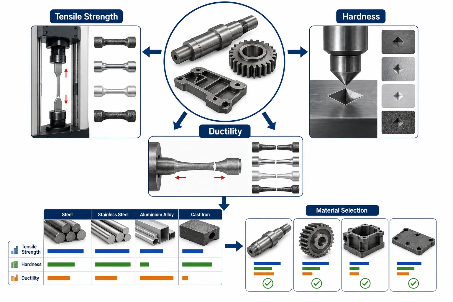
Material Properties and Selection Guide

Tensile strength represents the maximum tensile stress that a material can sustain during a tensile test before fracture occurs. It provides useful information about the ultimate load-bearing capability of the material under the conditions of the test.

However, tensile strength should not be treated as the only indicator of suitability.

A component may require:

  • High yield strength rather than simply high ultimate strength.

  • High ductility to accommodate deformation.

  • High toughness to resist fracture.

  • Good fatigue resistance for cyclic loading.

  • Appropriate corrosion resistance.

  • Adequate hardness for wear conditions.

For QA/QC purposes, tensile-test results should therefore be evaluated against the applicable material specification and intended service requirements.

Factors influencing tensile performance

Tensile performance can be influenced by:

  • Alloy composition.

  • Heat treatment.

  • Manufacturing process.

  • Grain structure.

  • Welding.

  • Cold working.

  • Temperature.

  • Defects.

  • Residual stresses.

  • Material condition.

Two components manufactured from nominally similar alloys may therefore demonstrate different performance if their processing histories differ.

Yield strength versus tensile strength

Yield strength and tensile strength provide different information.

Yield strength concerns the onset of significant permanent deformation, whereas tensile strength represents the maximum stress reached during a tensile test.

This distinction is important in heavy mechanical projects because permanent deformation may represent unacceptable service behaviour even when the component has not fractured.

For example, a heavily loaded structural bracket may remain intact but deform permanently. If the deformation affects alignment, clearance or load distribution, the component may no longer perform its intended function.

A QA/QC professional should therefore consider:

  • Required design load.

  • Allowable stress.

  • Yield strength.

  • Ultimate tensile strength.

  • Safety factors.

  • Service temperature.

  • Loading frequency.

  • Component geometry.

Hardness and its practical importance

Hardness describes resistance to localised deformation, commonly assessed through indentation-based methods. Hardness testing is widely used in mechanical QA/QC because it can provide relatively rapid evidence about material condition.

Hardness can be relevant to:

  • Wear resistance.

  • Heat-treatment verification.

  • Surface condition.

  • Material identification.

  • Production consistency.

  • Quality control of machined or treated components.

Typical hardness testing methods include:

  • Rockwell.

  • Brinell.

  • Vickers.

The appropriate method depends on material type, component geometry, surface condition and testing requirements.

Interpreting hardness results

A hardness result should not be interpreted in isolation.

An unusually high hardness value may indicate:

  • Incorrect heat treatment.

  • Excessive cold working.

  • Material substitution.

  • Localised hardening.

  • Testing problems.

An unusually low value may indicate:

  • Inadequate heat treatment.

  • Incorrect material condition.

  • Over-tempering.

  • Material mix-up.

  • Surface preparation problems.

The QA/QC professional should compare the result with the relevant acceptance criteria and investigate significant deviations.

Hardness and wear resistance

Hardness often correlates with resistance to certain forms of wear, but the relationship is not universal.

Wear behaviour also depends on:

  • Contact pressure.

  • Lubrication.

  • Surface finish.

  • Counterface material.

  • Temperature.

  • Particle contamination.

  • Contact geometry.

  • Loading cycle.

A highly hardened gear surface may provide excellent wear resistance, but excessive hardness or inadequate toughness can create other risks.

Ductility and its importance

Ductility describes the capacity of a material to undergo plastic deformation before fracture.

Ductile materials can often tolerate a degree of deformation before failure, providing warning through permanent deformation.

Ductility can be especially important for:

  • Fabricated structures.

  • Formed components.

  • Pressure-containing components.

  • Welded assemblies.

  • Components subject to overload.

  • Components where sudden fracture would create significant risk.

A material with high tensile strength but very low ductility may require careful assessment because strength alone does not describe its fracture behaviour.

Measuring ductility

Ductility is commonly evaluated using tensile-test measurements such as:

  • Percentage elongation.

  • Reduction of area.

These values provide information about how much plastic deformation occurs before fracture.

QA/QC assessment should compare the measured result with the relevant material requirements rather than relying on generic assumptions about a material family.

Relationship between strength, hardness and ductility

A key engineering principle is that material properties interact.

In many steels, increasing strength and hardness through particular heat-treatment routes can be accompanied by reduced ductility.

This creates an engineering trade-off.

For example:

A gear may require high surface hardness to resist wear, but sufficient toughness and ductility in the underlying material may be required to prevent brittle failure.

Therefore, the best material is not necessarily the hardest or strongest material.

The best material is one whose combined properties are suitable for the intended service conditions.

Evaluating common metals and alloys

Carbon steels

Carbon steels are widely used in heavy mechanical engineering because they offer useful combinations of strength, machinability, availability and cost.

Their properties vary considerably with carbon content and processing condition.

Typical applications include:

  • Structural components.

  • Shafts.

  • Plates.

  • Frames.

  • General machinery.

  • Fasteners.

  • Fabricated components.

QA/QC assessment should consider:

  • Grade.

  • Carbon content.

  • Mechanical properties.

  • Heat treatment.

  • Weldability.

  • Surface condition.

  • Material certification.

Higher carbon content can generally increase strength and hardness but may influence ductility and weldability.

Low-alloy steels

Low-alloy steels contain controlled additions of alloying elements that modify mechanical performance.

Potential advantages include:

  • Higher strength.

  • Improved hardenability.

  • Better fatigue performance.

  • Improved toughness in selected conditions.

  • Better performance at elevated temperatures for appropriate grades.

Applications may include:

  • Heavy-duty shafts.

  • Gears.

  • Pressure-related equipment.

  • Structural machinery components.

  • High-load mechanical parts.

However, QA/QC assessment should pay particular attention to heat treatment, welding procedures and material traceability.

Stainless steels

Stainless steels are selected primarily where corrosion resistance is important, although their mechanical properties vary significantly between grades and conditions.

Applications can include:

  • Process equipment.

  • Pump components.

  • Fasteners.

  • Fabricated assemblies.

  • Chemical-processing equipment.

  • Food-processing machinery.

Relevant assessment characteristics include:

  • Tensile strength.

  • Yield strength.

  • Hardness.

  • Ductility.

  • Corrosion resistance.

  • Surface condition.

  • Weld quality.

The term “stainless steel” should not be treated as a single material category. Different grades have significantly different properties and service limitations.

Aluminium alloys

Aluminium alloys offer:

  • Low density.

  • Good corrosion resistance for appropriate environments.

  • Good machinability for many grades.

  • Useful strength-to-weight ratios.

They may be used for:

  • Lightweight machinery components.

  • Housings.

  • Frames.

  • Covers.

  • Transport-related equipment.

  • Selected rotating or structural components.

However, aluminium alloys generally require careful consideration of:

  • Strength.

  • Fatigue behaviour.

  • Temperature.

  • Surface damage.

  • Joining method.

  • Alloy condition.

Copper alloys

Copper and copper alloys are commonly selected where conductivity, corrosion resistance or particular wear characteristics are required.

Examples include:

  • Bronze.

  • Brass.

  • Copper-based bearing materials.

Potential applications include:

  • Bushes.

  • Bearings.

  • Valves.

  • Electrical-mechanical interfaces.

  • Corrosion-resistant components.

The QA/QC assessment should consider the specific alloy because strength, hardness and ductility can vary substantially.

Cast irons

Cast irons are useful where:

  • Good castability is required.

  • Compressive loading is significant.

  • Vibration damping is beneficial.

  • Machinability is important for appropriate grades.

Applications may include:

  • Machine bases.

  • Housings.

  • Engine components.

  • Pump bodies.

  • Industrial machinery structures.

However, cast irons can behave differently from ductile steels under tensile or impact loading. The specific grade and microstructure must therefore be verified.

Critical comparison of material properties

When comparing metals and alloys, a QA/QC professional should avoid simply ranking materials from “strongest” to “weakest”.

A better approach is to compare the properties against the intended application.

For example:

Material categoryStrengthHardness potentialDuctilityKey advantageMain assessment consideration
Carbon steelModerate to highModerate to highGenerally goodCost and availabilityGrade and heat treatment
Low-alloy steelHighHighVariableHeavy-duty performanceHeat treatment and weldability
Stainless steelVariableVariableOften goodCorrosion resistanceGrade and service environment
Aluminium alloyModerateVariableGenerally moderate to goodLow densityFatigue and temperature
Copper alloyVariableModerateOften goodConductivity and corrosion performanceAlloy-specific properties
Cast ironHigh compression capabilityVariableGenerally lowerCastability and dampingTensile and fracture behaviour

This comparison demonstrates why material selection requires a multi-property assessment.

Material testing and QA/QC verification

A professional QA/QC system should use appropriate testing to verify material and component properties.

Relevant testing may include:

  • Tensile testing.

  • Hardness testing.

  • Impact testing.

  • Bend testing.

  • Metallographic examination.

  • Chemical composition verification.

  • Dimensional inspection.

  • Non-destructive testing.

  • Surface inspection.

The testing method should correspond to the property being evaluated.

Tensile testing process

A typical tensile assessment involves:

  1. Identifying the material and test requirement.

  2. Preparing an appropriate specimen.

  3. Recording material traceability.

  4. Conducting the tensile test using suitable equipment.

  5. Recording load and deformation behaviour.

  6. Determining relevant mechanical properties.

  7. Comparing results with acceptance criteria.

  8. Recording and approving the result.

Potential outputs include:

  • Yield strength.

  • Ultimate tensile strength.

  • Elongation.

  • Reduction of area.

Hardness testing process

A controlled hardness assessment may involve:

  1. Confirming material identity.

  2. Selecting the appropriate hardness method.

  3. Preparing the test surface.

  4. Checking test equipment status.

  5. Conducting measurements at defined locations.

  6. Recording results.

  7. Comparing results with requirements.

  8. Investigating abnormal readings.

Importance of representative testing

Testing should provide representative evidence.

A single hardness reading from an irregular surface may not adequately represent the whole component.

Factors to consider include:

  • Test location.

  • Surface preparation.

  • Component geometry.

  • Material uniformity.

  • Heat-treatment condition.

  • Number of readings.

  • Sampling requirements.

Evaluating material certificates

Material certificates provide important traceability and conformity evidence.

A QA/QC review may check:

  • Material grade.

  • Heat number.

  • Chemical composition.

  • Mechanical properties.

  • Heat-treatment condition.

  • Test results.

  • Manufacturer identification.

  • Certificate references.

  • Applicable specification.

  • Traceability to the supplied material.

The certificate should be consistent with the physical material and procurement documentation.

Practical example: shaft material assessment

A heavy mechanical project requires a high-strength alloy-steel shaft.

The supplier provides:

  • Material certificate.

  • Tensile results.

  • Yield strength.

  • Hardness values.

  • Heat-treatment information.

The QA/QC engineer also conducts hardness verification.

The certificate indicates the specified hardness range, while the independent inspection produces values near the upper boundary.

Rather than immediately rejecting the material, the engineer should:

  • Verify measurement validity.

  • Confirm equipment status.

  • Review the material condition.

  • Check sampling requirements.

  • Compare results with acceptance criteria.

  • Investigate whether the higher hardness could affect ductility or machining.

  • Escalate the deviation according to the controlled quality process.

This demonstrates evidence-based professional judgement.

Practical example: selecting a gear material

A heavy-duty gear requires:

  • High wear resistance.

  • Adequate fatigue strength.

  • Suitable toughness.

  • Dimensional stability.

A material with very high hardness may provide excellent wear resistance, but if its toughness is inadequate, tooth fracture may become a concern.

The engineering assessment should therefore consider the complete property profile rather than selecting solely on hardness.

Relevant considerations include:

  • Core strength.

  • Surface hardness.

  • Toughness.

  • Fatigue resistance.

  • Heat treatment.

  • Surface finish.

  • Operating load.

  • Lubrication.

Practical example: evaluating a fabricated structure

A fabricated steel frame supports heavy equipment.

The QA/QC assessment may include:

  • Material grade verification.

  • Tensile properties.

  • Thickness measurements.

  • Weld inspection.

  • Dimensional inspection.

  • Surface condition.

  • Alignment.

  • Traceability.

Even if the steel certificate demonstrates acceptable tensile strength, weld quality and dimensional conformity must also be verified because material strength alone does not guarantee structural performance.

Relationship between material properties and manufacturing

Material performance can be significantly affected by manufacturing.

Processes such as:

  • Welding.

  • Forging.

  • Casting.

  • Machining.

  • Rolling.

  • Heat treatment.

  • Cold working.

can alter the material structure and therefore influence strength, hardness, ductility and toughness.

Welding considerations

Welding can create:

  • Heat-affected zones.

  • Residual stresses.

  • Hardness variations.

  • Distortion.

  • Potential cracking.

  • Changes in local microstructure.

Therefore, QA/QC assessment of welded components may require:

  • Procedure control.

  • Welder competence.

  • Visual inspection.

  • Non-destructive testing.

  • Hardness testing where specified.

  • Heat-treatment verification where applicable.

Heat-treatment considerations

Heat treatment can be used to modify:

  • Strength.

  • Hardness.

  • Toughness.

  • Ductility.

  • Wear resistance.

Common treatment concepts include:

  • Annealing.

  • Normalising.

  • Quenching.

  • Tempering.

  • Case hardening.

The exact treatment must be appropriate to the material and component requirement.

Evaluating material suitability against service conditions

Material selection should consider the complete operating environment.

Important factors include:

  • Static loading.

  • Cyclic loading.

  • Impact.

  • Temperature.

  • Pressure.

  • Corrosive exposure.

  • Abrasion.

  • Friction.

  • Vibration.

  • Moisture.

  • Chemical exposure.

A material that performs well under static loading may perform differently under fatigue conditions.

Similarly, a material that performs well at room temperature may experience altered mechanical behaviour at elevated or low temperatures.

Fatigue considerations

Heavy machinery commonly operates under repeated loading.

Components such as:

  • Shafts.

  • Gears.

  • Couplings.

  • Crankshafts.

  • Rotating assemblies.

  • Structural connections.

may experience thousands or millions of loading cycles.

Consequently, high tensile strength alone does not guarantee adequate fatigue performance.

The QA/QC assessment should consider:

  • Loading frequency.

  • Stress range.

  • Surface condition.

  • Stress concentrations.

  • Material condition.

  • Manufacturing defects.

  • Existing cracks.

  • Operating history.

Toughness and fracture risk

Toughness is particularly important where components may experience impact or crack-like defects.

A material with adequate tensile strength may still have undesirable fracture behaviour if toughness is insufficient under the relevant conditions.

This is why critical components may require specific toughness or impact-test requirements.

Benefits of critical material-property evaluation

A structured evaluation provides several important benefits:

  • Confirms material conformity.

  • Reduces unsuitable material acceptance.

  • Improves component reliability.

  • Supports correct material selection.

  • Reduces premature failure.

  • Improves traceability.

  • Supports maintenance planning.

  • Reduces rework.

  • Reduces replacement costs.

  • Improves production quality.

  • Supports engineering risk management.

  • Strengthens customer confidence.

Common QA/QC errors in material assessment

Focusing only on tensile strength

High tensile strength does not automatically mean a material is suitable.

Treating hardness as a complete indicator of quality

Hardness does not fully describe toughness, fatigue performance or ductility.

Ignoring ductility

Low ductility can increase concern regarding deformation and fracture behaviour.

Accepting certificates without traceability

A certificate is only useful when it can be linked to the actual supplied material.

Ignoring manufacturing condition

Heat treatment, welding and forming can significantly influence properties.

Using inappropriate test methods

Testing must match the material, component geometry and required property.

Ignoring service conditions

Laboratory properties must be interpreted against actual operating conditions.

Comparing material grades without context

Different grades should be compared against the specific engineering requirement rather than using a simple “stronger is better” approach.

A structured procedure for critical material-property evaluation

A practical QA/QC procedure can follow these stages:

  1. Define the component function.

  2. Identify design and material requirements.

  3. Confirm the specified material grade.

  4. Review supplier documentation.

  5. Verify material traceability.

  6. Identify critical mechanical properties.

  7. Review certified test results.

  8. Conduct required inspection or testing.

  9. Compare results with acceptance criteria.

  10. Assess manufacturing condition.

  11. Consider operating environment.

  12. Identify potential degradation mechanisms.

  13. Evaluate deviations.

  14. Determine conformity status.

  15. Document the engineering decision.

  16. Escalate significant non-conformities.

  17. Maintain records for future traceability.

Evidence required for a robust assessment

The assessment may draw on:

  • Approved specifications.

  • Drawings.

  • Material certificates.

  • Test reports.

  • Inspection records.

  • Heat-treatment records.

  • Welding documentation.

  • Non-destructive testing reports.

  • Dimensional inspection records.

  • Supplier records.

  • Previous failure information.

  • Maintenance history.

Combining these sources creates a stronger evidence base than relying on a single test result.

Engineering decision-making based on material properties

A professional QA/QC decision may result in:

  • Accept.

  • Accept with defined conditions where formally permitted.

  • Hold for further investigation.

  • Require additional testing.

  • Rework where technically justified.

  • Reject.

  • Escalate for engineering disposition.

The decision should be based on documented requirements and evidence.

Case Study: Evaluating an alloy-steel drive shaft

A heavy mechanical plant is installing a new drive shaft for a high-load rotating assembly. The specified material requires controlled tensile properties, hardness and ductility.

The supplier submits the material certificate showing compliance with the specified grade.

During incoming inspection, the QA/QC team identifies:

  • Correct material identification.

  • Correct heat number.

  • Acceptable tensile strength.

  • Hardness near the upper acceptance boundary.

  • Dimensional conformity within specified limits.

The team initially considers the material acceptable, but further review identifies that the shaft will undergo machining and subsequent high cyclic loading.

Technical evaluation

The engineer reviews the property relationship.

The high hardness may be beneficial for wear resistance, but the team must ensure that the material remains within the specified condition and that ductility and toughness are adequate.

The following evidence is reviewed:

  • Tensile-test results.

  • Elongation.

  • Hardness results.

  • Heat-treatment records.

  • Material traceability.

  • Machining requirements.

  • Design loading.

  • Expected operating cycles.

Investigation

Independent hardness measurements are performed at appropriate locations.

The results confirm that the material remains within the specified acceptance range.

The engineering team also confirms that the material condition corresponds with the approved manufacturing requirement.

Decision

The material is accepted because:

  • The grade is correct.

  • Traceability is intact.

  • Tensile properties satisfy requirements.

  • Ductility meets the applicable criterion.

  • Hardness remains within the specified range.

  • Heat-treatment documentation is satisfactory.

  • No significant dimensional non-conformity exists.

The assessment demonstrates that acceptance should be based on the complete evidence set rather than one property.

Lessons from the case study

The case demonstrates several important principles:

  • Tensile strength should not be considered independently.

  • Hardness requires interpretation against material condition.

  • Ductility provides additional information about deformation behaviour.

  • Traceability is essential.

  • Material certificates should be supported by appropriate verification.

  • Component application influences material assessment.

  • Engineering judgement should be evidence-based.

  • Acceptance decisions should be documented.

Applying the evaluation approach to different heavy mechanical components

Shafts

Important considerations include:

  • Tensile strength.

  • Yield strength.

  • Fatigue resistance.

  • Hardness.

  • Toughness.

  • Surface finish.

  • Dimensional accuracy.

Gears

Important considerations include:

  • Surface hardness.

  • Core toughness.

  • Fatigue resistance.

  • Dimensional accuracy.

  • Tooth geometry.

  • Wear resistance.

  • Heat-treatment condition.

Fasteners

Important considerations include:

  • Tensile strength.

  • Yield behaviour.

  • Hardness.

  • Material grade.

  • Thread condition.

  • Traceability.

Bearings and bushes

Important considerations include:

  • Hardness.

  • Wear resistance.

  • Dimensional accuracy.

  • Surface condition.

  • Material compatibility.

  • Operating temperature.

Welded structures

Important considerations include:

  • Base-material properties.

  • Weld quality.

  • Heat-affected zone behaviour.

  • Toughness.

  • Distortion.

  • Dimensional conformity.

  • Non-destructive testing.

Linking material assessment to reliability

Material-property evaluation contributes directly to reliability engineering.

A component is more likely to achieve its intended service life when:

  • The correct material is selected.

  • Mechanical properties are appropriate.

  • Manufacturing processes are controlled.

  • Defects are detected.

  • Material traceability is maintained.

  • Operating conditions are considered.

  • Degradation mechanisms are monitored.

This connection is particularly important for critical mechanical components where premature failure can create safety, production and financial consequences.

Quality improvement through material-property analysis

Material-property data can also be used to identify recurring quality problems.

For example, if components from one supplier consistently show higher hardness variation, the QA/QC team may investigate:

  • Heat-treatment consistency.

  • Supplier process control.

  • Material batch variation.

  • Testing procedures.

  • Certificate accuracy.

  • Storage conditions.

This converts material inspection from a simple acceptance activity into a source of continuous improvement information.

Conclusion

Critical evaluation of tensile strength, hardness, ductility and other physical and mechanical properties is essential for effective QA/QC in heavy mechanical engineering projects. No single property provides a complete picture of material suitability. Tensile strength provides information about ultimate tensile loading, yield strength helps assess permanent deformation, hardness provides useful evidence about resistance to local deformation and wear-related behaviour, while ductility indicates the material’s capacity to deform before fracture. Toughness, fatigue resistance, corrosion resistance and manufacturing condition may also be essential depending on the application.

A competent QA/QC assessment therefore connects certified material properties with actual component requirements, manufacturing processes and operating conditions. Metals and alloys such as carbon steels, low-alloy steels, stainless steels, aluminium alloys, copper alloys and cast irons each provide different combinations of strength, hardness, ductility, toughness and durability. The appropriate choice depends on the function and risk profile of the component rather than on a simple ranking of material strength.

For mechanical engineering projects, effective material evaluation should combine specification review, traceability, certification, physical inspection, mechanical testing and engineering judgement. Where deviations occur, the decision should be supported by objective evidence and controlled technical assessment. This approach reduces the risk of material substitution, premature component failure, excessive wear, deformation and manufacturing defects while strengthening reliability and long-term mechanical performance.

Ultimately, the purpose of material-property assessment is not simply to determine whether a material passes an inspection. It is to establish whether the selected material and manufactured component possess the characteristics required to perform reliably under their intended operating conditions. By applying systematic QA/QC controls and critically interpreting material-property evidence, engineering teams can improve component quality, reliability, safety, maintainability and overall project performance.
  • 2. Perform physical material verification checks, including reviewing Mill Test Certificates (MTCs), to guarantee incoming materials match structural design orders

    Physical material verification is a fundamental quality assurance and quality control activity in mechanical engineering, fabrication and heavy industrial projects. Before structural steel, plates, pipes, bars, forgings, castings, fasteners or other engineering materials are released for production or installation, the receiving team must establish that the delivered material is exactly what was ordered and approved for the intended application. This requires more than checking delivery quantities or visually examining the material. Effective verification combines purchase-order review, material identification, physical inspection, dimensional checks, traceability confirmation, documentation review and examination of Mill Test Certificates (MTCs).

    An MTC provides documented evidence of the material’s stated grade, chemical composition, mechanical properties, heat or batch identification and relevant testing. However, an MTC should not be treated as sufficient evidence on its own. The physical material received must be reconciled with the documentation so that the material certificate, identification markings, delivery documentation and actual material are demonstrably connected. This principle is particularly important in structural and heavy mechanical projects where material substitution, incorrect grades, mixed batches or loss of traceability can create significant quality, structural integrity and reliability risks.

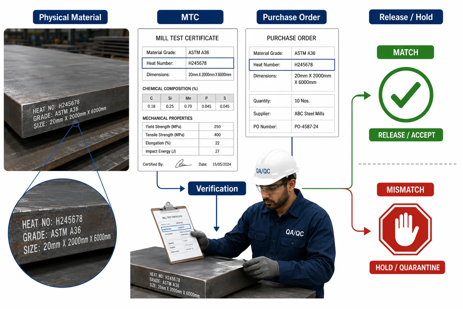
    The objective of incoming material verification is therefore to establish a controlled chain of evidence:

    Purchase requirement → Approved material specification → Supplier documentation → MTC → Material identification → Physical inspection → Traceability → Acceptance decision

    This process enables QA/QC teams to prevent unsuitable materials from entering fabrication and provides documented evidence that materials used in the completed project correspond to approved engineering requirements.

    Understanding incoming material verification

    Incoming material verification is the systematic process of confirming that delivered materials conform to the approved technical, contractual and quality requirements before they are accepted into controlled project stock or released for fabrication.

    The process normally considers four interconnected areas:

    • Documentary verification.

    • Physical verification.

    • Identification and traceability.

    • Technical acceptance.

    Documentary verification establishes what was ordered and what the supplier claims to have delivered. Physical verification establishes what has actually arrived. Traceability connects the physical item to its documentation. Technical acceptance determines whether the evidence demonstrates conformity with the project requirements.

    Why incoming material verification matters

    Incorrect material can create serious downstream consequences.

    Potential consequences include:

    • Structural weakness.

    • Reduced load-bearing capacity.

    • Premature component failure.

    • Incorrect welding procedures.

    • Incompatible heat-treatment requirements.

    • Corrosion problems.

    • Dimensional incompatibility.

    • Increased rework.

    • Production delays.

    • Non-conformance reports.

    • Customer rejection.

    • Loss of traceability.

    • Increased lifecycle costs.

    Once incorrect material has entered fabrication, identifying and correcting the problem can become considerably more difficult.

    Key definitions and concepts

    TermDefinitionQA/QC application
    Mill Test Certificate (MTC)Supplier/manufacturer document providing specified material and test informationUsed to verify grade, heat number and reported properties
    Material gradeDesignated material classification with defined requirementsConfirms suitability for the intended application
    Heat numberUnique identification associated with a specific material production heatProvides material traceability
    Batch numberIdentification assigned to a defined production or supply groupLinks materials to production and inspection records
    TraceabilityAbility to track material from source through useConnects material to certificates and installed components
    Purchase orderCommercial and technical order issued to the supplierDefines material requirements
    Material requisitionFormal request identifying required materialSupports procurement control
    Delivery noteSupplier document identifying delivered itemsReconciles delivered quantities and descriptions
    Physical verificationInspection of the actual delivered materialConfirms markings, dimensions and condition
    Chemical compositionElemental composition of the materialHelps verify material grade
    Mechanical propertiesMaterial behaviour characteristics such as strength and elongationConfirms specified performance
    Non-conformanceFailure to meet an approved requirementTriggers controlled investigation and disposition
    Material releaseFormal authorisation allowing material to proceedPrevents uncontrolled use
    QuarantineControlled segregation of material pending decisionPrevents accidental use of suspect material

    Relationship between the purchase order and MTC

    The purchase order establishes what the project requires. The MTC provides evidence of what the supplier states has been supplied.

    The QA/QC engineer should therefore compare the two.

    Relevant purchase-order information may include:

    • Material grade.

    • Material standard or specification.

    • Product form.

    • Thickness.

    • Diameter.

    • Length.

    • Quantity.

    • Surface condition.

    • Heat-treatment condition.

    • Testing requirements.

    • Certification requirements.

    • Special inspection requirements.

    The MTC should then be reviewed against these requirements.

    A material certificate should not be accepted simply because it contains a familiar material designation. The exact grade, product form, dimensions, testing requirements and identification must be relevant to the ordered material.

    Reviewing Mill Test Certificates

    MTC review is an important documentary control within incoming material inspection.

    Depending on the material and applicable requirements, an MTC may provide information concerning:

    • Manufacturer.

    • Material designation.

    • Product description.

    • Heat number.

    • Batch or lot number.

    • Dimensions.

    • Chemical composition.

    • Tensile strength.

    • Yield strength.

    • Elongation.

    • Impact properties where specified.

    • Hardness where specified.

    • Heat-treatment condition.

    • Test results.

    • Applicable material standard.

    • Certificate number.

    • Authorisation or certification details.

    The precise information depends on the material, specification and certification requirements.

    MTC review principles

    A professional review should establish:

    • Does the certificate correspond to the supplier?

    • Does the material grade match the order?

    • Does the heat number match the physical material?

    • Do dimensions correspond with the delivery?

    • Are reported properties within required limits?

    • Are required tests included?

    • Is the material condition correct?

    • Is the certificate complete?

    • Is the documentation traceable?

    • Are there unexplained discrepancies?

    Physical material identification

    Documentary evidence must be reconciled with the actual material.

    Physical identification may include:

    • Heat number.

    • Grade marking.

    • Manufacturer identification.

    • Product identification.

    • Batch number.

    • Size marking.

    • Diameter.

    • Thickness.

    • Length.

    • Colour coding where controlled.

    • Tags or labels.

    The exact identification method depends on the material and project requirements.

    Why physical marking matters

    Consider a delivery containing ten steel plates.

    The supplier provides one MTC covering a particular heat number.

    If the plates are not physically identified, the project team may be unable to demonstrate which plates correspond to that MTC after the materials are moved, cut or distributed.

    Traceability can therefore be lost even when the original documentation was correct.

    Physical inspection of incoming materials

    Physical inspection should assess both conformity and condition.

    The receiving inspection may include:

    • Quantity verification.

    • Product identification.

    • Dimensional measurement.

    • Surface inspection.

    • Marking verification.

    • Evidence of damage.

    • Corrosion assessment.

    • Deformation assessment.

    • Packaging condition.

    • Traceability marking.

    The objective is to establish whether the delivered material is suitable for controlled acceptance and whether its condition corresponds with project expectations.

    Dimensional verification

    Dimensional checks confirm that physical material dimensions correspond with the order and applicable requirements.

    Depending on the product, this may include:

    • Plate thickness.

    • Plate length.

    • Plate width.

    • Pipe outside diameter.

    • Pipe wall thickness.

    • Bar diameter.

    • Section dimensions.

    • Component length.

    • Flatness.

    • Straightness.

    Dimensional verification should use appropriate measuring equipment and controlled methods.

    Example

    A purchase order requires steel plate with a specified thickness.

    The delivery documentation identifies the correct grade, but physical inspection finds that some plates have a thickness outside the applicable requirement.

    The correct response is not to accept the material based solely on the MTC.

    The physical discrepancy requires investigation.

    Surface condition inspection

    Surface condition can influence fabrication and service performance.

    Inspection may identify:

    • Corrosion.

    • Pitting.

    • Laminations where externally detectable.

    • Cracks.

    • Mechanical damage.

    • Excessive scale.

    • Deformation.

    • Surface contamination.

    Visual inspection does not replace specialist non-destructive examination where such examination is required, but it provides an important initial quality control.

    Chemical composition verification

    The chemical composition reported on an MTC can support material-grade verification.

    Depending on the material, relevant elements may include:

    • Carbon.

    • Manganese.

    • Silicon.

    • Chromium.

    • Nickel.

    • Molybdenum.

    • Copper.

    • Other specified alloying elements.

    The QA/QC team should compare reported values against the applicable material requirements.

    Where project requirements call for independent verification, additional material identification testing may be appropriate.

    Mechanical property verification

    Mechanical properties reported on the MTC may include:

    • Yield strength.

    • Tensile strength.

    • Elongation.

    • Impact properties.

    • Hardness.

    The reported results should be compared with the required acceptance criteria.

    For example, if a specified material requires a minimum yield strength, the reported result must demonstrate compliance with the applicable requirement.

    Interpreting test results

    The engineer should distinguish between:

    • Required minimum values.

    • Required maximum values.

    • Reported results.

    • Test temperature where applicable.

    • Test direction where relevant.

    • Product-specific requirements.

    A numerical value cannot be interpreted correctly without its associated requirement and test conditions.

    Heat-number traceability

    Heat-number traceability is particularly important for steel and other manufactured metals.

    The heat number creates a link between:

    Material → Manufacturer → Production heat → Test results → Delivery → Project use

    Maintaining this link allows the project team to identify material history later.

    This becomes valuable when:

    • A material non-conformance is discovered.

    • A supplier issue is identified.

    • A component fails.

    • A customer requests traceability evidence.

    • A material recall or investigation occurs.

    Traceability throughout fabrication

    Traceability should not stop at receiving inspection.

    After acceptance, material identification should remain controlled during:

    • Storage.

    • Cutting.

    • Forming.

    • Machining.

    • Welding.

    • Assembly.

    • Installation.

    For example, if a large steel plate is cut into several components, the project may need a controlled method for transferring the relevant identification to the cut pieces.

    Without this control, the original MTC may no longer be reliably associated with the finished components.

    Incoming material verification workflow

    Stage 1: Review approved requirements

    Before receiving materials, the QA/QC team should understand:

    • Purchase-order requirements.

    • Approved drawings.

    • Material specifications.

    • Technical requisitions.

    • Inspection and test requirements.

    • Approved supplier information.

    Stage 2: Receive delivery documentation

    Collect:

    • Delivery note.

    • Packing list.

    • MTCs.

    • Relevant inspection documentation.

    • Supplier declarations where required.

    Stage 3: Reconcile documentation

    Compare:

    • Material grade.

    • Quantity.

    • Product form.

    • Dimensions.

    • Heat number.

    • Batch information.

    Stage 4: Inspect physical material

    Verify:

    • Markings.

    • Dimensions.

    • Surface condition.

    • Quantity.

    • Physical condition.

    Stage 5: Verify traceability

    Establish the relationship between:

    • Physical item.

    • Heat number.

    • MTC.

    • Purchase order.

    • Delivery.

    Stage 6: Review test results

    Assess:

    • Chemical composition.

    • Tensile strength.

    • Yield strength.

    • Elongation.

    • Hardness.

    • Impact testing where specified.

    Stage 7: Determine conformity

    Classify the material as:

    • Conforming.

    • Pending clarification.

    • Suspect.

    • Non-conforming.

    Stage 8: Control disposition

    Where material is acceptable:

    • Release it for controlled use.

    Where material is uncertain:

    • Place it on hold or quarantine.

    Where material is non-conforming:

    • Raise the required quality documentation and follow the approved disposition process.

    Material receiving inspection checklist

    A structured receiving inspection may address:

    • Purchase order reference.

    • Supplier name.

    • Delivery reference.

    • Material description.

    • Material grade.

    • Quantity.

    • Dimensions.

    • Heat number.

    • Batch number.

    • MTC reference.

    • Surface condition.

    • Physical marking.

    • Required tests.

    • Actual test results.

    • Traceability status.

    • Inspection result.

    • Acceptance status.

    The checklist should support traceability rather than become a purely administrative document.

    Comparing MTC information with physical material
    Material Verification Decision Flow

    One of the most important QA/QC controls is direct reconciliation.

    For example:

    MTC:

    • Grade: Approved steel grade.

    • Heat number: H24578.

    • Thickness: 20 mm.

    • Length: Specified length.

    Physical material:

    • Grade marking: Matching.

    • Heat number: H24578.

    • Thickness: Verified.

    • Dimensions: Verified.

    This provides a stronger basis for acceptance than documentation review alone.

    Example of an MTC discrepancy

    Suppose the MTC states:

    Heat number: H51240

    The physical plate is marked:

    Heat number: H51204

    The difference may appear minor, but it is significant because traceability cannot be assumed.

    The material should be controlled while the discrepancy is investigated.

    Potential explanations may include:

    • Marking error.

    • Documentation error.

    • Material mix-up.

    • Transcription error.

    • Incorrect certificate.

    The correct approach is controlled verification rather than assumption.

    Example of dimensional discrepancy

    A delivery order specifies a particular plate thickness.

    The MTC supports the correct material grade, but physical measurement identifies some plates below the specified thickness.

    The QA/QC engineer should:

    • Record the actual measurements.

    • Confirm measurement method.

    • Check instrument suitability.

    • Identify affected material.

    • Review the applicable tolerance.

    • Determine conformity.

    • Segregate suspect material if necessary.

    • Raise a non-conformance where required.

    Example of wrong material grade

    A supplier delivers a material with a grade different from the approved purchase requirement.

    Even if the alternative material appears stronger, the material should not automatically be accepted.

    Substitution may affect:

    • Design assumptions.

    • Welding procedure.

    • Heat treatment.

    • Corrosion performance.

    • Fatigue behaviour.

    • Certification.

    • Traceability.

    • Customer approval.

    Any substitution should therefore follow the project’s approved engineering and quality-control process.

    Quarantine and segregation

    Materials with unresolved discrepancies should be physically controlled.

    Quarantine may involve:

    • Dedicated storage area.

    • Clear identification.

    • Hold tags.

    • Restricted system status.

    • Controlled access.

    • Non-conformance reference.

    The objective is to prevent unintended use.

    Why segregation matters

    Consider a fabrication workshop where accepted and unverified materials are stored together.

    An operator may unknowingly select a suspect plate for fabrication.

    The quality problem then becomes much harder to control because the original material identity may be lost after cutting.

    Material release

    Material release should be based on documented evidence.

    A release decision may consider:

    • Correct material grade.

    • Acceptable dimensions.

    • Acceptable condition.

    • Valid MTC.

    • Matching heat number.

    • Satisfactory test results.

    • Complete traceability.

    • Approved inspection status.

    Only after these conditions are satisfied should material be released according to the project’s controlled procedure.

    Role of QA/QC personnel

    The QA/QC professional is responsible for ensuring that incoming material verification is objective, traceable and properly documented.

    Typical responsibilities include:

    • Reviewing purchase requirements.

    • Checking supplier documentation.

    • Inspecting material identification.

    • Verifying dimensions.

    • Reviewing MTCs.

    • Confirming traceability.

    • Recording inspection findings.

    • Identifying discrepancies.

    • Controlling non-conforming materials.

    • Supporting material release decisions.

    • Maintaining quality records.

    The QA/QC role should remain independent enough to prevent production pressure from overriding conformity requirements.

    Role of engineering personnel

    Engineering personnel may become involved where:

    • Material substitution is proposed.

    • Technical equivalence must be assessed.

    • Material properties differ from the specified requirements.

    • A concession is requested.

    • Service conditions are unusual.

    • The discrepancy could affect structural integrity.

    The QA/QC team identifies and controls the issue; the appropriate engineering authority determines technical suitability where engineering judgement is required.

    Role of procurement personnel

    Procurement helps maintain control by ensuring:

    • Correct material specifications are communicated.

    • Approved suppliers are used.

    • Required documentation is requested.

    • Purchase orders accurately state requirements.

    • Supplier deviations are controlled.

    Incoming inspection is therefore part of an integrated quality process rather than an isolated warehouse activity.

    Role of stores and warehouse personnel

    Stores personnel should support:

    • Material identification.

    • Controlled storage.

    • Segregation.

    • Traceability.

    • Preservation.

    • Movement records.

    A material can have perfect documentation but still lose traceability if warehouse controls are inadequate.

    Data integrity in material verification

    Quality records should be:

    • Accurate.

    • Legible.

    • Traceable.

    • Complete.

    • Timely.

    • Secure.

    • Controlled against unauthorised alteration.

    Important information should not rely solely on informal notes or verbal communication.

    Electronic quality systems can help maintain:

    • MTC records.

    • Inspection status.

    • Heat numbers.

    • Purchase-order references.

    • Material location.

    • Non-conformance status.

    • Release status.

    Material identification after cutting

    Cutting can create a major traceability risk.

    For example, one plate with a single heat number may be divided into twenty components.

    The original identification must be transferred according to an approved traceability method so that each component can still be connected to the original material record.

    This is particularly important for:

    • Pressure-related components.

    • Structural components.

    • Safety-critical components.

    • Welded assemblies.

    • Regulated equipment.

    Verification of supplier documentation

    MTCs should be reviewed for completeness and consistency.

    The QA/QC engineer should consider:

    • Supplier identity.

    • Certificate reference.

    • Material designation.

    • Heat number.

    • Test results.

    • Product description.

    • Dimensions.

    • Applicable requirements.

    • Authorisation.

    • Traceability.

    Any inconsistency should be investigated before acceptance.

    Common MTC review errors

    Checking only the material grade

    A correct grade does not prove that the physical material corresponds to the certificate.

    Ignoring heat numbers

    Without heat-number reconciliation, traceability can be compromised.

    Accepting photocopies without appropriate control

    The project’s document-control requirements should determine whether copies or electronic certificates are acceptable.

    Ignoring dimensions

    A material can have the correct grade but incorrect thickness or diameter.

    Ignoring material condition

    Heat treatment and delivery condition may affect performance.

    Treating certificates as proof of physical condition

    An MTC does not replace physical receiving inspection.

    Physical verification tools

    Depending on the material and project requirements, receiving inspection may use:

    • Vernier callipers.

    • Micrometers.

    • Steel rules.

    • Measuring tapes.

    • Thickness gauges.

    • Hardness testers.

    • Visual inspection equipment.

    • Identification verification systems.

    Measurement equipment should be appropriate for the required accuracy and maintained according to the applicable quality system.

    Measurement control

    Before dimensional verification, the inspector should consider:

    • Equipment suitability.

    • Calibration status where applicable.

    • Measurement resolution.

    • Measurement method.

    • Environmental conditions where relevant.

    • Measurement location.

    • Acceptance tolerance.

    A measurement result without a suitable measurement method may not provide reliable evidence.

    Key benefits of effective material verification

    A controlled incoming material verification system provides:

    • Prevention of incorrect material use.

    • Improved structural integrity.

    • Stronger traceability.

    • Reduced fabrication rework.

    • Reduced quality escapes.

    • Better supplier control.

    • Improved documentation.

    • Stronger audit readiness.

    • Better lifecycle traceability.

    • Reduced project risk.

    • Improved customer confidence.

    • More reliable engineering decisions.

    Practical example: structural steel delivery

    A fabrication project orders structural steel sections for a heavy mechanical support frame.

    The receiving team obtains:

    • Delivery note.

    • Purchase order.

    • MTCs.

    • Material identification records.

    The team first verifies the ordered grade and dimensions.

    Physical inspection confirms:

    • Section dimensions.

    • Heat markings.

    • Surface condition.

    • Quantity.

    The heat numbers are then reconciled against the MTCs.

    One bundle contains sections with an identification number that does not correspond to the certificate.

    The bundle is segregated pending clarification.

    The remainder of the material with verified traceability is released.

    This prevents a documentation discrepancy from becoming an uncontrolled fabrication issue.

    Practical example: pipe material verification

    A project receives metallic pipe for a mechanical system.

    The MTC identifies:

    • Correct grade.

    • Correct heat number.

    • Chemical composition.

    • Tensile properties.

    • Yield properties.

    Physical inspection additionally verifies:

    • Outside diameter.

    • Wall thickness.

    • Length.

    • Surface condition.

    • Markings.

    One group has the correct grade but an incorrect wall thickness.

    The material is not released simply because the MTC is satisfactory.

    The physical discrepancy is recorded and controlled.

    This demonstrates the essential relationship between documentary and physical verification.

    Practical example: fastener verification

    A heavy mechanical assembly requires specified high-strength fasteners.

    The receiving inspection verifies:

    • Grade.

    • Size.

    • Manufacturer identification.

    • Batch information.

    • Certificate documentation.

    • Surface condition.

    The QA/QC team identifies a mixed container containing fasteners from two different batches.

    Because batch traceability cannot initially be established, the mixed material is segregated until its identity and certification can be reconciled.

    This prevents uncontrolled mixing of potentially different material or property conditions.

    Practical example: material substitution

    A supplier proposes an alternative steel grade because the specified grade is temporarily unavailable.

    The alternative grade has a higher nominal tensile strength.

    The QA/QC engineer should not approve the substitution based solely on this fact.

    The assessment should consider:

    • Yield strength.

    • Ductility.

    • Toughness.

    • Weldability.

    • Heat-treatment condition.

    • Corrosion behaviour.

    • Design assumptions.

    • Applicable project requirements.

    The substitution should be referred through the approved technical review and change-control process.

    Handling non-conforming material

    When incoming material does not meet requirements, the response should be controlled.

    A typical process is:

    1. Identify the discrepancy.

    2. Record the finding.

    3. Mark or identify affected material.

    4. Segregate where necessary.

    5. Raise the appropriate non-conformance documentation.

    6. Determine the technical issue.

    7. Obtain required engineering or client review.

    8. Establish disposition.

    9. Record the decision.

    10. Update material status.

    Possible dispositions may include:

    • Return to supplier.

    • Replacement.

    • Rework where technically possible.

    • Approved concession.

    • Further testing.

    • Reclassification where formally authorised.

    • Rejection.

    The decision should be based on approved procedures and technical requirements.

    Supplier performance monitoring

    Incoming material verification can generate useful supplier-quality data.

    Relevant indicators may include:

    • MTC discrepancy rate.

    • Material rejection rate.

    • Dimensional non-conformity rate.

    • Traceability failures.

    • Documentation completeness.

    • Delivery conformity.

    • Recurring supplier defects.

    This information can support supplier evaluation and continual improvement.

    Material verification records

    A complete material record may contain:

    • Purchase order.

    • Material requisition.

    • Delivery note.

    • MTC.

    • Receiving inspection report.

    • Dimensional inspection results.

    • Non-conformance report if applicable.

    • Release documentation.

    • Storage location.

    • Traceability records.

    These records provide an auditable evidence chain.

    Case study: Incorrect heat-number traceability

    Project background

    A heavy mechanical fabrication project receives 200 tonnes of structural steel plate.

    The supplier provides MTCs for three production heats.

    During receiving inspection, the QA/QC inspector verifies:

    • Material grade.

    • Plate dimensions.

    • Quantity.

    • Surface condition.

    • Heat markings.

    Most plates match their certificates.

    However, several plates have markings that cannot be reconciled with the supplied MTC documentation.

    Initial response

    The QA/QC team:

    • Records the affected plates.

    • Places them on controlled hold.

    • Separates them from released material.

    • Reviews the delivery records.

    • Requests clarification from the supplier.

    The team does not permit the material to enter fabrication while traceability remains unresolved.

    Supplier investigation

    The supplier identifies a marking transcription error in part of the delivery documentation and provides controlled supporting evidence.

    The project team verifies that the physical material can be reliably reconciled with the correct production heat and supporting test records.

    Final decision

    The affected material is released only after the traceability evidence is satisfactorily restored.

    Lessons from the case

    The case demonstrates that:

    • MTC review must be linked to physical material.

    • Heat numbers are essential traceability controls.

    • Documentation discrepancies require controlled investigation.

    • Material should not be released solely on verbal assurance.

    • Segregation prevents accidental use.

    • Quality records provide evidence for the final decision.

    Conclusion

    Physical material verification and MTC review provide a critical control point between procurement and mechanical fabrication. The process ensures that materials entering a project correspond with the approved structural design orders, technical specifications and quality requirements. Effective verification combines documentary review with physical inspection, dimensional checks, identification confirmation, material-property assessment and traceability control. An MTC provides valuable evidence, but it cannot independently prove that the physical material delivered to the project is the material described on the certificate.

    A robust QA/QC system therefore establishes an unbroken relationship between the purchase requirement, supplier documentation, MTC, heat or batch identification, physical material and final project use. Any discrepancy involving grade, dimensions, condition, certification or traceability should be controlled and investigated before material is released. Quarantine, non-conformance management and documented disposition are important safeguards against accidental use of unsuitable materials.

    When these controls are applied consistently, organisations can prevent incorrect material selection, reduce fabrication rework, improve structural integrity, strengthen supplier quality management and maintain reliable project traceability. For heavy mechanical and structural engineering projects, the combination of MTC verification, physical inspection and controlled material identification provides an essential evidence base for confident material acceptance and long-term mechanical reliability.

    3. Analyse how different manufacturing processes, like heat treatment or welding, change the internal structure and strength of mechanical components

    Manufacturing processes can significantly alter the internal structure, mechanical properties, dimensional stability and long-term reliability of mechanical components. A material supplied with a particular chemical composition does not necessarily retain identical properties throughout every stage of manufacturing. Processes such as heat treatment, welding, forging, rolling, machining and forming can modify grain structure, phase distribution, residual stress, hardness, strength, toughness and ductility. For mechanical QA/QC, understanding these changes is essential because the final component must be assessed in its actual manufactured condition rather than solely against the properties of the original raw material.

    Heat treatment and welding are particularly important because both expose materials to controlled or localised thermal cycles. Heat treatment intentionally changes the microstructure to obtain a desired combination of strength, hardness, toughness and ductility. Welding, by contrast, creates highly localised heating and cooling that can produce different microstructural zones within the same component. These include the weld metal, heat-affected zone and unaffected parent material. The resulting differences can influence hardness, residual stress, distortion, fatigue behaviour and susceptibility to cracking.

    A competent mechanical QA/QC professional must therefore understand the relationship between manufacturing process, thermal history, microstructure and final performance. The objective is not simply to confirm that a process was completed, but to determine whether the resulting component satisfies the required engineering properties and quality criteria. This requires the controlled use of procedures, inspection, testing, traceability and engineering evaluation.

    Understanding the relationship between manufacturing and material structure

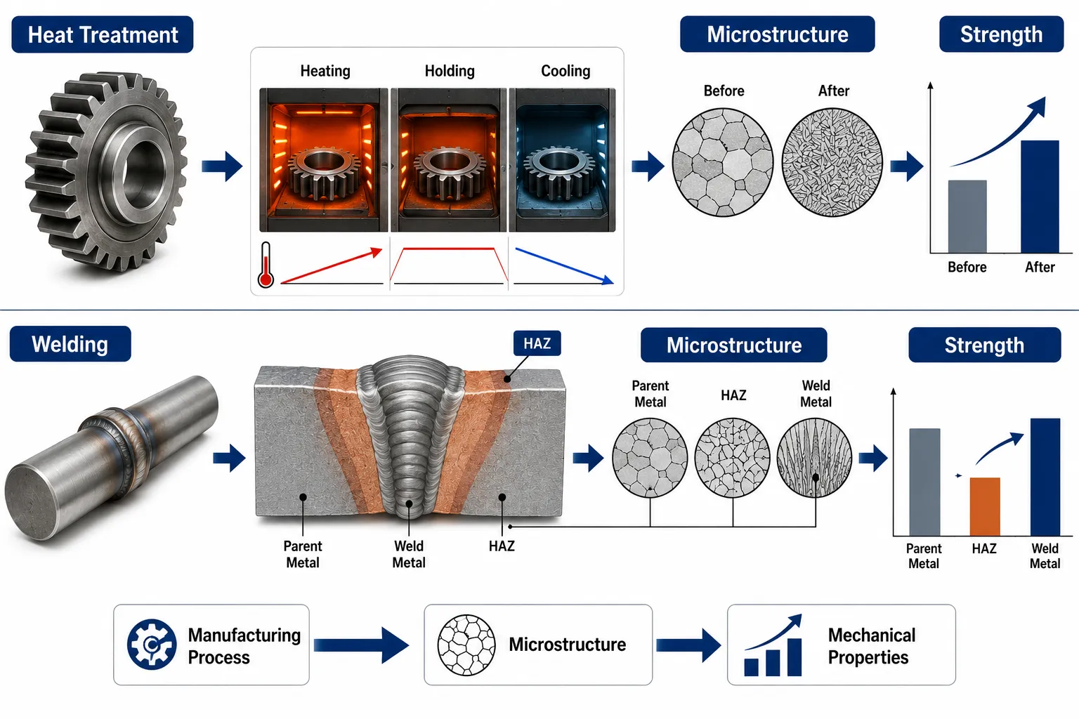
    Heat Treatment and Welding Infographic

    Metals are composed of microscopic grains and phases whose arrangement influences their mechanical behaviour. Manufacturing processes can change the size, shape, distribution and properties of these structures.

    The principal relationships can be represented as:

    Manufacturing process → Thermal/mechanical history → Microstructural change → Property change → Component performance

    For example, a steel component may initially have moderate strength and high ductility. Through controlled heat treatment, its microstructure can be changed to increase hardness and strength. However, if the treatment is poorly controlled, excessive hardness or inadequate toughness may result.

    Similarly, welding can create a strong joint when properly controlled, but inappropriate heat input, cooling rate or material preparation may produce undesirable microstructures, residual stresses or defects.

    Important factors include:

    • Heating temperature.

    • Heating rate.

    • Holding time.

    • Cooling rate.

    • Material chemistry.

    • Initial microstructure.

    • Section thickness.

    • Heat input.

    • Welding process.

    • Post-weld treatment.

    • Mechanical deformation.

    • Residual stress.

    • Environmental conditions.

    Key concepts and definitions

    ConceptDefinitionQA/QC significance
    MicrostructureInternal arrangement of grains and phases within a materialInfluences strength, hardness, ductility and toughness
    GrainIndividual crystalline region within a metalGrain characteristics influence mechanical behaviour
    PhaseDistinct structural form within an alloyPhase distribution affects material properties
    Heat treatmentControlled heating and cooling used to modify material propertiesProduces specified strength, hardness and toughness
    AnnealingHeating and controlled cooling used to soften or modify structureCan improve ductility and reduce residual stress
    NormalisingHeating followed by controlled cooling, commonly in air for steelsRefines structure and can improve uniformity
    QuenchingRapid cooling from an elevated temperatureCan increase hardness and strength
    TemperingControlled reheating after hardeningReduces excessive brittleness and adjusts properties
    HardeningTreatment intended to increase hardness and strengthUseful for wear-resistant components
    WeldingJoining process involving localised heating, with or without pressure/fillerCreates thermal and microstructural changes
    Heat-affected zone (HAZ)Parent material affected by welding heat without being meltedCan experience significant property changes
    Weld metalMaterial that has melted and solidified during weldingIts properties depend on process and filler conditions
    Residual stressInternal stress remaining after manufacturing loads or thermal cyclesCan influence distortion, fatigue and cracking
    Grain growthIncrease in grain size caused by excessive thermal exposureMay reduce toughness in some materials
    Cooling rateRate at which material temperature decreasesStrongly influences resulting microstructure
    Heat inputThermal energy introduced during a welding operationInfluences weld and HAZ characteristics
    Post-weld heat treatmentControlled thermal treatment after weldingCan modify residual stress and mechanical properties

    Why microstructure matters in mechanical engineering

    Microstructure provides a link between material chemistry and practical component performance. Two components manufactured from the same nominal alloy can exhibit different mechanical properties if they experience different thermal histories or manufacturing processes.

    Microstructural characteristics can influence:

    • Tensile strength.

    • Yield strength.

    • Hardness.

    • Ductility.

    • Toughness.

    • Fatigue resistance.

    • Wear resistance.

    • Corrosion behaviour.

    • Fracture behaviour.

    • Dimensional stability.

    This means that material identification alone is insufficient when assessing manufactured components.

    For example, two steel shafts may both be manufactured from the same nominal grade, but one may have been properly heat-treated while the other has experienced uncontrolled heating. Their hardness, strength and fatigue behaviour may differ considerably.

    Heat treatment and its engineering purpose

    Heat treatment is a controlled manufacturing process used to alter the internal structure of a metal or alloy.

    The process normally involves:

    1. Heating the material.

    2. Holding it at a specified temperature.

    3. Cooling it under controlled conditions.

    The exact thermal cycle depends on:

    • Material composition.

    • Component geometry.

    • Required properties.

    • Manufacturing specification.

    • Section thickness.

    • Desired microstructure.

    Heat treatment can be used to:

    • Increase hardness.

    • Increase strength.

    • Improve toughness.

    • Improve ductility.

    • Refine grain structure.

    • Reduce residual stress.

    • Improve wear resistance.

    • Improve dimensional stability.

    However, every benefit must be balanced against potential disadvantages.

    Annealing

    Annealing generally involves heating a material to an appropriate temperature followed by controlled cooling.

    It can be used to:

    • Reduce hardness.

    • Increase ductility.

    • Relieve certain residual stresses.

    • Improve machinability.

    • Modify microstructure.

    • Improve structural uniformity.

    For a heavily machined component, annealing may be useful where excessive hardness would make subsequent machining difficult.

    QA/QC considerations for annealing

    Quality control may verify:

    • Correct material grade.

    • Approved heat-treatment procedure.

    • Furnace temperature.

    • Holding time.

    • Cooling method.

    • Component identification.

    • Hardness.

    • Required mechanical properties.

    • Heat-treatment records.

    Normalising

    Normalising is commonly applied to steels and involves heating to an appropriate elevated temperature followed by cooling, often in air under controlled conditions.

    The process can:

    • Refine grain structure.

    • Improve microstructural uniformity.

    • Modify strength and hardness.

    • Improve mechanical consistency.

    Normalising can be useful for components where manufacturing history has produced an undesirable or inconsistent structure.

    QA/QC controls

    The inspection team may verify:

    • Material identification.

    • Treatment temperature.

    • Holding period.

    • Cooling conditions.

    • Furnace records.

    • Hardness results.

    • Test results.

    Quenching

    Quenching involves rapid cooling from an elevated temperature.

    The cooling medium may vary according to the material and process, with possibilities including:

    • Water.

    • Oil.

    • Polymer solutions.

    • Other controlled media.

    Rapid cooling can produce harder microstructures and substantially increase strength.

    However, rapid cooling can also create:

    • Residual stresses.

    • Distortion.

    • Cracking risk.

    • Excessive hardness.

    • Reduced ductility.

    Therefore, quenching should be followed by appropriate controls and, where specified, tempering.

    Tempering

    Tempering is commonly performed after hardening.

    The purpose is to adjust the balance between:

    • Hardness.

    • Strength.

    • Toughness.

    • Ductility.

    A hardened component may possess high hardness but insufficient toughness. Tempering can modify the microstructure to produce a more useful combination of properties.

    This illustrates a key engineering principle:

    Maximum hardness is not necessarily maximum component reliability.

    A gear, shaft or pin may require a carefully controlled balance between surface hardness and resistance to cracking or impact.

    Hardening and surface treatments

    Some mechanical components require high surface hardness while retaining a tougher core.

    Examples include:

    • Gears.

    • Shafts.

    • Pins.

    • Rollers.

    • Wear components.

    Surface-oriented treatments can produce:

    • Increased wear resistance.

    • Improved contact performance.

    • Greater surface hardness.

    The engineering objective is often to create a functional combination of:

    Hard surface + Tough supporting material

    This can improve service performance compared with producing the entire component at extremely high hardness.

    Effect of cooling rate on microstructure

    Cooling rate is one of the most important factors in thermal processing.

    A slow cooling rate may produce a different microstructure from rapid cooling.

    The resulting effects can influence:

    • Hardness.

    • Strength.

    • Toughness.

    • Ductility.

    • Residual stress.

    • Cracking susceptibility.

    Therefore, two otherwise identical components can have different properties if their cooling conditions differ.

    Practical implication

    A QA/QC inspector should not only ask:

    “Was the component heat-treated?”

    The more useful questions are:

    • Was the correct treatment used?

    • Was the required temperature achieved?

    • Was the holding period appropriate?

    • Was cooling properly controlled?

    • Was the component traceable?

    • Were required post-treatment tests completed?

    Grain structure and grain size

    Grain structure is an important factor in understanding material behaviour.

    Manufacturing processes can alter:

    • Grain size.

    • Grain orientation.

    • Grain distribution.

    • Phase distribution.

    Processes such as forging and rolling can produce directional structures, while excessive heating can promote grain growth.

    In many engineering situations, uncontrolled grain growth can adversely affect properties such as toughness.

    Therefore, temperature control is essential when processing metallic components.

    Welding and microstructural change

    Welding creates a highly localised thermal cycle.

    A typical welded joint can be considered as three important regions:

    • Weld metal.

    • Heat-affected zone.

    • Parent material.

    These regions may have different microstructures and therefore different mechanical properties.

    The weld metal melts and subsequently solidifies.

    The heat-affected zone does not melt but experiences sufficient heat to change its microstructure.

    The parent material outside the HAZ remains comparatively unaffected by the welding thermal cycle.

    This makes the welded component a metallurgically non-uniform system.

    The weld metal

    Weld metal forms from molten material that solidifies during welding.

    Its characteristics depend on:

    • Filler material.

    • Parent material.

    • Welding process.

    • Heat input.

    • Cooling rate.

    • Shielding conditions.

    • Welding parameters.

    The final properties of weld metal must meet the relevant requirements for the application.

    Potential concerns include:

    • Porosity.

    • Slag inclusions.

    • Lack of fusion.

    • Cracking.

    • Incorrect weld profile.

    • Inadequate penetration.

    These may affect mechanical performance even where the parent material itself is fully compliant.

    The heat-affected zone

    The heat-affected zone is particularly important because it may experience significant microstructural transformation without actually melting.

    The degree of change depends on:

    • Peak temperature.

    • Time at elevated temperature.

    • Cooling rate.

    • Material chemistry.

    • Section thickness.

    • Welding heat input.

    Potential consequences include:

    • Increased hardness.

    • Reduced toughness.

    • Grain growth.

    • Residual stress.

    • Hydrogen-assisted cracking susceptibility in appropriate materials.

    • Localised changes in mechanical behaviour.

    For this reason, welding QA/QC should consider the HAZ rather than concentrating exclusively on the visible weld bead.

    Welding heat input

    Heat input describes the amount of thermal energy introduced during welding.

    Higher heat input can influence:

    • Cooling rate.

    • HAZ width.

    • Grain growth.

    • Distortion.

    • Residual stress.

    • Weld microstructure.

    Lower heat input can produce different effects and may create other risks if insufficient fusion or penetration occurs.

    The correct welding parameters therefore need to be established through approved procedures and controlled during production.

    Preheating before welding

    Preheating may be required for certain materials and thicknesses.

    Its purposes can include:

    • Controlling cooling rate.

    • Reducing thermal gradients.

    • Reducing cracking susceptibility.

    • Supporting weld quality.

    The requirement depends on the material, thickness, welding procedure and applicable technical requirements.

    QA/QC controls may verify:

    • Required preheat temperature.

    • Measurement method.

    • Location of measurement.

    • Timing.

    • Recording of results.

    Interpass temperature

    During multi-pass welding, interpass temperature control is important because repeated thermal cycles can influence the final microstructure.

    Excessive interpass temperatures can contribute to:

    • Excessive heat accumulation.

    • Unwanted microstructural changes.

    • Grain growth.

    Insufficient control may also affect weld quality and cooling behaviour.

    Therefore, the approved welding procedure should define appropriate controls.

    Post-weld heat treatment

    Post-weld heat treatment may be specified for particular applications and materials.

    It can be used to:

    • Modify residual stress.

    • Alter hardness.

    • Improve certain mechanical characteristics.

    • Reduce susceptibility to particular failure mechanisms.

    QA/QC verification may involve:

    • Temperature records.

    • Heating rate.

    • Holding time.

    • Cooling rate.

    • Component identification.

    • Hardness testing.

    • Documentation review.

    Residual stresses

    Residual stresses are internal stresses remaining after manufacturing.

    They may arise from:

    • Welding.

    • Quenching.

    • Uneven cooling.

    • Forming.

    • Machining.

    • Grinding.

    Residual stresses can influence:

    • Distortion.

    • Fatigue performance.

    • Crack initiation.

    • Dimensional stability.

    • Stress corrosion behaviour in susceptible systems.

    Therefore, manufacturing control must consider not only immediate dimensional conformity but also internal stress conditions that could influence service performance.

    Distortion caused by manufacturing

    Thermal processes can produce uneven expansion and contraction.

    This is particularly relevant to:

    • Welded frames.

    • Large fabricated structures.

    • Thin plates.

    • Long shafts.

    • Machined components.

    Potential consequences include:

    • Misalignment.

    • Incorrect dimensions.

    • Assembly difficulties.

    • Uneven loading.

    • Increased machining requirements.

    QA/QC controls may therefore include:

    • Pre-fabrication dimensional checks.

    • Intermediate inspection.

    • Final dimensional inspection.

    • Alignment checks.

    • Corrective-action records.

    Manufacturing processes beyond heat treatment and welding

    Although heat treatment and welding are central to this assessment, other manufacturing processes can also modify material structure.

    Forging

    Forging subjects material to controlled plastic deformation.

    Potential benefits include:

    • Grain refinement.

    • Improved structural integrity.

    • Directional grain flow.

    • Improved mechanical properties.

    Forging is widely associated with components such as:

    • Shafts.

    • Crankshafts.

    • Connecting components.

    • Heavy-duty fittings.

    QA/QC may assess:

    • Forging temperature.

    • Reduction.

    • Material traceability.

    • Dimensional conformity.

    • Surface condition.

    • Heat treatment.

    Rolling

    Rolling changes the shape and thickness of material through controlled deformation.

    It can influence:

    • Grain orientation.

    • Mechanical anisotropy.

    • Thickness.

    • Surface characteristics.

    The resulting material condition may affect component behaviour in different directions.

    Cold working

    Cold working introduces plastic deformation below relevant recrystallisation temperatures.

    It can increase:

    • Strength.

    • Hardness.

    But it may also reduce:

    • Ductility.

    This illustrates another important relationship between manufacturing and mechanical properties.

    Machining and residual stress

    Machining removes material and can influence the surface and near-surface condition.

    Factors such as:

    • Cutting speed.

    • Feed rate.

    • Tool condition.

    • Cutting temperature.

    • Machining depth.

    can influence surface integrity.

    Potential effects include:

    • Residual stresses.

    • Surface roughness.

    • Local heating.

    • Dimensional changes.

    • Surface damage.

    For precision components, these factors may influence fatigue and wear performance.

    Manufacturing process and property balance

    The engineer should consider the desired combination of properties rather than maximising one characteristic.

    For example:

    Manufacturing approachPotential property effectPotential QA/QC concern
    AnnealingIncreased ductility, reduced hardnessIncorrect thermal cycle
    NormalisingRefined and more uniform structureInadequate treatment
    QuenchingIncreased hardness and strengthCracking or distortion
    TemperingImproved strength-toughness balanceIncorrect temperature or time
    WeldingLocalised structural changesHAZ and weld defects
    ForgingRefined grain flowIncomplete processing
    Cold workingIncreased strength and hardnessReduced ductility
    MachiningImproved geometrySurface damage or residual stress

    Process qualification and QA/QC

    Manufacturing processes that influence mechanical properties should be controlled through documented procedures.

    Important controls may include:

    • Approved manufacturing procedure.

    • Qualified personnel.

    • Controlled equipment.

    • Defined process parameters.

    • Material traceability.

    • Inspection points.

    • Testing requirements.

    • Calibration.

    • Records.

    • Acceptance criteria.

    The objective is to make the manufacturing process repeatable and demonstrably capable of producing conforming components.

    Heat-treatment quality control process

    Step 1: Confirm material identity

    Verify:

    • Material grade.

    • Heat number.

    • Component identification.

    • Required treatment.

    Step 2: Review approved procedure

    Confirm:

    • Heating temperature.

    • Holding time.

    • Heating rate.

    • Cooling method.

    • Required atmosphere where applicable.

    Step 3: Control the thermal cycle

    Record:

    • Actual temperature.

    • Time.

    • Furnace identification.

    • Load identification.

    • Cooling condition.

    Step 4: Conduct post-treatment inspection

    Depending on requirements:

    • Hardness.

    • Dimensional inspection.

    • Mechanical testing.

    • Visual examination.

    Step 5: Review records

    Confirm that the treatment was completed correctly and can be traced to the component.

    Welding quality control process

    A controlled welding process may involve:

    1. Confirming material identification.

    2. Reviewing the approved welding procedure.

    3. Confirming qualified personnel.

    4. Checking joint preparation.

    5. Verifying consumables.

    6. Controlling preheat.

    7. Monitoring welding parameters.

    8. Controlling interpass temperature.

    9. Inspecting weld appearance.

    10. Conducting required NDT.

    11. Applying post-weld treatment where specified.

    12. Recording results.

    Testing after manufacturing

    Manufacturing-induced changes may require verification through testing.

    Potential methods include:

    • Tensile testing.

    • Hardness testing.

    • Impact testing.

    • Metallographic examination.

    • Visual inspection.

    • Ultrasonic testing.

    • Magnetic particle testing.

    • Dye penetrant testing.

    • Radiographic testing.

    The appropriate method depends on:

    • Component type.

    • Material.

    • Manufacturing process.

    • Failure risk.

    • Project requirements.

    Practical example: heat-treated gear

    A heavy industrial gearbox requires gears with high surface hardness and adequate core toughness.

    The manufacturing process involves controlled heat treatment.

    The QA/QC team reviews:

    • Material certificate.

    • Heat-treatment procedure.

    • Furnace records.

    • Treatment temperature.

    • Holding time.

    • Cooling process.

    • Surface hardness.

    • Dimensional condition.

    Engineering assessment

    If the hardness is below the required range, wear performance may be compromised.

    If hardness is significantly excessive, the team must also consider whether excessive brittleness or cracking risk could result.

    The correct objective is therefore the specified property range rather than the maximum possible hardness.

    Practical example: welded pressure-related component

    A heavy fabricated component is produced using multiple weld passes.

    The parent material has the correct grade and certification.

    During welding, the team controls:

    • Welding procedure.

    • Preheat.

    • Interpass temperature.

    • Consumables.

    • Welding parameters.

    After welding, required inspection identifies a local area with elevated hardness.

    Technical significance

    The elevated hardness may indicate an undesirable thermal or metallurgical condition.

    The QA/QC team should not simply accept the result because the weld visually appears satisfactory.

    The appropriate response is to:

    • Record the finding.

    • Confirm measurement validity.

    • Compare with requirements.

    • Investigate potential causes.

    • Obtain engineering review where required.

    • Determine appropriate disposition.

    Practical example: shaft after machining

    A forged and heat-treated shaft is subsequently machined.

    Final dimensional inspection confirms that all dimensions are within tolerance.

    However, an engineering review identifies unexpected surface cracking.

    This demonstrates why dimensional conformity alone is insufficient.

    The investigation should consider:

    • Material condition.

    • Heat treatment.

    • Machining parameters.

    • Surface integrity.

    • Residual stress.

    • Previous manufacturing operations.

    Case Study: Heat treatment and welding interaction

    Background

    A heavy mechanical frame incorporates high-strength steel components joined through welding. Several components have also undergone controlled heat treatment before fabrication.

    During final inspection, one welded region demonstrates unexpected hardness values and local distortion.

    Initial findings

    The material documentation confirms:

    • Correct grade.

    • Correct heat number.

    • Acceptable material properties.

    The welding records show:

    • Approved welding procedure.

    • Controlled consumables.

    • Recorded welding parameters.

    However, the inspection results indicate that the final component does not behave uniformly across all regions.

    Investigation

    The QA/QC and engineering teams review:

    • Parent material condition.

    • Heat-treatment records.

    • Welding heat input.

    • Preheat records.

    • Interpass temperature.

    • Cooling conditions.

    • HAZ hardness.

    • Distortion measurements.

    The investigation identifies that the thermal history during fabrication altered the local microstructure and contributed to the observed property variation.

    Corrective approach

    The team develops a controlled corrective action based on:

    • Manufacturing sequence.

    • Thermal controls.

    • Welding parameters.

    • Post-weld requirements.

    • Additional inspection.

    Key lesson

    The case demonstrates that final component performance depends on the combined manufacturing history rather than a single material certificate.

    The relevant relationship is:

    Original material properties + Heat treatment + Welding + Cooling + Residual stress + Final inspection = Actual manufactured condition

    Common manufacturing-related QA/QC failures

    Assuming raw-material properties remain unchanged

    Manufacturing processes can substantially modify the final condition.

    Checking only the weld appearance

    A visually acceptable weld may still have internal or metallurgical problems.

    Ignoring the HAZ

    The HAZ can experience significant property changes even though it does not melt.

    Treating hardness as the only acceptance criterion

    Hardness must be interpreted alongside strength, toughness and ductility requirements.

    Failing to control thermal cycles

    Temperature and cooling history can significantly influence microstructure.

    Losing traceability

    If the component cannot be linked to its manufacturing records, investigation becomes difficult.

    Ignoring residual stresses

    Residual stresses can contribute to distortion and service degradation.

    Key benefits of controlling manufacturing-induced changes

    Effective process control can provide:

    • Consistent mechanical properties.

    • Improved component reliability.

    • Reduced premature failures.

    • Reduced welding defects.

    • Improved dimensional stability.

    • Better fatigue performance.

    • Improved wear resistance.

    • Stronger traceability.

    • Reduced rework.

    • Better process repeatability.

    • Improved inspection confidence.

    • More reliable service-life predictions.

    Strategic QA/QC approach

    A mature mechanical QA/QC system should integrate material verification with manufacturing-process control.

    The process can be viewed as:

    Material verification

    Manufacturing-process control

    Thermal and mechanical history control

    Inspection and testing

    Final property verification

    Component acceptance

    This integrated approach is stronger than treating material inspection, welding inspection and final inspection as unrelated activities.

    Critical engineering evaluation

    When assessing a manufactured component, the engineer should ask:

    • What was the original material?

    • What manufacturing processes were applied?

    • What thermal cycles occurred?

    • What mechanical deformation occurred?

    • How could the microstructure have changed?

    • How could those changes affect strength?

    • Could hardness have increased excessively?

    • Could ductility have decreased?

    • Could residual stresses have developed?

    • Could distortion have occurred?

    • What inspection evidence confirms the final condition?

    • Is the final component suitable for its intended service?

    These questions help move QA/QC from simple inspection towards engineering-based quality evaluation.

    Conclusion

    Manufacturing processes can fundamentally change the internal structure and mechanical properties of metallic components. Heat treatment intentionally modifies microstructure to achieve controlled combinations of strength, hardness, toughness and ductility, while welding creates localised thermal cycles that can produce distinct conditions within the weld metal, heat-affected zone and parent material. Processes such as quenching, tempering, normalising, annealing, forging, cold working and machining can similarly alter grain structure, residual stress, hardness, strength and dimensional stability.

    For mechanical QA/QC, the critical principle is that the final component must be assessed according to its manufactured condition, not simply its original material designation. Material certificates establish the starting condition, but process records, thermal-cycle controls, welding documentation, inspection results, hardness testing, dimensional verification and other appropriate examinations provide evidence of how manufacturing has affected the final component.

    A robust quality approach therefore connects material identity, manufacturing history, microstructural behaviour and final performance. By controlling heat treatment, welding parameters, cooling conditions, residual stresses, traceability and post-process inspection, engineering teams can reduce defects, improve reliability, prevent premature failure and produce mechanical components with predictable and repeatable performance. This integrated understanding of materials and manufacturing processes is essential for effective mechanical engineering QA/QC and long-term component reliability.

    4. Document precise material testing results to clear or reject raw materials before they enter the main production line

    Precise documentation of material testing results is a critical element of mechanical engineering QA/QC because it provides objective evidence for deciding whether incoming raw materials are suitable for production. Before steel plates, bars, pipes, forgings, castings, fasteners or other engineering materials are released to a manufacturing line, their identity, condition and required material properties must be verified against approved technical requirements. Testing may generate information relating to tensile strength, yield strength, elongation, hardness, impact resistance, chemical composition, dimensions or other specified characteristics. However, test results only become effective quality evidence when they are accurately recorded, traceable to the specific material and evaluated against clearly defined acceptance criteria.

    The fundamental principle is that material should not enter controlled production simply because it has arrived or because a supplier has provided a certificate. The receiving QA/QC process must establish whether the physical material corresponds with its documentation and whether the available inspection and testing evidence demonstrates conformity. Where results meet the applicable requirements, the material can be formally cleared or released in accordance with the approved procedure. Where results are outside requirements, incomplete, inconsistent or unreliable, the material should be placed on controlled hold or rejected according to the applicable non-conformance process. This prevents defective or unsuitable material from becoming embedded in subsequent manufacturing activities.

    Purpose of material testing documentation

    Material testing documentation creates an auditable evidence trail connecting the incoming material to its technical requirements and final acceptance decision.

    A properly controlled record should allow an independent reviewer to determine:

    • What material was tested.

    • Which batch or heat it came from.

    • Which test was performed.

    • When the test was performed.

    • Which test method was used.

    • What equipment was used.

    • Who performed or witnessed the test.

    • What result was obtained.

    • What acceptance criterion applied.

    • Whether the result complied.

    • Who reviewed the result.

    • What final material disposition was authorised.

    This information supports both immediate quality decisions and future investigations.

    For example, if a mechanical component fails several months after production, the organisation may need to establish whether the original material complied with its specified properties. Without accurate testing records, such an investigation becomes unnecessarily difficult.

    Key definitions and concepts

    TermDefinitionQA/QC relevance
    Material test resultRecorded outcome obtained from a defined material testProvides evidence of material conformity
    Acceptance criterionDefined requirement against which a result is evaluatedDetermines pass or fail status
    Material releaseControlled authorisation allowing material to enter productionPrevents uncontrolled material use
    Material holdTemporary restriction preventing material use pending verificationControls uncertain material
    RejectionFormal determination that material does not satisfy requirementsPrevents non-conforming material entering production
    Heat numberIdentification associated with a particular material production heatMaintains traceability
    Batch numberIdentification of a defined group of materialLinks material to testing and records
    Test methodControlled procedure used to obtain a measurementSupports consistency and validity
    Test specimenRepresentative portion prepared for testingProvides the physical basis for the test
    TraceabilityAbility to connect material to its source and recordsSupports verification and investigation
    Non-conformanceFailure to meet a specified requirementRequires controlled disposition
    VerificationProcess of confirming information or resultsSupports reliable acceptance decisions
    CalibrationComparison or adjustment of measuring equipment against a known referenceSupports measurement reliability
    Material statusControlled indication of whether material is accepted, held or rejectedPrevents accidental use
    Test recordDocumented evidence of testing and resultsProvides audit and decision evidence

    Why precise material testing results matter

    The accuracy and completeness of material test records influence several aspects of engineering quality.

    Effective records help:

    • Prevent unsuitable materials entering production.

    • Establish material conformity.

    • Maintain heat and batch traceability.

    • Support material release decisions.

    • Identify recurring supplier problems.

    • Demonstrate compliance with project requirements.

    • Support non-conformance investigations.

    • Provide evidence during audits.

    • Support failure investigations.

    • Improve supplier performance monitoring.

    • Reduce rework.

    • Protect production schedules.

    • Improve long-term component reliability.

    A poorly documented test result can create almost as much uncertainty as not performing the test.

    Material testing within the QA/QC lifecycle

    Material testing should be integrated into the incoming inspection workflow.

    A typical sequence is:

    Material received

    Identification and traceability verified

    Documentation reviewed

    Required testing confirmed

    Testing performed or results independently reviewed

    Results recorded

    Results compared with acceptance criteria

    QA/QC review

    Material released, held or rejected

    This sequence creates a controlled barrier between incoming materials and production.

    Identifying the material before testing

    Testing is meaningful only when the tested specimen can be reliably linked to the material being assessed.

    Before testing, verify:

    • Material description.

    • Material grade.

    • Heat number.

    • Batch number.

    • Supplier.

    • Purchase-order reference.

    • Delivery reference.

    • Product form.

    • Dimensions.

    • Material condition.

    If traceability is uncertain, testing results may not be sufficient to release the material.

    Example

    A tensile test produces an acceptable result, but the specimen cannot be reliably linked to the heat number of the delivered plates.

    The result should not automatically be used to release the entire delivery.

    The traceability issue must first be resolved.

    Establishing the required tests

    The QA/QC team should identify testing requirements from approved project information.

    Sources may include:

    • Purchase specifications.

    • Approved material specifications.

    • Technical requisitions.

    • Drawings.

    • Inspection and test plans.

    • Contract requirements.

    • Approved procedures.

    • Applicable engineering standards.

    • Supplier documentation requirements.

    The exact testing requirements depend on the material, application and project.

    Potential tests include:

    • Tensile testing.

    • Yield-strength assessment.

    • Elongation testing.

    • Hardness testing.

    • Impact testing.

    • Chemical composition analysis.

    • Dimensional verification.

    • Visual inspection.

    • Other specified material examinations.

    Tensile testing documentation

    Tensile testing can provide information about:

    • Yield strength.

    • Tensile strength.

    • Elongation.

    • Load-extension behaviour.

    A complete record should identify:

    • Material.

    • Heat or batch number.

    • Specimen identification.

    • Test method.

    • Test equipment.

    • Test date.

    • Test result.

    • Required acceptance range.

    • Result status.

    Interpreting tensile results

    The reported tensile strength should be compared with the applicable requirement rather than judged in isolation.

    For example:

    Required minimum tensile strength: 500 MPa
    Measured tensile strength: 535 MPa

    The result exceeds the stated minimum.

    However, the QA/QC review should also consider whether other required properties comply.

    A material can have acceptable tensile strength while failing another requirement such as elongation, impact performance or chemical composition.

    Yield strength documentation

    Yield strength is important where permanent deformation must be controlled.

    The record should capture:

    • Required value.

    • Measured value.

    • Test condition.

    • Specimen identification.

    • Material identification.

    • Acceptance status.

    Example

    If a specification requires a minimum yield strength of 355 MPa and the test result is 370 MPa, the result meets that particular criterion.

    However, the complete material release decision must still consider all other applicable requirements.

    Elongation and ductility

    Elongation provides information about material ductility.

    The record should identify:

    • Required minimum elongation.

    • Measured elongation.

    • Specimen information.

    • Test method.

    • Material traceability.

    A result that demonstrates insufficient ductility may indicate that the material does not meet the specified mechanical-property requirements even if tensile strength is satisfactory.

    Hardness testing

    Hardness testing is commonly used to assess resistance to indentation and can provide useful evidence about material condition.

    Common systems include:

    • Rockwell.

    • Brinell.

    • Vickers.

    Documentation should include:

    • Hardness method.

    • Test location.

    • Test result.

    • Material identification.

    • Acceptance range.

    • Equipment identification where required.

    • Inspector or tester.

    • Date.

    Importance of test location

    Hardness may vary across a component because of:

    • Heat treatment.

    • Surface treatment.

    • Manufacturing history.

    • Localised thermal exposure.

    Therefore, the test location should be controlled and recorded where location influences interpretation.

    Chemical composition results

    Chemical analysis can provide evidence that the material corresponds to the required grade.

    Depending on the material, the record may include concentrations of:

    • Carbon.

    • Manganese.

    • Silicon.

    • Chromium.

    • Nickel.

    • Molybdenum.

    • Other specified elements.

    The results should be compared with the relevant material requirements.

    Why chemical composition matters

    Incorrect chemical composition can influence:

    • Strength.

    • Hardness.

    • Corrosion resistance.

    • Weldability.

    • Toughness.

    • Heat-treatment response.

    Therefore, chemical verification can be an important part of material acceptance.

    Impact testing

    Where specified, impact testing provides information about material behaviour under sudden loading conditions.

    The record should include:

    • Test temperature.

    • Specimen identification.

    • Material traceability.

    • Test results.

    • Required acceptance criteria.

    Temperature is particularly important because some materials can exhibit different toughness behaviour under different conditions.

    Dimensional testing

    Material acceptance may also require dimensional verification.

    Measurements may include:

    • Thickness.

    • Diameter.

    • Length.

    • Width.

    • Wall thickness.

    • Flatness.

    • Straightness.

    The documentation should identify:

    • Measurement location.

    • Measurement result.

    • Required tolerance.

    • Measuring equipment where appropriate.

    • Inspector.

    • Material identification.

    Test equipment and measurement reliability

    A test result is only useful when the measurement process is reliable.

    QA/QC personnel should therefore consider:

    • Equipment suitability.

    • Calibration status where applicable.

    • Measurement range.

    • Resolution.

    • Test method.

    • Test environment.

    • Operator competence.

    A result obtained using unsuitable or uncontrolled equipment should not automatically be treated as valid evidence.

    Test specimen traceability

    Where destructive testing is performed, the specimen must remain linked to the material from which it was taken.

    The traceability chain may be:

    Material → Heat number → Specimen ID → Test record → Result → Acceptance decision

    If the specimen identification is lost, the result may no longer provide reliable evidence for the original material.

    Sampling considerations

    Testing every piece may not always be necessary or technically required.

    Where sampling is used, the QA/QC procedure should define:

    • Sample size.

    • Selection method.

    • Frequency.

    • Test location.

    • Acceptance criteria.

    • Treatment of failures.

    Sampling must be representative and controlled.

    Example

    A batch contains 500 components.

    If the approved inspection requirement specifies testing a defined sample, the QA/QC team should follow that sampling plan rather than selecting convenient components.

    A convenient sample may not adequately represent the batch.

    Recording raw test data

    Where appropriate, the original or raw data should be retained.

    Examples include:

    • Force readings.

    • Extension measurements.

    • Hardness readings.

    • Chemical analysis output.

    • Temperature records.

    • Dimensional measurements.

    Raw data can be valuable if a result is later challenged or investigated.

    Converting test results into acceptance decisions

    Material Testing Quality Control Workflow

    A QA/QC professional should distinguish between:

    Measurement

    and

    Decision

    The measurement provides evidence.

    The acceptance criterion provides the benchmark.

    The engineering or quality decision determines the material status.

    For example:

    PropertyRequirementResultStatus
    Tensile strength≥500 MPa535 MPaPass
    Yield strength≥355 MPa370 MPaPass
    Elongation≥20%23%Pass
    Hardness180–220 HB205 HBPass

    If all required criteria comply and traceability is confirmed, the material may be considered for release.

    Material clearance

    Material clearance is the controlled process of confirming that material can proceed into production.

    Before clearance, the QA/QC team should confirm:

    • Correct material.

    • Correct grade.

    • Correct dimensions.

    • Acceptable physical condition.

    • Complete documentation.

    • Valid test results.

    • Traceability.

    • Compliance with acceptance criteria.

    Clearance status

    A controlled status system may use:

    • Accepted.

    • Released.

    • Approved for production.

    • Hold.

    • Rejected.

    The exact terminology should follow the organisation’s quality system.

    Material rejection

    Rejection may be required where:

    • Test results fail acceptance criteria.

    • Material grade is incorrect.

    • Traceability is lost.

    • Physical dimensions are outside requirements.

    • Required documentation is missing.

    • Material condition is unacceptable.

    • Test results cannot be validated.

    • Supplier deviation is not approved.

    The rejection should be documented and controlled.

    Material hold

    Not every discrepancy immediately requires rejection.

    A material may be placed on hold when:

    • Documentation is incomplete.

    • A test result requires verification.

    • Traceability is unclear.

    • Additional testing is required.

    • Engineering review is pending.

    • Supplier clarification is required.

    The hold status prevents uncontrolled production use while allowing investigation.

    Non-conformance reporting

    Where material fails an approved requirement, a non-conformance record may be required.

    It should clearly describe:

    • Material identification.

    • Requirement.

    • Actual result.

    • Nature of deviation.

    • Evidence.

    • Affected quantity.

    • Immediate containment.

    • Proposed disposition.

    • Approval status.

    Example

    Requirement:

    Minimum yield strength = 355 MPa

    Actual result:

    Yield strength = 332 MPa

    The record should clearly show:

    • Material heat.

    • Test specimen.

    • Test result.

    • Applicable requirement.

    • Difference.

    • Quantity affected.

    • Material status.

    This provides a defensible quality record.

    Preventing non-conforming material from reaching production

    Physical and administrative controls should work together.

    Controls may include:

    • Quarantine areas.

    • Hold tags.

    • Electronic status controls.

    • Colour identification where formally controlled.

    • Restricted material locations.

    • Release documentation.

    • Production system status.

    The objective is simple:

    No material should enter controlled production unless its status is clearly established.

    Data integrity requirements

    Material test records should be:

    • Accurate.

    • Complete.

    • Legible.

    • Traceable.

    • Timely.

    • Protected from unauthorised alteration.

    • Consistent with source records.

    Important information should never be changed informally without an appropriate correction and approval process.

    Common documentation weaknesses

    • Missing heat number.

    • Incorrect material grade.

    • Transposed numerical results.

    • Missing units.

    • Unclear test method.

    • Missing acceptance criterion.

    • Unidentified specimen.

    • Unclear reviewer.

    • Uncontrolled corrections.

    These weaknesses can undermine an otherwise valid test.

    Units and numerical accuracy

    Engineering test results must be recorded with appropriate units.

    Examples include:

    • MPa.

    • N/mm².

    • HB.

    • HRC.

    • HV.

    • %.

    • mm.

    A numerical value without its unit may be ambiguous.

    For example:

    355

    does not provide sufficient engineering information.

    Whereas:

    Yield strength = 355 MPa

    provides meaningful information.

    Review and verification of test results

    A second-level review can help identify:

    • Calculation errors.

    • Transcription errors.

    • Incorrect units.

    • Incorrect acceptance criteria.

    • Inconsistent material identification.

    • Missing results.

    The reviewer should compare the test record with the original requirement and supporting documentation.

    Digital material testing records

    Modern QA/QC systems increasingly use electronic quality records.

    A digital system may link:

    • Purchase order.

    • Material certificate.

    • Heat number.

    • Inspection report.

    • Test result.

    • Non-conformance.

    • Release status.

    Advantages include:

    • Faster retrieval.

    • Improved traceability.

    • Reduced transcription.

    • Easier reporting.

    • Better auditability.

    • Improved data analysis.

    However, electronic systems still require appropriate access control, data validation and document control.

    Material testing workflow

    Stage 1: Identify material

    Confirm:

    • Grade.

    • Heat.

    • Batch.

    • Dimensions.

    • Supplier.

    Stage 2: Establish requirements

    Identify:

    • Required properties.

    • Required tests.

    • Acceptance limits.

    • Sampling requirements.

    Stage 3: Perform testing

    Ensure:

    • Correct procedure.

    • Suitable equipment.

    • Competent personnel.

    • Controlled specimen identification.

    Stage 4: Record results

    Capture:

    • Raw results.

    • Units.

    • Test conditions.

    • Equipment.

    • Date.

    • Inspector.

    Stage 5: Validate results

    Check:

    • Traceability.

    • Equipment status.

    • Test method.

    • Calculations.

    • Data completeness.

    Stage 6: Compare with criteria

    Determine:

    • Pass.

    • Fail.

    • Further investigation required.

    Stage 7: Determine material status

    Apply:

    • Release.

    • Hold.

    • Reject.

    Stage 8: Control records

    Store:

    • Test report.

    • Supporting documents.

    • MTC.

    • Inspection records.

    • Release or rejection record.

    Practical example: steel plate clearance

    A fabrication project receives a batch of structural steel plate.

    The QA/QC team verifies:

    • Material grade.

    • Heat number.

    • Plate thickness.

    • Surface condition.

    • MTC.

    Required testing includes tensile properties and chemical composition.

    The test results show:

    • Tensile strength: compliant.

    • Yield strength: compliant.

    • Elongation: compliant.

    • Chemical composition: compliant.

    The heat number on the physical plate matches the certificate.

    The material is therefore technically suitable for release, subject to completion of all applicable project checks.

    The release record identifies the material batch and references the supporting test documentation.

    Practical example: failed hardness test

    A batch of heat-treated mechanical components is received.

    The required hardness range is defined by the approved specification.

    Testing produces:

    • Component 1: compliant.

    • Component 2: compliant.

    • Component 3: above the specified maximum.

    The team should not simply average the values and release the batch.

    The abnormal result must be investigated according to the applicable sampling and acceptance requirements.

    Possible considerations include:

    • Test validity.

    • Test location.

    • Equipment status.

    • Heat-treatment variation.

    • Batch identification.

    The material remains controlled until the appropriate decision is reached.

    Practical example: incomplete test report

    A supplier provides an MTC showing tensile strength and yield strength but does not provide a required impact-test result.

    The correct response is not to assume that the impact test was satisfactory.

    The material should remain under controlled status while the missing evidence is obtained or the approved technical process determines the appropriate disposition.

    This illustrates an important principle:

    Missing evidence is not equivalent to conforming evidence.

    Practical example: incorrect specimen identification

    A tensile test report contains acceptable results, but the specimen number cannot be linked to a specific heat.

    The result cannot reliably establish conformity for the affected material until traceability is restored.

    The QA/QC team should:

    • Place the material on hold.

    • Investigate specimen identification.

    • Review test records.

    • Review sampling records.

    • Obtain supporting evidence.

    • Determine whether retesting is required.

    Case Study: Raw material acceptance decision

    Background

    A heavy mechanical fabrication project receives a batch of alloy steel bars for manufacturing high-load shafts.

    The purchase requirements specify:

    • Approved material grade.

    • Minimum yield strength.

    • Minimum tensile strength.

    • Minimum elongation.

    • Controlled hardness range.

    • Full traceability.

    Initial inspection

    The receiving team confirms:

    • Quantity.

    • Diameter.

    • Surface condition.

    • Grade marking.

    • Heat numbers.

    The MTCs are reviewed and appear complete.

    Testing

    QA/QC performs or reviews the required material tests.

    Results show:

    • Tensile strength: compliant.

    • Yield strength: compliant.

    • Elongation: compliant.

    • Hardness: one sample above the specified maximum.

    Investigation

    The team checks:

    • Test equipment.

    • Test location.

    • Specimen identification.

    • Heat-treatment records.

    • Sampling requirements.

    The test is confirmed valid.

    Decision

    Because the result exceeds the applicable acceptance criterion, the affected material is placed on controlled hold.

    The organisation follows the approved non-conformance and technical disposition process rather than releasing the material based on the other acceptable results.

    Lesson

    The case demonstrates why precise documentation matters.

    A single clearly recorded result can prevent potentially unsuitable material from entering production.

    Supplier quality improvement

    Material testing records can also support supplier performance management.

    Organisations can analyse:

    • Percentage of batches accepted first time.

    • Material rejection rate.

    • MTC discrepancies.

    • Failed test frequency.

    • Traceability failures.

    • Documentation errors.

    • Recurring material grades with problems.

    This information can help identify suppliers requiring corrective action or increased oversight.

    Key benefits of precise material test documentation

    A robust system provides:

    Quality benefits

    • Reliable material acceptance.

    • Reduced defective inputs.

    • Better traceability.

    • Improved conformity control.

    • Reduced production defects.

    Operational benefits

    • Fewer production interruptions.

    • Reduced rework.

    • Faster material release.

    • Better inventory control.

    • Improved planning.

    Engineering benefits

    • Stronger material evidence.

    • Better failure investigation.

    • Improved reliability assessment.

    • More defensible engineering decisions.

    Management benefits

    • Better supplier evaluation.

    • Stronger audit evidence.

    • Improved quality reporting.

    • More effective continual improvement.

    Common mistakes to avoid

    Recording results without acceptance criteria

    A result has limited meaning unless compared with the applicable requirement.

    Recording results without units

    This can create ambiguity.

    Releasing material based only on the MTC

    Physical material and documentation must be reconciled.

    Ignoring traceability

    An acceptable test result cannot reliably support material acceptance if the tested specimen cannot be linked to the material.

    Averaging failed results away

    Individual failures must be treated according to the approved acceptance and sampling procedure.

    Using uncontrolled spreadsheets

    Where electronic records are used, data integrity and version control should be maintained.

    Allowing production pressure to influence technical decisions

    Material status should be determined using objective quality evidence and approved procedures.

    Strategic QA/QC model for material release

    A strong material-release system can be represented as:

    Correct material identification

    Complete documentation

    Valid testing

    Accurate results

    Comparison against requirements

    Independent review

    Controlled status

    Release / Hold / Reject

    This model provides a clear decision pathway and reduces the possibility of unsuitable materials reaching production.

    Conclusion

    Precise documentation of material testing results is an essential control within mechanical engineering QA/QC. It transforms physical measurements and laboratory findings into reliable evidence that can support the controlled release, hold or rejection of raw materials. Effective documentation must establish a clear relationship between the material, heat or batch number, test specimen, test method, measured result, applicable acceptance criterion and final disposition. Without this traceability, even technically accurate test results may have limited value.

    The material acceptance process should therefore combine physical verification, documentation review, controlled testing, measurement reliability, data validation and technical assessment. Tensile strength, yield strength, elongation, hardness, impact properties, chemical composition and dimensional results should be evaluated against the specific requirements applicable to the material and project. Where results are compliant and traceability is confirmed, the material can be formally released. Where results are uncertain, incomplete or non-conforming, controlled hold, investigation, further testing or rejection should be applied according to the approved quality process.

    Ultimately, accurate material testing documentation prevents unsuitable raw materials from entering the production line and provides a reliable evidence base for mechanical component quality, structural integrity and long-term reliability. When integrated with material traceability, MTC verification, non-conformance management and supplier-quality monitoring, precise test records strengthen the entire QA/QC system and help ensure that only verified and conforming materials progress into manufacturing.