
Lesson no 3 : Develop strategies for project supervision, team coordination, and decision-making.
Introduction
Effective project supervision, team coordination and decision-making are essential to the successful delivery of mechanical engineering and QA/QC projects. Complex engineering projects involve multiple activities, technical disciplines, personnel, contractors, suppliers and quality requirements that must be managed in a structured and coordinated manner. Supervisors and project leaders therefore need the ability to plan work, allocate responsibilities, monitor progress, communicate expectations and make informed decisions when technical or operational challenges arise.
Project supervision involves guiding and monitoring engineering activities to ensure that work is completed safely, efficiently and in accordance with approved specifications, procedures, quality plans and project requirements. In a QA/QC mechanical environment, effective supervision helps ensure that inspection activities, testing, material control, manufacturing processes and installation work are properly coordinated. It also enables potential delays, technical problems and quality risks to be identified and addressed before they have a significant impact on the project.
Team coordination is equally important because mechanical projects often depend on close cooperation between engineers, QA/QC inspectors, technicians, production teams, contractors and project managers. Clear communication, defined roles and effective coordination help prevent duplicated work, misunderstandings and gaps in responsibility. A well-coordinated team can respond more effectively to changing project priorities while maintaining focus on safety, quality and delivery objectives.
Professional decision-making requires supervisors and project leaders to evaluate available information, consider technical and quality implications, assess risks and select appropriate actions. Decisions should be supported by reliable evidence, applicable standards, project requirements and professional judgement. Where problems or conflicts arise, a structured decision-making approach can help teams identify practical solutions while maintaining compliance and accountability.
This lesson develops the knowledge and professional understanding required to create effective strategies for supervising projects, coordinating diverse teams and making sound decisions in mechanical engineering and QA/QC environments. Learners will explore approaches to work planning, communication, responsibility allocation, performance monitoring, problem-solving, risk-based decision-making and stakeholder coordination.
By developing these competencies, Learners will be better prepared to support project delivery, maintain productive working relationships and respond effectively to technical and operational challenges. The lesson also emphasises the importance of leadership, evidence-based judgement and continuous monitoring in achieving project objectives while maintaining the required standards of safety, quality and professional practice.
1.Formulate a Clear Cross-Department Coordination Plan to Ensure Seamless Communication Between the QA/QC Team, Design Engineers, and Production Managers
Effective mechanical engineering projects depend on much more than the technical competence of individual departments. Quality assurance and quality control personnel, design engineers and production managers often work with different responsibilities, priorities and timescales. However, their activities are closely connected. A design decision can affect manufacturability, a production change can create a quality risk, and an inspection finding can require engineering clarification. Without a structured coordination plan, important information may be delayed, misunderstood or lost between departments.
A clear cross-department coordination plan establishes how relevant information will be shared, who is responsible for decisions, when meetings and reviews will take place, how technical issues will be escalated and how changes will be controlled. In a QA/QC mechanical environment, this structured approach supports compliance with approved specifications, drawings, inspection requirements, manufacturing procedures and project quality objectives.
The purpose is not simply to increase the number of meetings or emails. Effective coordination creates a controlled communication system that ensures the right information reaches the right people at the right time. It also provides traceability, accountability and a clear route for resolving technical or quality-related issues.
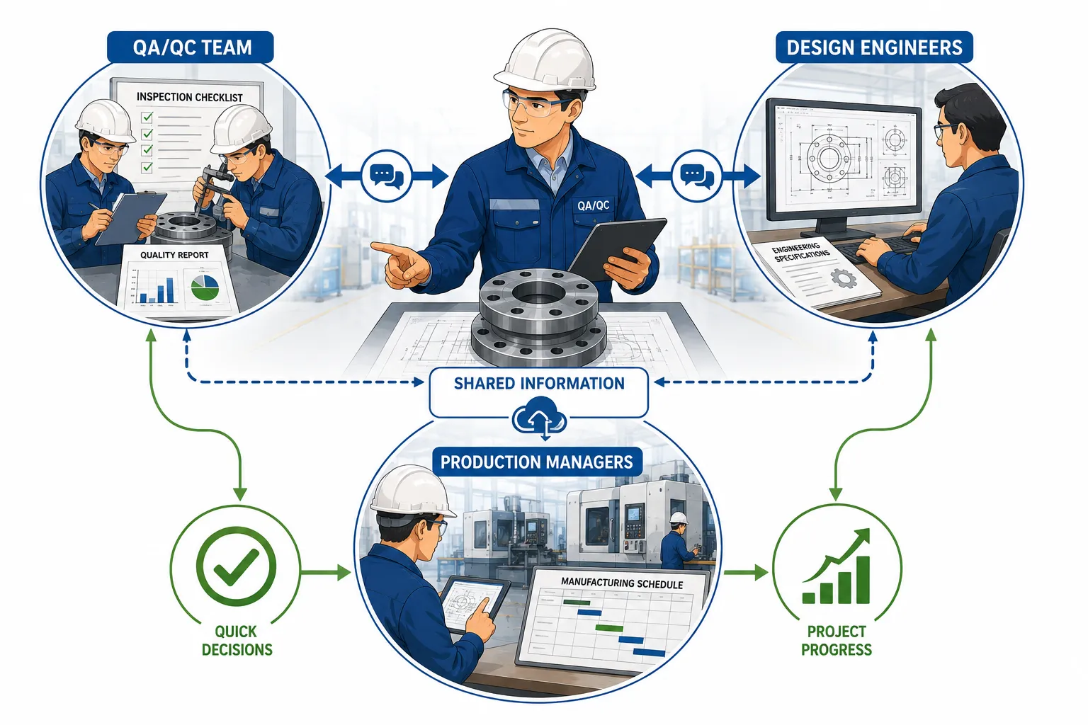
Understanding Cross-Department Coordination
Cross-department coordination is the organised management of communication, responsibilities and activities between different functional teams working towards common project objectives. In mechanical engineering projects, the coordination process commonly connects design, procurement, production, QA/QC, maintenance, project management and other relevant functions.
Each department contributes specialist knowledge. Design engineers define technical requirements and engineering solutions. Production managers organise manufacturing resources and control operational activities. QA/QC teams verify that materials, processes and completed work meet defined requirements.
For coordination to be effective, these functions must not operate as isolated groups. Information must move accurately between them, particularly when project conditions change or technical problems are identified.
Key coordination objectives include:
Establishing clear communication channels.
Defining departmental responsibilities.
Preventing conflicting instructions.
Sharing technical and quality information promptly.
Controlling engineering and production changes.
Resolving issues through an agreed escalation process.
Maintaining traceable records of important decisions.
Supporting project milestones and delivery requirements.
Reducing delays caused by misunderstandings.
Protecting product quality and compliance.
A successful coordination plan therefore combines people, processes, communication methods and controlled documentation.
Why Coordination Is Critical in QA/QC Mechanical Projects
Mechanical projects frequently involve interconnected activities. A change to a drawing may affect material requirements, machining dimensions, welding activities, inspection points or assembly procedures. If the production team receives incomplete or outdated information, work may proceed incorrectly. Similarly, if a QA/QC inspector identifies a non-conformance but the design team is not informed promptly, the technical issue may remain unresolved.
Poor communication can lead to significant operational and quality consequences.
Common consequences include:
Manufacturing to obsolete drawings.
Incorrect material selection.
Delayed inspection activities.
Rework and repair.
Unauthorised engineering deviations.
Conflicting instructions between departments.
Missed project milestones.
Increased production costs.
Repeated non-conformities.
Client dissatisfaction.
Delays in final acceptance.
A formal coordination plan reduces these risks by creating predictable communication routes and defined responsibilities.
The Relationship Between QA/QC, Design and Production
The three departments have different but complementary functions.
QA/QC Team
The QA/QC team focuses on ensuring that defined requirements are understood, implemented and verified. Its role may include reviewing inspection requirements, monitoring manufacturing activities, conducting inspections, managing non-conformities and maintaining quality records.
Key responsibilities may include:
Reviewing inspection and test requirements.
Verifying material traceability.
Monitoring critical manufacturing activities.
Raising and controlling non-conformity reports.
Reviewing inspection results.
Maintaining quality documentation.
Reporting quality risks and trends.
Confirming that corrective actions are implemented.
QA/QC personnel should communicate findings clearly and objectively. Their role is not only to identify defects but also to provide relevant evidence that supports technical decisions.
Design Engineers
Design engineers establish the technical requirements for the product or mechanical system. Their work may include drawings, specifications, calculations, material requirements and engineering decisions.
Their coordination responsibilities may include:
Issuing approved engineering information.
Responding to technical clarification requests.
Reviewing proposed deviations.
Assessing the effect of design changes.
Providing technical acceptance criteria.
Clarifying drawing or specification requirements.
Supporting root cause investigations where design factors are involved.
Design engineers must ensure that technical information is communicated in a controlled and understandable form.
Production Managers
Production managers coordinate manufacturing resources, personnel, equipment and schedules. They must ensure that work is performed using the correct approved information and processes.
Their responsibilities may include:
Planning production activities.
Allocating personnel and resources.
Confirming the availability of approved documents.
Reporting production constraints.
Coordinating corrective actions.
Managing manufacturing progress.
Communicating operational changes.
Supporting quality and inspection activities.
Production managers provide an important link between project requirements and practical workshop execution.
Key Definitions and Concepts
| Term | Definition | Importance in Cross-Department Coordination |
|---|---|---|
| Cross-department coordination | The structured management of activities and communication between different functional teams | Ensures departments work towards common project objectives |
| Communication plan | A documented approach defining what information is communicated, by whom, to whom and when | Reduces information gaps and misunderstandings |
| RACI matrix | A responsibility model identifying who is Responsible, Accountable, Consulted and Informed | Clarifies ownership and decision-making authority |
| Technical query | A formal request for clarification regarding engineering or technical requirements | Prevents assumptions and unauthorised interpretations |
| Non-conformance | A failure to meet a specified requirement | Requires controlled communication and resolution |
| Change control | A formal process for reviewing, approving and implementing changes | Prevents uncontrolled changes from affecting quality |
| Escalation | The process of referring an unresolved issue to an appropriate higher authority | Ensures critical issues receive timely attention |
| Interface | A point where responsibilities or information pass between departments | Requires clear coordination to prevent gaps |
| Project milestone | A significant planned stage or decision point within a project | Helps align departmental activities |
| Traceability | The ability to follow the history and status of information, materials or decisions | Supports accountability and audit readiness |
Establishing the Purpose and Scope of the Coordination Plan
Defining the Project Coordination Objectives
The first stage in formulating a coordination plan is to identify what the plan is expected to achieve. The objectives should reflect the size, complexity and risk profile of the mechanical project.
A coordination plan may aim to ensure that:
Design information is issued before production begins.
QA/QC requirements are incorporated into production planning.
Technical queries are answered through approved channels.
Inspection activities are coordinated with manufacturing stages.
Engineering changes are reviewed before implementation.
Non-conformities are communicated to relevant departments.
Corrective actions are tracked to completion.
Project milestones are visible to all relevant teams.
Critical risks are escalated promptly.
Clear objectives prevent the plan from becoming a general administrative document with no practical value.
Defining the Scope
The scope should identify the departments, activities and interfaces covered by the plan.
The scope may include:
Design and engineering.
QA/QC.
Production and manufacturing.
Procurement and material control.
Project management.
Maintenance, where relevant.
Contractors and subcontractors.
Client or third-party representatives where required.
The plan should also identify which types of information require formal communication.
Examples include:
Approved drawings.
Engineering specifications.
Inspection and test plans.
Material certificates.
Technical queries.
Non-conformance reports.
Change orders.
Deviation requests.
Inspection results.
Corrective action reports.
Production schedules.
Identifying Critical Communication Interfaces
Mapping the Flow of Information
Before defining communication methods, project leaders should understand how information currently moves between departments. A communication map can identify critical interfaces and possible weaknesses.
A simple flow may involve:
Design Requirements → Production Planning → Manufacturing Activity → QA/QC Verification → Technical Feedback → Corrective or Engineering Decision
However, real projects often involve multiple feedback loops. For example, QA/QC may identify an issue during production that requires input from both the production manager and the design engineer.
The coordination plan should identify:
Where information originates.
Who reviews the information.
Who receives the information.
Who has authority to make decisions.
How responses are recorded.
What happens if a response is delayed.
Identifying High-Risk Interfaces
Not every communication point carries the same level of risk. Particular attention should be given to activities where incorrect information could cause significant quality or safety problems.
High-risk interfaces may include:
Release of revised engineering drawings.
Approval of substitute materials.
Acceptance of manufacturing deviations.
Changes to critical dimensions.
Welding procedure requirements.
Heat treatment requirements.
Inspection hold points.
Non-conformance disposition decisions.
Final acceptance decisions.
These interfaces should have formal controls rather than relying only on informal verbal communication.
Creating Clear Roles and Responsibilities
Using a Responsibility Matrix
One of the most effective methods for improving coordination is the use of a responsibility matrix. A RACI approach can help define the involvement of each department.
RACI represents:
Responsible – performs the activity.
Accountable – has final ownership of the outcome.
Consulted – provides specialist input.
Informed – receives relevant information.
For example, a design change may require:
Design engineer: Responsible for technical review.
Engineering manager: Accountable for approval.
QA/QC manager: Consulted regarding quality implications.
Production manager: Consulted regarding manufacturability.
Production team: Informed after approval.
This structure reduces confusion about who has the authority to make decisions.
Avoiding Role Overlap and Gaps
Poor coordination often occurs when several people believe another department is responsible for an activity. The opposite problem occurs when multiple departments issue different instructions.
The coordination plan should clearly identify:
Decision owners.
Review responsibilities.
Approval authorities.
Communication recipients.
Escalation authorities.
Record-keeping responsibilities.
Clear accountability supports faster and more reliable project decisions.
Designing Effective Communication Channels
Formal Communication Channels
Important technical and quality information should normally be communicated through controlled channels.
Examples include:
Approved document management systems.
Formal technical queries.
Non-conformance reporting systems.
Controlled project correspondence.
Approved meeting minutes.
Change control records.
Inspection reports.
Corrective action registers.
Formal communication provides traceability and reduces dependence on memory.
Informal Communication
Informal communication remains valuable for daily coordination. Quick discussions between inspectors, engineers and production personnel can help resolve minor operational questions quickly.
However, informal communication should not replace formal approval when decisions affect:
Design requirements.
Quality acceptance criteria.
Manufacturing procedures.
Material requirements.
Inspection requirements.
Safety-critical conditions.
A useful principle is that informal discussion may identify or explore an issue, but significant decisions should be formally recorded and communicated.
Communication Methods Within the Plan
The plan should specify the most suitable method for each communication type.
Examples include:
Daily production meetings for immediate operational coordination.
Weekly coordination meetings for progress and interface issues.
Formal technical queries for engineering clarification.
Digital dashboards for project performance.
Controlled document systems for drawings and procedures.
Escalation notices for urgent quality risks.
Written meeting minutes for agreed actions.
The communication method should be appropriate to the urgency and importance of the information.
Establishing a Structured Meeting Strategy
Daily Coordination Meetings
Short daily meetings can be effective in active manufacturing environments. They should focus on immediate priorities rather than repeating long technical discussions.
Typical agenda points include:
Previous day’s completed work.
Current production priorities.
Planned inspections.
Outstanding quality issues.
Material availability concerns.
Technical queries requiring follow-up.
Safety or operational constraints.
Participants may include:
Production supervisor or manager.
QA/QC representative.
Relevant engineering representative.
Planning personnel where necessary.
Weekly Cross-Department Reviews
Weekly meetings can focus on broader project coordination.
The agenda may include:
Project progress against milestones.
Outstanding engineering issues.
Non-conformance trends.
Corrective action status.
Upcoming critical inspections.
Design changes.
Production constraints.
Resource requirements.
Key project risks.
Meeting minutes should clearly record:
Decisions made.
Actions required.
Responsible persons.
Target completion dates.
Escalation requirements.
Technical Review Meetings
Technical review meetings should be arranged when an issue requires specialist analysis.
Examples include:
A dimensional deviation.
Repeated manufacturing defects.
Material substitution requests.
Unexpected test results.
Conflicting specification requirements.
These meetings should focus on evidence and applicable requirements rather than personal opinions.
Developing a Controlled Technical Query Process
Purpose of Technical Queries
A technical query provides a formal mechanism for requesting clarification when project information is unclear or conflicting.
A clear process prevents production personnel from making unauthorised assumptions.
A technical query may be raised when:
A drawing contains unclear information.
Specifications appear to conflict.
A dimension cannot be practically achieved.
Material requirements are uncertain.
An inspection criterion requires clarification.
A production condition differs from the original design assumption.
Recommended Technical Query Process
A structured process may include the following steps:
Identify the technical issue.
Review available drawings and specifications.
Gather relevant evidence.
Prepare a clear technical query.
Submit the query to the authorised reviewer.
Record the response.
Assess the impact on production and quality.
Communicate the approved decision.
Update controlled documents where required.
Verify implementation.
A technical query should clearly describe the issue without attempting to conceal uncertainty or provide unsupported conclusions.
Integrating QA/QC Requirements into Production Planning
Early QA/QC Involvement
QA/QC should not become involved only after production has been completed. Early coordination enables inspection requirements to be incorporated into the manufacturing plan.
Early involvement supports:
Identification of critical inspection stages.
Planning of hold and witness points.
Availability of qualified inspectors.
Preparation of measuring equipment.
Review of material documentation.
Coordination of specialised testing.
Prevention of avoidable production delays.
Aligning Inspection with Production Milestones
The production manager and QA/QC team should jointly identify when inspections must occur.
The coordination process may include:
Reviewing the production schedule.
Identifying critical manufacturing stages.
Linking inspections to planned activities.
Confirming inspection resources.
Identifying required test equipment.
Communicating hold points.
Updating schedules when production priorities change.
This approach reduces the risk of completed work being inaccessible for required inspection.
Managing Engineering and Production Changes
The Importance of Change Control
Mechanical projects frequently experience changes caused by technical developments, client requirements, material availability or production constraints. Uncontrolled changes can create serious quality and compliance risks.
A coordination plan should establish that changes must not be implemented solely through verbal instruction.
Changes may involve:
Revised drawings.
Modified dimensions.
Material substitutions.
Process changes.
Inspection changes.
Manufacturing sequence changes.
Approved deviations.
Change Coordination Process
An effective process may include:
Identification of the proposed change.
Description of the reason for the change.
Assessment of technical impact.
Review of quality implications.
Review of production implications.
Formal approval by authorised personnel.
Revision of controlled documents.
Communication to affected teams.
Verification of implementation.
Maintenance of change records.
This process ensures that all relevant departments understand how the change affects their responsibilities.
Establishing an Effective Issue Escalation Process
When Issues Should Be Escalated
Some issues cannot be resolved at operational level. The coordination plan should define when escalation is required.
Escalation may be appropriate when:
A critical technical decision is delayed.
A non-conformance affects safety or functionality.
Departments disagree about interpretation.
Production is at risk of proceeding without approval.
A client requirement is unclear.
Repeated defects continue despite corrective actions.
A project milestone is seriously threatened.
Escalation Levels
A structured escalation system may include:
Level 1: Operational Resolution
Minor issues are addressed by supervisors and relevant technical personnel.
Level 2: Departmental Review
Issues requiring specialist input are reviewed by QA/QC managers, design leads or production managers.
Level 3: Project Management Decision
Significant project impacts are escalated to project leadership.
Level 4: Client or External Authority Review
Issues requiring external approval are referred through the authorised project process.
The purpose of escalation is not to assign blame. It is to ensure that issues receive decisions at the appropriate authority level.
Managing Non-Conformities Through Coordination
Cross-Department Response to Non-Conformities
A non-conformance may affect several departments. QA/QC may identify the issue, production may need to contain affected work, and design engineers may need to determine the technical disposition.
A coordinated response may include:
Immediate identification of affected items.
Containment of potentially non-conforming work.
Notification of relevant departments.
Collection of objective evidence.
Technical evaluation.
Root cause investigation where required.
Decision on correction or disposition.
Implementation of corrective action.
Verification of effectiveness.
Clear communication prevents the same issue from being handled differently by separate teams.
Avoiding Blame-Focused Communication
Quality problems should be discussed professionally. A blame-focused culture may discourage personnel from reporting problems.
Effective communication should focus on:
What happened.
What requirement was affected.
What evidence is available.
What immediate action is required.
What caused the issue.
How recurrence can be prevented.
This approach supports continuous improvement and stronger collaboration.
Practical Example: Coordination During a Manufacturing Issue
Consider a project involving the manufacture of a mechanical assembly. During inspection, the QA/QC inspector identifies that a machined component does not meet the required dimensional tolerance.
The coordination process could proceed as follows:
The QA/QC inspector records the dimensional evidence.
The affected component is identified and controlled.
The production manager is informed immediately.
Production of similar components is reviewed.
The design engineer receives a formal request for technical evaluation.
The engineering team confirms whether the deviation affects function.
The production team investigates the machining process.
A corrective action is agreed.
Any approved decision is formally documented.
QA/QC verifies the corrective action before normal production continues.
The key benefit is that no single department attempts to make a decision outside its authority or technical competence.
Monitoring the Effectiveness of the Coordination Plan
Establishing Performance Indicators
A coordination plan should be reviewed to determine whether it is producing the intended results.
Useful indicators may include:
Number of overdue technical queries.
Average response time for engineering clarification.
Number of repeated non-conformities.
Percentage of actions completed by target date.
Number of production delays caused by information issues.
Number of uncontrolled document revisions identified.
Frequency of communication-related defects.
Percentage of planned coordination meetings completed.
These indicators should be used to identify improvement opportunities rather than simply measure departmental performance.
Reviewing Communication Failures
When a significant problem occurs, the project team should determine whether communication contributed to the issue.
Review questions may include:
Was the correct information available?
Was the information current?
Did the correct department receive it?
Was the communication method appropriate?
Were responsibilities clear?
Was a decision delayed?
Was escalation required but not used?
Were changes formally communicated?
The results can be used to strengthen the coordination process.
Key Benefits of a Clear Cross-Department Coordination Plan
A well-designed plan provides significant benefits for mechanical engineering projects.
Quality Benefits
Reduces the risk of manufacturing from incorrect information.
Improves coordination of inspection activities.
Supports timely resolution of non-conformities.
Strengthens change control.
Reduces repeated quality problems.
Project Management Benefits
Improves visibility of project priorities.
Supports milestone planning.
Reduces avoidable delays.
Clarifies responsibilities.
Improves action tracking.
Technical Benefits
Provides a formal route for engineering clarification.
Improves the quality of technical decisions.
Ensures specialist knowledge is available when required.
Reduces unauthorised interpretations.
Supports evidence-based problem-solving.
Team Benefits
Improves collaboration between departments.
Reduces confusion and duplicated effort.
Creates clearer expectations.
Encourages timely reporting of issues.
Supports a more professional working environment.
Practical Steps for Developing the Coordination Plan
A project leader can formulate the plan through a structured process.
Step 1: Identify the Departments
Determine which teams influence project quality, production and engineering decisions.
Step 2: Map Critical Interfaces
Identify where information and responsibility move between departments.
Step 3: Define Communication Requirements
Specify what information must be shared and when.
Step 4: Assign Responsibilities
Use a responsibility matrix to clarify ownership and authority.
Step 5: Select Communication Channels
Choose appropriate formal and informal communication methods.
Step 6: Establish Meeting Arrangements
Define the frequency, purpose and participants of coordination meetings.
Step 7: Create Technical Query Procedures
Provide a controlled route for requesting clarification.
Step 8: Establish Change Control
Ensure significant changes are reviewed and approved before implementation.
Step 9: Define Escalation Routes
Specify how urgent or unresolved issues will be referred to appropriate authorities.
Step 10: Monitor Performance
Review communication effectiveness using relevant evidence and performance indicators.
Step 11: Improve the Plan
Update the coordination approach when project conditions, risks or organisational requirements change.
Professional Practice Considerations
Effective coordination requires professional behaviour as well as formal procedures. Technical personnel should communicate clearly, respect departmental expertise and avoid making decisions beyond their authority.
Good professional practice includes:
Communicating factual information accurately.
Using controlled documents.
Avoiding unsupported assumptions.
Recording important decisions.
Respecting defined approval authorities.
Raising concerns promptly.
Listening to operational and technical perspectives.
Maintaining professional communication during disagreements.
Focusing on project requirements rather than personal preferences.
Following escalation procedures when necessary.
A coordination plan is most effective when personnel understand both the process and the reasons for using it.
Conclusion
Formulating a clear cross-department coordination plan is essential for ensuring seamless communication between QA/QC teams, design engineers and production managers. Mechanical engineering projects depend on the accurate exchange of technical, quality and operational information, and failures at departmental interfaces can result in defects, delays, rework and uncontrolled changes.
An effective coordination plan establishes clear objectives, communication channels, responsibilities, meeting arrangements, technical query procedures, change control processes and escalation routes. It also integrates QA/QC requirements into production planning and ensures that design, production and quality decisions are based on relevant evidence and appropriate authority.
For Learners working in mechanical QA/QC and project supervision roles, the key principle is that coordination should be systematic rather than dependent on informal relationships or individual memory. The right information must be communicated to the right people, through the correct channel, at the appropriate time.
By applying structured coordination strategies, project teams can improve collaboration, resolve technical issues more efficiently, maintain stronger control of quality requirements and support successful achievement of overall project milestones.
2. Establish a Structured Project Supervision Framework to Monitor the Progress of Mechanical Inspections Across Workshop Zones or Construction Sites
Effective project supervision is essential for ensuring that mechanical inspection activities are planned, coordinated, monitored and completed in accordance with project requirements. Mechanical engineering projects may involve multiple workshop zones, fabrication areas, installation locations, construction fronts or geographically separated work areas. Each location may contain different equipment, personnel, materials, processes and inspection requirements. Without a structured supervision framework, inspection activities can become inconsistent, delayed or poorly documented.
A structured project supervision framework provides a systematic method for monitoring inspection progress from the beginning of the project through to final completion and handover. It defines how inspection work is planned, assigned, tracked, reviewed and escalated. It also establishes clear responsibilities for supervisors, inspectors, QA/QC personnel, production teams and project managers.
In a workshop environment, supervision may involve monitoring fabrication, machining, welding, assembly, dimensional inspection, material identification and testing activities. On a construction site, the same framework may need to coordinate inspections across installation areas, piping systems, structural components, mechanical equipment and commissioning activities. Although the physical environment may differ, the fundamental principle remains the same: inspection activities must be performed at the correct stage, by competent personnel, against approved requirements and within the required project timeframe.
The purpose of supervision is not simply to check whether inspectors are present at work locations. Professional supervision involves evaluating progress against plans, identifying obstacles, verifying the completion of inspection activities, reviewing outstanding issues and ensuring that quality risks receive appropriate attention.
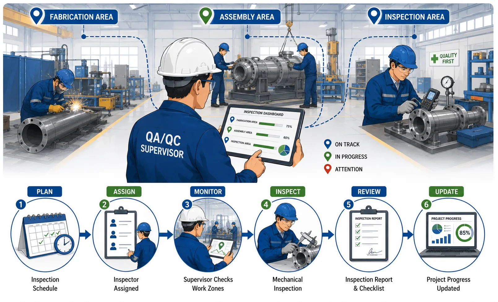
The Purpose of a Project Supervision Framework
A project supervision framework is a structured system that defines how project activities are monitored and controlled. Within mechanical QA/QC, it provides a consistent approach for supervising inspection activities across multiple work areas.
The framework should answer several important questions:
What inspection activities are required?
Where will the inspections take place?
When must each inspection be completed?
Who is responsible for conducting the inspection?
What standards, drawings or specifications apply?
How will progress be recorded?
How will delays or missed inspections be identified?
Who will review inspection performance?
How will critical issues be escalated?
What evidence will demonstrate completion?
A well-designed framework transforms inspection supervision from a reactive activity into a planned management process.
Why Structured Supervision Is Important
Mechanical projects often operate under demanding schedules. Production and construction activities may progress simultaneously in several locations. If inspection planning is weak, an inspector may arrive after a critical activity has already been completed or may fail to recognise that an important hold point is approaching.
Poor supervision can result in:
Missed inspection points.
Delayed quality verification.
Unplanned production stoppages.
Incomplete inspection records.
Uneven distribution of inspectors.
Unresolved non-conformities.
Repeated inspection activities.
Delayed project milestones.
Increased rework.
Reduced confidence in project quality records.
A structured framework helps project leaders maintain visibility and control.
Key Definitions and Concepts
| Term | Definition | Application in Project Supervision |
|---|---|---|
| Project supervision framework | A structured system for planning, monitoring, reviewing and controlling project activities | Provides a consistent method for supervising inspections |
| Inspection progress | The measurable status of planned inspection activities | Shows whether work is on schedule |
| Workshop zone | A defined area within a manufacturing or fabrication facility | Helps organise inspection responsibilities by location |
| Construction site area | A designated physical work location where installation or construction activities occur | Supports area-based inspection planning |
| Inspection schedule | A planned timetable showing when inspections should occur | Aligns inspectors with production or construction activities |
| Inspection and Test Plan (ITP) | A document defining inspection and testing stages, responsibilities and acceptance requirements | Forms a key basis for inspection supervision |
| Hold point | A stage where work must not proceed until required inspection or approval is completed | Requires close supervisory control |
| Witness point | A stage where an authorised party may observe an activity or inspection | Requires advance notification and coordination |
| Inspection status | The recorded condition of an inspection, such as planned, in progress, completed or outstanding | Supports progress monitoring |
| Escalation | The process of referring an issue to a higher level of authority | Ensures significant delays or risks receive attention |
Understanding the Scope of Mechanical Inspection Supervision
Supervising Inspections Across Multiple Locations
Mechanical inspection work may be distributed across a large project. A fabrication workshop may contain separate areas for material storage, cutting, machining, welding, assembly and final inspection. A construction project may contain several work fronts operating simultaneously.
The supervision framework must therefore provide visibility across all relevant locations.
The framework should identify:
All active workshop zones or construction areas.
Major mechanical activities in each location.
Planned inspection requirements.
Assigned inspectors.
Current progress status.
Critical upcoming inspection points.
Outstanding non-conformities.
Resource constraints.
Access or safety restrictions.
This information enables the QA/QC supervisor to understand the overall inspection position rather than relying on isolated reports.
Defining Inspection Boundaries
Clear physical and functional boundaries should be established for each inspection area. This reduces confusion regarding responsibility.
For example, a workshop may be divided into:
Incoming material inspection area.
Cutting and preparation zone.
Machining zone.
Welding zone.
Heat treatment area.
Assembly area.
Final inspection area.
A construction site may be divided according to:
Equipment installation areas.
Pipe rack zones.
Mechanical assembly areas.
Utility systems.
Pump and compressor locations.
Structural support areas.
Each zone should have clearly identified inspection activities and responsible personnel.
Establishing the Project Supervision Structure
Defining the Supervision Hierarchy
A supervision framework should establish a clear reporting and authority structure. Inspectors need to understand who provides daily direction and who has responsibility for resolving technical or operational issues.
A typical structure may include:
Project Manager.
QA/QC Manager.
QA/QC Supervisor.
Discipline Lead or Senior Inspector.
Mechanical Inspectors.
Quality Technicians.
The exact structure will depend on the size and complexity of the project.
Responsibilities of the QA/QC Supervisor
The QA/QC supervisor plays a central role in monitoring inspection progress. The supervisor should maintain an overview of both completed and upcoming activities.
Typical responsibilities include:
Reviewing daily and weekly inspection plans.
Assigning inspectors to specific areas.
Monitoring inspection progress.
Coordinating with production or construction supervisors.
Reviewing inspection reports.
Identifying delays and resource shortages.
Monitoring critical hold points.
Escalating significant quality concerns.
Tracking outstanding non-conformities.
Reporting inspection status to project management.
The supervisor should focus on both current activities and upcoming requirements.
Responsibilities of Mechanical Inspectors
Mechanical inspectors are responsible for carrying out assigned inspection activities in accordance with approved requirements.
Their responsibilities may include:
Reviewing applicable drawings and specifications.
Conducting inspections at assigned locations.
Recording objective evidence.
Identifying non-conforming work.
Reporting inspection results promptly.
Updating inspection status.
Informing the supervisor of emerging issues.
Maintaining professional communication with production personnel.
A reliable supervision system depends on accurate and timely information from inspectors.
Planning Inspection Activities
Developing a Master Inspection Plan
The first practical stage is to establish a master plan showing the overall inspection requirements for the project.
The plan may include:
Project work packages.
Inspection activities.
Planned start dates.
Planned completion dates.
Responsible inspectors.
Applicable inspection documents.
Required resources.
Current status.
Critical milestones.
The master plan should be linked to the broader production or construction schedule.
Breaking the Plan into Zones
Large projects should not be managed as a single inspection list. Dividing activities by physical zone or work package improves control.
For each zone, the supervision framework should identify:
Scope of mechanical work.
Inspection requirements.
Planned work sequence.
Assigned personnel.
Required test equipment.
Key quality risks.
Hold and witness points.
Expected completion dates.
Zone-based planning allows supervisors to identify areas where inspection progress is falling behind.
Daily and Weekly Inspection Planning
The master plan provides the overall structure, but daily and weekly planning is required for active project control.
A daily plan may identify:
Inspections scheduled for the current shift.
Inspectors assigned to each area.
Priority activities.
Critical hold points.
Required documents.
Expected production activities.
A weekly plan may include:
Major inspection milestones.
Expected workload by zone.
Resource requirements.
Upcoming tests.
Potential schedule conflicts.
Outstanding quality issues.
Integrating Inspection Plans with Production and Construction Schedules
Importance of Schedule Alignment
Inspection cannot be effectively supervised in isolation from production or construction activities. Supervisors must understand what work is planned and when critical stages will occur.
For example, if welding is planned in several zones at the same time, the QA/QC supervisor must ensure that inspection resources are sufficient to cover the required activities.
Coordination should include:
Reviewing the production schedule.
Identifying critical mechanical activities.
Forecasting inspection demand.
Confirming inspector availability.
Planning for specialist inspection activities.
Communicating potential conflicts early.
Managing Schedule Changes
Project schedules frequently change due to material delays, equipment breakdowns, weather conditions or client requirements.
The supervision framework should establish how schedule changes are communicated.
A structured response may involve:
Receiving notification of the schedule change.
Assessing the impact on inspection activities.
Reviewing inspector availability.
Revising inspection assignments.
Communicating the updated plan.
Recording significant changes.
Monitoring implementation.
This prevents inspectors from working to outdated schedules.
Establishing Inspection Status Categories
Creating a Standard Progress System
Inspection progress should be measured using consistent categories. If each inspector describes progress differently, supervisors cannot obtain a reliable overall picture.
Typical status categories may include:
Not started.
Planned.
Ready for inspection.
Inspection in progress.
Accepted.
Rejected or non-conforming.
Re-inspection required.
On hold.
Completed and documented.
The project should define these categories clearly.
Using Status for Management Decisions
Inspection status should provide practical management information.
For example:
A large number of activities marked “ready for inspection” may indicate a resource shortage.
Repeated “on hold” status may indicate unresolved technical issues.
Numerous “re-inspection required” activities may suggest recurring production quality problems.
Delayed completion may affect project milestones.
Status information should therefore be analysed rather than simply collected.
Monitoring Progress Through Inspection Registers and Dashboards
The Inspection Register
An inspection register provides a central record of planned and completed activities.
Typical information may include:
Inspection reference number.
Work package.
Zone or location.
Inspection type.
Planned date.
Actual date.
Assigned inspector.
Status.
Result.
Outstanding action.
The register should be regularly updated.
Project Dashboards
For larger projects, a visual dashboard can help management understand inspection performance.
A dashboard may display:
Total planned inspections.
Completed inspections.
Outstanding inspections.
Overdue activities.
Open non-conformities.
Inspections by zone.
Critical upcoming activities.
Inspection workload by inspector.
The purpose is to support decision-making, not merely produce attractive reports.
Monitoring Critical Hold and Witness Points
Hold Points
A hold point represents a stage where work cannot normally proceed until the required inspection or approval has been completed.
Examples may include:
Verification before closure of inaccessible components.
Inspection before pressure testing.
Final dimensional acceptance.
Verification of critical assembly stages.
The supervision framework should provide special monitoring for hold points.
Required controls may include:
Advance notification.
Confirmation of inspector availability.
Review of required documentation.
Clear recording of inspection results.
Formal release before continuation.
Witness Points
A witness point provides an opportunity for an authorised party to observe an activity. The work may proceed according to agreed requirements if the authorised party does not attend after proper notification, depending on the applicable procedure.
The supervisor should ensure:
Required notifications are issued.
Dates and times are communicated.
Evidence of notification is retained.
Attendance or non-attendance is recorded.
Managing Inspection Resources
Assessing Inspector Workload
Supervision includes ensuring that inspection resources match the volume and complexity of planned work.
The supervisor should consider:
Number of active zones.
Complexity of inspections.
Required qualifications.
Shift patterns.
Travel time between locations.
Documentation workload.
Simultaneous critical activities.
An inspector should not be assigned an unrealistic number of critical activities merely to demonstrate high productivity.
Competence-Based Allocation
Inspection tasks should be allocated according to competence and authorisation.
Factors may include:
Technical knowledge.
Inspection experience.
Relevant qualifications.
Certification requirements.
Familiarity with the work scope.
Ability to use required inspection equipment.
The supervision framework should avoid assigning personnel solely based on availability.
Managing Absences and Resource Gaps
Projects should prepare for unexpected personnel shortages.
Possible contingency actions include:
Reprioritising inspection activities.
Reassigning competent personnel.
Adjusting schedules.
Requesting additional qualified inspectors.
Escalating critical resource shortages.
Contingency planning helps prevent missed inspection points.
Conducting Regular Supervisory Reviews
Daily Progress Reviews
Daily reviews enable supervisors to compare planned work with actual progress.
Key questions include:
What inspections were planned?
What inspections were completed?
What activities remain outstanding?
Were any hold points missed?
Are there urgent technical issues?
What work is planned next?
Daily reviews should be concise and evidence-based.
Weekly Performance Reviews
Weekly reviews provide an opportunity to analyse broader trends.
The review may consider:
Inspection completion rates.
Delayed activities.
Re-inspection rates.
Non-conformance trends.
Resource utilisation.
Upcoming milestones.
Repeated communication problems.
The findings should lead to practical actions rather than simply recording statistics.
Establishing a Clear Reporting System
Daily Inspection Reports
Daily reports may summarise activities completed during a shift.
Information may include:
Areas inspected.
Activities completed.
Inspection results.
Non-conformities raised.
Outstanding actions.
Constraints encountered.
The report should provide factual information.
Weekly Supervision Reports
Weekly reports should provide a higher-level overview for management.
They may include:
Overall inspection progress.
Performance against plan.
Major quality issues.
Critical delays.
Resource requirements.
Upcoming priorities.
Recommended actions.
Reporting by Exception
Not every issue requires immediate escalation. However, significant deviations from the plan should be highlighted promptly.
Examples include:
Critical inspection missed.
Major non-conformance.
Serious shortage of competent personnel.
Significant delay affecting a project milestone.
Work progressing without required approval.
Reporting by exception allows management attention to focus on significant risks.
Managing Delays and Inspection Backlogs
Identifying the Cause of Delays
An inspection delay should not automatically be blamed on the inspection team. Supervisors should investigate the actual cause.
Possible causes include:
Late notification from production.
Insufficient inspectors.
Missing documentation.
Incomplete work.
Restricted access.
Equipment availability problems.
Unresolved technical queries.
Changes to the production schedule.
Understanding the cause is essential before corrective action is taken.
Developing Recovery Actions
Where an inspection backlog develops, the supervisor should establish a recovery plan.
Possible actions include:
Prioritising critical activities.
Reallocating inspection resources.
Coordinating revised production sequences.
Extending inspection coverage where authorised.
Requesting additional competent personnel.
Resolving documentation delays.
Recovery actions should be monitored for effectiveness.
Practical Example: Supervising Inspections Across Workshop Zones
Consider a mechanical fabrication workshop divided into four active zones:
Zone A: Material preparation.
Zone B: Machining.
Zone C: Welding and fabrication.
Zone D: Final assembly.
The QA/QC supervisor receives the weekly production schedule and identifies that Zones B and C will have the highest inspection workload.
The supervisor may:
Assign one inspector primarily to machining.
Assign two competent inspectors to welding activities.
Schedule final assembly inspections in advance.
Review critical hold points each morning.
Maintain a central inspection register.
Hold a short daily coordination meeting.
Escalate any resource conflict immediately.
During the week, a production delay in Zone C causes several welding activities to move to the following day. The supervisor updates the inspection plan and reallocates resources to prevent missed inspection points.
This example demonstrates that supervision requires continuous adjustment rather than rigid adherence to an original plan.
Practical Example: Supervising Inspections on a Construction Site
Consider a construction project with multiple mechanical installation areas. Several teams are installing equipment simultaneously.
The supervision framework may divide the site into:
Equipment Area 1.
Equipment Area 2.
Pipework Zone A.
Pipework Zone B.
The QA/QC supervisor establishes:
Area-based inspector assignments.
A daily inspection forecast.
A central register for inspection status.
A weekly progress review.
An escalation process for critical delays.
If Pipework Zone A begins work earlier than planned, the supervisor reviews inspector availability and reallocates competent resources before critical inspections are required.
The framework therefore supports proactive rather than reactive management.
Using Risk-Based Supervision
Prioritising High-Risk Activities
Not all inspection activities have the same consequences. A structured framework should apply greater supervisory attention to activities with higher quality or safety risks.
High-risk factors may include:
Critical mechanical functions.
Difficult-to-access components.
Irreversible manufacturing stages.
Complex assemblies.
Special processes.
Tight project deadlines.
Previous quality problems.
Risk-based supervision helps ensure that management resources are used effectively.
Risk-Based Inspection Priorities
A supervisor may prioritise:
Safety-critical inspections.
Mandatory hold points.
Activities affecting major project milestones.
Areas with repeated non-conformities.
Work that will become inaccessible.
Routine lower-risk inspections.
This approach supports effective decision-making when resources are limited.
Using Digital Tools for Project Supervision
Digital systems can improve the visibility and traceability of inspection progress.
Possible tools include:
Electronic inspection registers.
Document control systems.
Project dashboards.
Mobile inspection applications.
Digital action trackers.
Shared project schedules.
Digital tools should support the supervision process rather than create unnecessary administrative work.
Important principles include:
Access should be controlled.
Information should be current.
Responsibilities should be clear.
Important records should be traceable.
Data should be protected.
Key Benefits of a Structured Project Supervision Framework
Quality Benefits
A structured framework can:
Reduce missed inspection requirements.
Improve consistency between inspection zones.
Strengthen control of hold points.
Improve non-conformance management.
Support complete inspection records.
Project Benefits
It can also:
Improve progress visibility.
Support timely resource allocation.
Reduce inspection-related delays.
Improve coordination with production teams.
Support achievement of project milestones.
Management Benefits
For project leaders, the framework provides:
Reliable progress information.
Early warning of delays.
Evidence for decision-making.
Better workload management.
Clear escalation routes.
Team Benefits
Inspection teams benefit from:
Clear task assignments.
Better understanding of priorities.
Reduced confusion.
More effective communication.
Improved professional accountability.
Developing the Project Supervision Framework Step by Step
Step 1: Define the Inspection Scope
Identify all mechanical activities requiring inspection.
Step 2: Divide the Project into Manageable Zones
Establish physical or functional inspection areas.
Step 3: Review Applicable Requirements
Identify relevant drawings, specifications, ITPs and procedures.
Step 4: Develop the Master Inspection Plan
Establish planned activities, milestones and responsibilities.
Step 5: Allocate Competent Personnel
Assign inspectors according to technical competence and project requirements.
Step 6: Establish Progress Status Categories
Use standard categories to measure inspection progress.
Step 7: Create Daily and Weekly Plans
Translate the overall project plan into practical inspection activities.
Step 8: Monitor Critical Points
Give particular attention to hold points, witness points and high-risk activities.
Step 9: Record and Review Progress
Maintain inspection registers and conduct regular reviews.
Step 10: Manage Delays and Issues
Identify causes, implement corrective actions and escalate significant risks.
Step 11: Report Performance
Provide accurate information to relevant project stakeholders.
Step 12: Continuously Improve the Framework
Review lessons learned and improve supervision methods as project conditions change.
Professional Judgement in Project Supervision
Effective supervision requires more than following a checklist. Supervisors must use professional judgement to determine where attention is most urgently required.
A supervisor may need to decide:
Which inspection activities should receive priority.
Whether additional resources are required.
When a delay creates a significant project risk.
Whether an issue requires escalation.
How to respond to unexpected schedule changes.
Whether inspection evidence is sufficient.
Professional judgement should be supported by:
Approved project requirements.
Objective inspection evidence.
Risk assessment.
Technical knowledge.
Clear organisational procedures.
Consultation with appropriate specialists.
Personal assumptions should not replace evidence-based decisions.
Common Challenges and How to Address Them
Challenge: Incomplete Production Information
If inspectors do not receive accurate production forecasts, inspections may be missed.
Recommended actions:
Establish regular schedule coordination.
Require advance notification for critical activities.
Maintain direct communication with production supervisors.
Review daily work plans.
Challenge: Too Many Simultaneous Inspections
Several zones may require inspection at the same time.
Recommended actions:
Apply risk-based prioritisation.
Reallocate competent personnel.
Forecast workload earlier.
Escalate resource shortages promptly.
Challenge: Delayed Inspection Documentation
Inspection reports may not be completed promptly.
Recommended actions:
Define reporting time requirements.
Use standard templates.
Monitor outstanding records.
Review recurring causes of delay.
Challenge: Repeated Quality Problems
The same defect may appear in different zones.
Recommended actions:
Analyse trends.
Communicate findings across all affected areas.
Coordinate corrective actions with production.
Verify effectiveness.
Conclusion
Establishing a structured project supervision framework is essential for monitoring the progress of mechanical inspections across workshop zones and construction sites. Effective supervision provides visibility over inspection activities, resources, priorities, risks and project milestones. It enables QA/QC supervisors to ensure that inspections are planned, performed and documented at the appropriate stages of mechanical work.
A successful framework integrates the inspection schedule with production and construction activities, divides the project into manageable zones, allocates competent personnel and establishes consistent methods for recording inspection status. It also provides structured processes for monitoring hold points, managing delays, tracking non-conformities and escalating significant risks.
The most effective supervision approach is proactive. Rather than waiting for inspections to become overdue or problems to affect project delivery, supervisors should forecast upcoming activities, monitor progress continuously and respond early to changing conditions.
For Learners and professionals working in mechanical QA/QC, the ability to supervise inspection progress systematically is a key professional competence. By applying structured planning, clear communication, risk-based prioritisation and evidence-based decision-making, project teams can maintain stronger control over mechanical quality activities and support the safe, efficient and successful completion of complex engineering projects.
3.Make Authoritative, Evidence-Backed Decisions Regarding Material Rejections or Stop-Work Orders When Critical Quality Boundaries Are Crossed
Making authoritative decisions regarding material rejection or the suspension of work is one of the most important responsibilities within mechanical QA/QC and project supervision. Mechanical engineering projects often involve expensive materials, complex manufacturing processes, strict client requirements and demanding project schedules. When a critical quality boundary is crossed, delaying or avoiding a decision can allow defective materials or unacceptable work to progress further through the production or construction process.
A competent QA/QC professional must therefore be able to recognise when a quality issue has reached a level that requires formal intervention. This may involve rejecting incoming material, placing material on hold, preventing its use, suspending a particular activity or, where authorised and justified, issuing or recommending a stop-work order. Such decisions must never be based solely on personal opinion, production pressure or assumptions. They should be supported by objective evidence, approved technical requirements, inspection findings, applicable procedures and clearly defined authority.
Authoritative decision-making does not mean acting without consultation or ignoring established procedures. It means exercising professional responsibility within the defined authority of the role and making timely, defensible decisions when evidence demonstrates that quality requirements have not been met.
The central principle is simple: when work or material crosses a defined critical quality boundary, the appropriate action must be taken before the issue creates a greater safety, technical, financial or compliance risk.
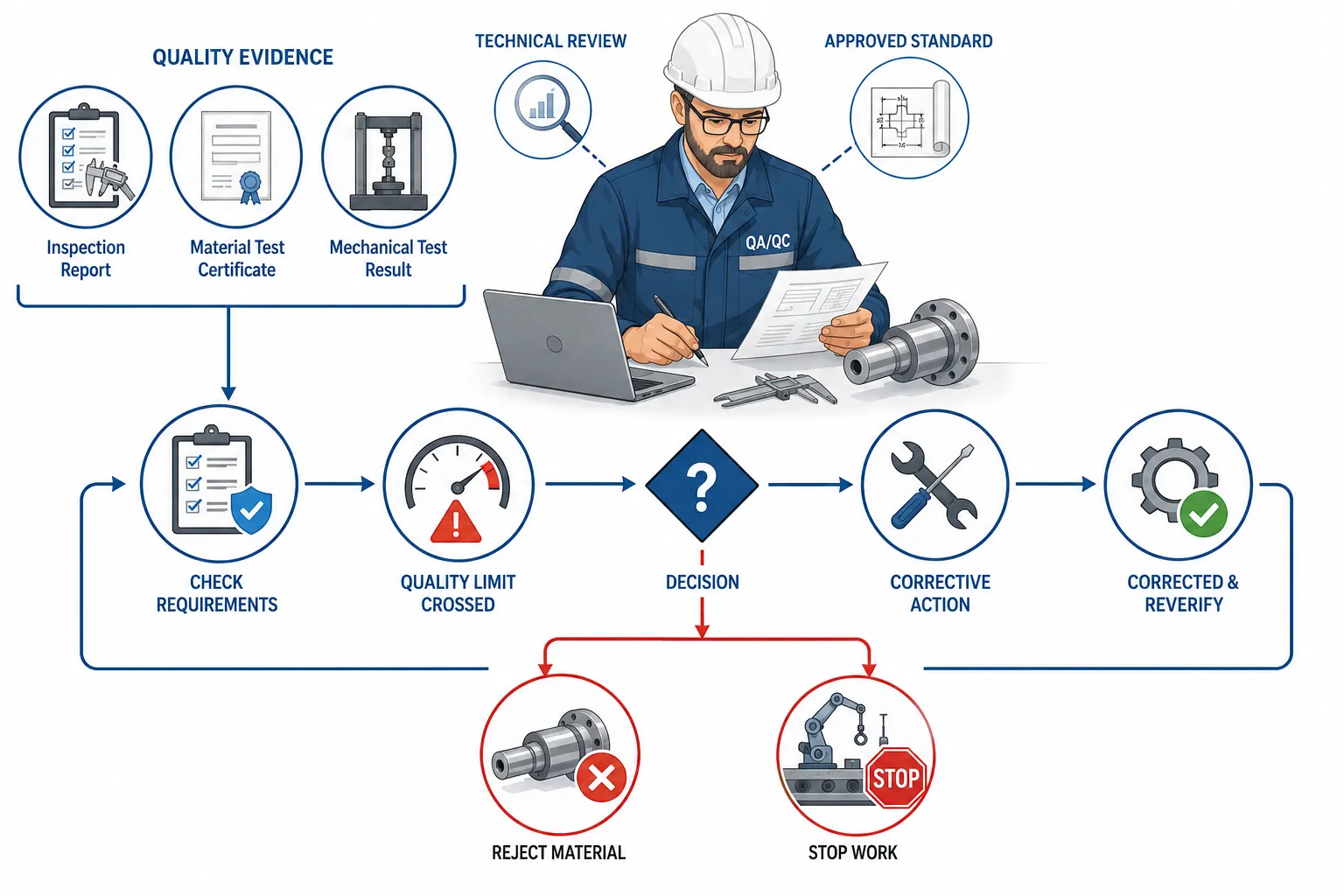
Understanding Critical Quality Boundaries
A critical quality boundary is a defined limit, requirement or acceptance criterion that must not be exceeded without formal engineering evaluation and approval. These boundaries may be established through project specifications, approved drawings, material requirements, inspection and test plans, codes, standards, procedures or legal requirements.
Examples of critical quality boundaries may include:
Material properties outside the specified range.
Missing or invalid material certification.
Incorrect material grade or identification.
Damage that affects material integrity.
Dimensions outside approved tolerances.
Unacceptable welding defects.
Failure of a required mechanical test.
Use of unapproved materials.
Expired or invalid calibration status of critical measuring equipment.
Work progressing beyond a mandatory hold point without inspection.
Unauthorised deviation from approved engineering requirements.
A condition creating a significant safety or structural risk.
A quality boundary provides an objective reference point. The QA/QC professional must compare actual evidence against the approved requirement rather than deciding whether a condition merely “looks acceptable”.
The Difference Between a Minor Issue and a Critical Boundary Breach
Not every quality issue requires material rejection or work suspension. Effective professional judgement requires the ability to distinguish between minor deviations and conditions that create significant risk.
A minor issue may be capable of correction without affecting safety, function or compliance. A critical boundary breach, however, may compromise the integrity of the product, invalidate compliance or allow a serious defect to become concealed or irreversible.
Factors that may indicate a critical breach include:
The defect affects safety-critical performance.
The requirement is mandatory.
The defect cannot be corrected easily after further work.
The material identity cannot be verified.
Test results demonstrate failure against acceptance criteria.
Continued work could conceal evidence.
The issue may affect multiple components.
The condition creates a significant risk of rework.
An approved hold point has been bypassed.
Continued activity could increase the severity of the problem.
The response must be proportionate to the evidence and the potential consequences.
Key Definitions and Concepts
| Term | Definition | Importance in QA/QC Decision-Making |
|---|---|---|
| Material rejection | Formal determination that material does not meet approved requirements and must not be accepted for intended use | Prevents unsuitable material entering production or installation |
| Stop-work order | Formal instruction to suspend an activity because continuing work may create unacceptable quality or safety risks | Prevents further progression of critical non-conforming work |
| Non-conformance | Failure to meet a specified requirement | Provides a formal basis for investigation and corrective action |
| Quality boundary | Defined acceptance limit that separates acceptable and unacceptable conditions | Supports objective and consistent decisions |
| Objective evidence | Verifiable information obtained through inspection, testing, measurement or documented records | Ensures decisions are evidence-based |
| Material traceability | Ability to identify and track material through documentation and identification systems | Supports verification of material conformity |
| Quarantine | Controlled segregation of suspect or non-conforming material | Prevents unintended use |
| Disposition | Formal decision regarding the treatment of non-conforming material or work | Defines actions such as rework, repair, return or rejection |
| Engineering concession | Formal approval to accept or use a deviation under specified conditions | Must not be assumed without authorised approval |
| Root cause analysis | Systematic investigation to identify the underlying cause of a problem | Helps prevent recurrence |
| Corrective action | Action taken to eliminate the cause of a non-conformance | Supports long-term improvement |
| Criticality | The potential seriousness of the consequences associated with a failure or deviation | Helps determine the urgency of intervention |
The Importance of Authoritative Decision-Making
Protecting Safety and Mechanical Integrity
The primary purpose of decisive quality intervention is to protect people, equipment and mechanical systems from the consequences of unacceptable work or materials.
A defective component may initially appear to be a small quality issue. However, if the component performs a critical mechanical function, the consequences of failure may be significant.
For example:
Incorrect material may have inadequate strength.
Unverified material may not withstand operating conditions.
A serious weld defect may reduce structural integrity.
Incorrect dimensions may prevent safe assembly.
A failed pressure-related component may create operational hazards.
An authoritative decision prevents the project from progressing on the basis of uncertainty.
Preventing Defects from Moving Through the Process
The cost and difficulty of correcting a defect usually increase as work progresses.
For example, it is generally easier to isolate incorrect material before fabrication than to identify and remove it after machining, welding, coating, installation and commissioning.
Timely intervention can prevent:
Additional manufacturing costs.
Rework across multiple stages.
Installation delays.
Loss of traceability.
Damage to associated components.
Expensive dismantling.
Client rejection at final inspection.
A stop-work decision may therefore create a short-term delay while preventing a much greater project disruption.
Maintaining Compliance and Professional Integrity
QA/QC professionals may experience pressure to accept questionable materials or allow work to continue in order to protect production schedules.
Professional authority requires decisions to remain based on approved requirements and evidence.
The QA/QC professional should not allow the following factors to replace technical evidence:
Production urgency.
Financial pressure.
Personal relationships.
Informal assurances.
Assumptions about previous practice.
Pressure from senior personnel without appropriate authority.
A belief that the issue will probably not cause a problem.
Compliance must be established through evidence and authorised processes.
Establishing Authority and Responsibility
Understanding Delegated Authority
Not every QA/QC professional has identical authority to reject material or stop work. Authority should be clearly established within the project organisation.
The quality management system should identify:
Who may reject incoming materials.
Who may place material on hold.
Who may issue a stop-work instruction.
Who must approve material disposition.
When engineering approval is required.
Who may authorise work to restart.
How disputes are escalated.
Clear authority prevents confusion during critical situations.
Acting Within the Approved Authority Structure
A QA/QC inspector should understand the limits of their authority.
Depending on the organisation, an inspector may have authority to:
Identify a non-conformance.
Stop a specific inspection process.
Place material in quarantine.
Prevent material release.
Notify the supervisor.
Recommend suspension of work.
A QA/QC manager or project manager may have broader authority to formally suspend a larger activity.
The exact authority must be defined by the organisation and project procedures.
The Importance of Escalation
Where the issue exceeds the authority or competence of the person identifying it, escalation is essential.
A structured escalation process may involve:
Identifying the critical issue.
Collecting immediate objective evidence.
Preventing further uncontrolled progression where authorised.
Informing the responsible supervisor.
Raising a formal non-conformance.
Consulting engineering specialists where required.
Determining the appropriate disposition.
Obtaining formal approval for corrective action.
Verifying completion before release.
Escalation is not a sign of weakness. It is a professional method of ensuring that complex or high-risk decisions receive the correct technical review.
Gathering Objective Evidence Before Making a Decision
Evidence Must Be Relevant and Verifiable
A material rejection or stop-work decision should be supported by evidence that can be reviewed independently.
Useful evidence may include:
Material certificates.
Inspection reports.
Test results.
Dimensional measurement records.
Photographs where appropriate.
Calibration records.
Approved drawings.
Technical specifications.
Inspection and Test Plans.
Traceability records.
Non-destructive testing reports.
Engineering correspondence.
Approved procedures.
The evidence must be directly relevant to the requirement being assessed.
Comparing Actual Conditions Against Requirements
The decision-making process should clearly establish the difference between:
Required condition
and
Actual condition
For example:
Requirement: Material grade must match the approved specification.
Evidence: Material marking and certificate identify a different grade.
Conclusion: The material does not demonstrate conformity with the specified requirement.
This comparison provides a clear and defensible basis for action.
Avoiding Assumption-Based Decisions
A professional should avoid conclusions such as:
“It is probably the correct material.”
“The certificate may be available later.”
“The defect does not look serious.”
“We have used this material before.”
“Production says it is acceptable.”
Such statements do not constitute objective evidence.
The appropriate response is to obtain sufficient information before releasing the material or allowing work to continue.
The Material Rejection Process
Step 1: Identify the Suspect Material
The first step is recognising that the material may not meet requirements.
Possible indicators include:
Incorrect marking.
Missing certificates.
Damage.
Failed testing.
Incorrect dimensions.
Traceability problems.
Unapproved substitution.
The material should not be assumed acceptable until conformity is verified.
Step 2: Verify the Applicable Requirements
The inspector or QA/QC professional should review the approved source of requirements.
This may include:
Purchase specifications.
Approved drawings.
Material data sheets.
Project specifications.
Applicable codes.
Inspection requirements.
The decision must be based on the correct version of the requirement.
Step 3: Collect and Review Evidence
Relevant evidence should be gathered systematically.
The review may include:
Certificate verification.
Physical identification.
Dimensional checks.
Test reports.
Traceability records.
Storage history.
Where evidence is incomplete, the material should not automatically be accepted.
Step 4: Segregate or Quarantine the Material
Suspect material should be clearly controlled to prevent unintended use.
Appropriate actions may include:
Moving the material to a designated quarantine area.
Applying a clear status label.
Restricting access.
Updating the material register.
Informing relevant personnel.
Quarantine is a control measure, not necessarily the final disposition.
Step 5: Raise the Non-Conformance
A formal record should identify:
Material identification.
Location.
Requirement.
Actual condition.
Evidence.
Date of discovery.
Person identifying the issue.
Immediate containment action.
The record should be factual and free from unsupported opinion.
Step 6: Determine the Disposition
Possible outcomes may include:
Return to supplier.
Rework.
Repair where technically authorised.
Further testing.
Engineering review.
Use under an approved concession.
Final rejection.
The decision should follow the approved quality process.
Step 7: Verify Final Action
Material should not be released until the approved disposition has been completed and verified.
Verification may include:
Re-inspection.
Review of new test evidence.
Engineering approval.
Updated traceability records.
Removal of quarantine status.
Understanding Stop-Work Orders
Purpose of a Stop-Work Action
A stop-work action is used when continuing the activity could increase quality or safety risk.
The purpose is to:
Prevent further non-conforming work.
Protect critical evidence.
Allow technical assessment.
Prevent defects becoming concealed.
Maintain compliance with mandatory requirements.
A stop-work action should be targeted and proportionate.
When a Stop-Work Decision May Be Necessary
Potential circumstances include:
Critical work is proceeding without required inspection.
Incorrect material is being installed.
A mandatory hold point has been bypassed.
Serious defects are repeatedly occurring.
Critical test results have failed.
Work is being performed outside approved procedures.
Required quality controls are unavailable.
A significant engineering deviation has not been approved.
The specific authority and process will depend on project procedures.
Immediate Actions Following Work Suspension
When work is stopped, the responsible professional should:
Clearly identify the affected activity.
Communicate the reason.
Prevent unauthorised continuation.
Record the condition.
Preserve relevant evidence.
Notify appropriate management.
Initiate technical review.
The objective is controlled resolution rather than unnecessary disruption.
A Structured Decision-Making Process
Step 1: Recognise the Boundary Breach
Identify the condition that exceeds an approved acceptance limit.
Step 2: Stabilise the Situation
Where authorised, prevent further progression of the affected material or activity.
Step 3: Confirm the Requirement
Review the applicable specification, drawing, procedure or acceptance criterion.
Step 4: Collect Objective Evidence
Gather sufficient information to support the finding.
Step 5: Assess Criticality
Consider:
Safety implications.
Functional consequences.
Scope of affected work.
Potential for further damage.
Reversibility.
Compliance implications.
Step 6: Determine Immediate Containment
Containment may include:
Quarantine.
Work suspension.
Segregation.
Additional inspection.
Temporary hold.
Step 7: Consult Appropriate Technical Authority
Complex cases may require engineering, specialist or management review.
Step 8: Make or Obtain the Formal Decision
The outcome must be consistent with defined authority and approved procedures.
Step 9: Communicate the Decision
Relevant personnel must understand:
What has been stopped or rejected.
Why action was taken.
What requirements apply.
What happens next.
Step 10: Verify Corrective Action and Release
Work should resume only when required corrective actions and approvals have been completed.
Assessing the Criticality of a Quality Issue
Severity
Severity considers the potential consequences if the defect remains.
Questions may include:
Could mechanical integrity be affected?
Could safety be compromised?
Could the product fail during operation?
Could the defect cause significant rework?
Extent
The supervisor should determine whether the issue affects:
One component.
One batch.
One production area.
Multiple work packages.
Previously completed work.
A traceability review may be necessary.
Detectability
Some defects are easy to identify and correct. Others may become hidden after further processing.
Where a defect is likely to become inaccessible, prompt action becomes more important.
Reversibility
The decision should consider whether the work can be corrected later.
Examples of difficult-to-reverse conditions include:
Components already enclosed.
Permanent welded assemblies.
Installed equipment.
Coated surfaces concealing defects.
Practical Example: Incorrect Material Grade
A mechanical inspector receives steel material intended for fabrication. The purchase specification requires a particular material grade. The certificate attached to the material identifies a different grade.
The appropriate professional response may include:
Confirming the approved material requirement.
Checking the material identification.
Reviewing the certificate.
Preventing release for fabrication.
Segregating the material.
Raising a formal non-conformance.
Requesting technical review.
The material should not be accepted simply because it appears physically similar.
The final disposition may depend on an authorised engineering assessment. The QA/QC professional must not independently approve a substitution without the appropriate authority.
Practical Example: Critical Inspection Point Bypassed
A fabrication activity includes a mandatory hold point before a component is closed and becomes inaccessible. The QA/QC supervisor discovers that production has proceeded without the required inspection.
The supervisor should assess:
What work has been completed?
Whether the required evidence can still be obtained.
Whether the component can be reopened.
Whether the missing inspection affects compliance.
Whether additional testing is required.
If continued work would conceal the issue further, suspension of the affected activity may be necessary in accordance with project authority.
Practical Example: Failed Mechanical Test
A mechanical component undergoes a required test and the result falls outside the acceptance criteria.
The QA/QC team should not immediately assume that the entire project is affected. Instead, a structured assessment should determine:
Whether the test result is valid.
Whether the test equipment was correctly calibrated.
Whether the test procedure was followed.
Which materials or components are represented.
Whether additional testing is justified.
If the result is confirmed as valid and demonstrates non-conformity, the affected material or work must be controlled until an authorised disposition is determined.
Communicating Authoritative Decisions
Clear and Professional Communication
A rejection or stop-work decision can create disagreement. Communication should therefore be clear, factual and respectful.
The message should identify:
The affected item or activity.
The applicable requirement.
The evidence observed.
The immediate control action.
The next review stage.
Avoid emotionally charged language or personal criticism.
Example Communication Approach
A professional statement may be structured as follows:
The identified material has been placed on hold because the available certification does not demonstrate conformity with the approved material specification. The material must not be released for use until the non-conformance has been formally reviewed and an authorised disposition has been issued.
This approach focuses on evidence and requirements.
Managing Disputes About Rejection or Stop-Work Decisions
Maintaining Technical Objectivity
Production teams may disagree with a QA/QC decision because of schedule pressure.
The QA/QC professional should return the discussion to:
Approved requirements.
Inspection evidence.
Test results.
Project procedures.
Defined authority.
The purpose is not to “win” an argument but to establish the technically correct course of action.
Escalating Technical Disputes
Where a disagreement concerns interpretation of technical requirements, escalation may be required.
The process may include:
Documenting the issue.
Identifying the exact requirement.
Gathering evidence.
Requesting engineering interpretation.
Recording the formal decision.
Informal verbal agreements should not replace required approval processes.
Key Benefits of Evidence-Backed Decisions
Improved Safety Protection
Evidence-based intervention helps prevent unsafe materials or defective work from progressing.
Stronger Quality Control
Formal decisions provide clear control over non-conforming conditions.
Better Traceability
Documentation demonstrates why a decision was made and what action followed.
Reduced Rework
Early intervention can prevent defects from progressing into later project stages.
Greater Professional Accountability
Decisions supported by objective evidence are more defensible during audits and reviews.
Improved Client Confidence
Consistent quality decisions demonstrate that the organisation maintains control over critical requirements.
Common Mistakes to Avoid
Delaying Action Because of Production Pressure
A known critical issue should not be ignored simply to maintain the schedule.
Rejecting Material Without Confirming Requirements
Material should not be rejected based solely on assumptions or incorrect specifications.
Failing to Segregate Non-Conforming Material
Suspect material can accidentally enter production if it is not properly controlled.
Allowing Informal Verbal Approval
Critical deviations should follow the approved authorisation process.
Stopping More Work Than Necessary
A stop-work action should be proportionate to the identified risk.
Restarting Work Without Verification
Work should not resume merely because a problem is believed to have been resolved.
Developing Professional Judgement
Professional judgement improves through technical knowledge, experience and disciplined use of evidence.
A competent QA/QC professional should:
Understand applicable project requirements.
Recognise critical quality boundaries.
Know the limits of their authority.
Collect reliable evidence.
Assess the consequences of continued work.
Escalate complex decisions appropriately.
Communicate clearly.
Maintain professional independence.
Professional judgement should be neither overly passive nor unnecessarily aggressive. The objective is proportionate, technically justified control.
Best-Practice Checklist for Material Rejection and Stop-Work Decisions
Before finalising a critical decision, consider:
Is the applicable requirement clearly identified?
Is the requirement current and approved?
Is there objective evidence of non-conformity?
Has the extent of the issue been assessed?
Is the condition safety or function critical?
Has immediate containment been applied?
Is the decision within my authority?
Is engineering review required?
Has the issue been formally documented?
Have relevant personnel been informed?
Are corrective actions clearly assigned?
Has verification been planned before release?
Integrating Decisions into the Wider QA/QC System
Material rejection and stop-work decisions should not operate as isolated events. They should form part of the wider quality management process.
The system should connect:
Inspection findings.
Non-conformance reporting.
Material control.
Engineering review.
Corrective action.
Root cause analysis.
Re-inspection.
Final release.
Repeated critical issues should also be analysed for trends.
For example, repeated material identification problems may indicate weaknesses in:
Supplier control.
Receiving inspection.
Storage procedures.
Material traceability.
Personnel training.
The organisation should use these findings to improve the overall system.
Conclusion
Making authoritative, evidence-backed decisions regarding material rejection or stop-work actions is a critical competence in mechanical QA/QC and project supervision. These decisions protect mechanical integrity, maintain compliance, prevent defective work from progressing and support safe project delivery.
Effective decision-making begins with a clear understanding of critical quality boundaries. When a defined requirement is breached, the QA/QC professional must compare objective evidence against approved criteria, assess the seriousness and extent of the issue and apply appropriate containment measures within their authorised responsibilities.
Material rejection may involve identification, verification, quarantine, non-conformance reporting, technical review and formal disposition. Stop-work action may be required where continued work could increase quality or safety risks, conceal evidence or allow critical non-conforming work to progress.
The strongest decisions are not based on personal opinion, production pressure or assumptions. They are supported by verifiable evidence, applicable requirements, documented processes and appropriate technical authority.
Ultimately, professional QA/QC leadership requires the confidence to act when critical boundaries are crossed and the discipline to ensure that every significant decision is proportionate, traceable, technically justified and aligned with approved project procedures. Through this approach, mechanical project teams can prevent unacceptable materials and work from progressing, protect project quality and maintain confidence in the integrity of the final engineering outcome.
4.Design Emergency Response Workflows to Handle Sudden, Major Quality Failures Without Disrupting the Broader Project Timeline
Major quality failures can occur unexpectedly during mechanical manufacturing, fabrication, installation, testing or commissioning activities. A critical material batch may fail testing, a large number of welded joints may show unacceptable defects, essential equipment may be found to be incorrectly manufactured, or a completed mechanical assembly may fail a mandatory performance test. Such events can create immediate risks to safety, compliance, project cost and delivery schedules.
An effective QA/QC organisation must therefore be prepared to respond rapidly and systematically when a major quality failure occurs. Emergency response in this context does not refer only to personal safety emergencies. It also refers to a structured organisational response to a sudden quality event that threatens mechanical integrity, regulatory compliance, contractual requirements or critical project milestones.
The challenge is to control the quality failure without allowing the entire project to become unnecessarily disrupted. A poorly managed response may result in widespread work stoppages, confusion, duplicated inspections, uncontrolled rework and significant delays. Conversely, an effective emergency response workflow isolates the affected area, protects unaffected work, mobilises the appropriate technical resources and establishes a controlled recovery plan.
The central objective is therefore twofold:
Contain and correct the major quality failure.
Protect the continuity of unaffected project activities wherever it is safe and technically appropriate to do so.
A structured emergency response workflow allows project teams to act quickly while maintaining evidence, technical discipline and clear communication.
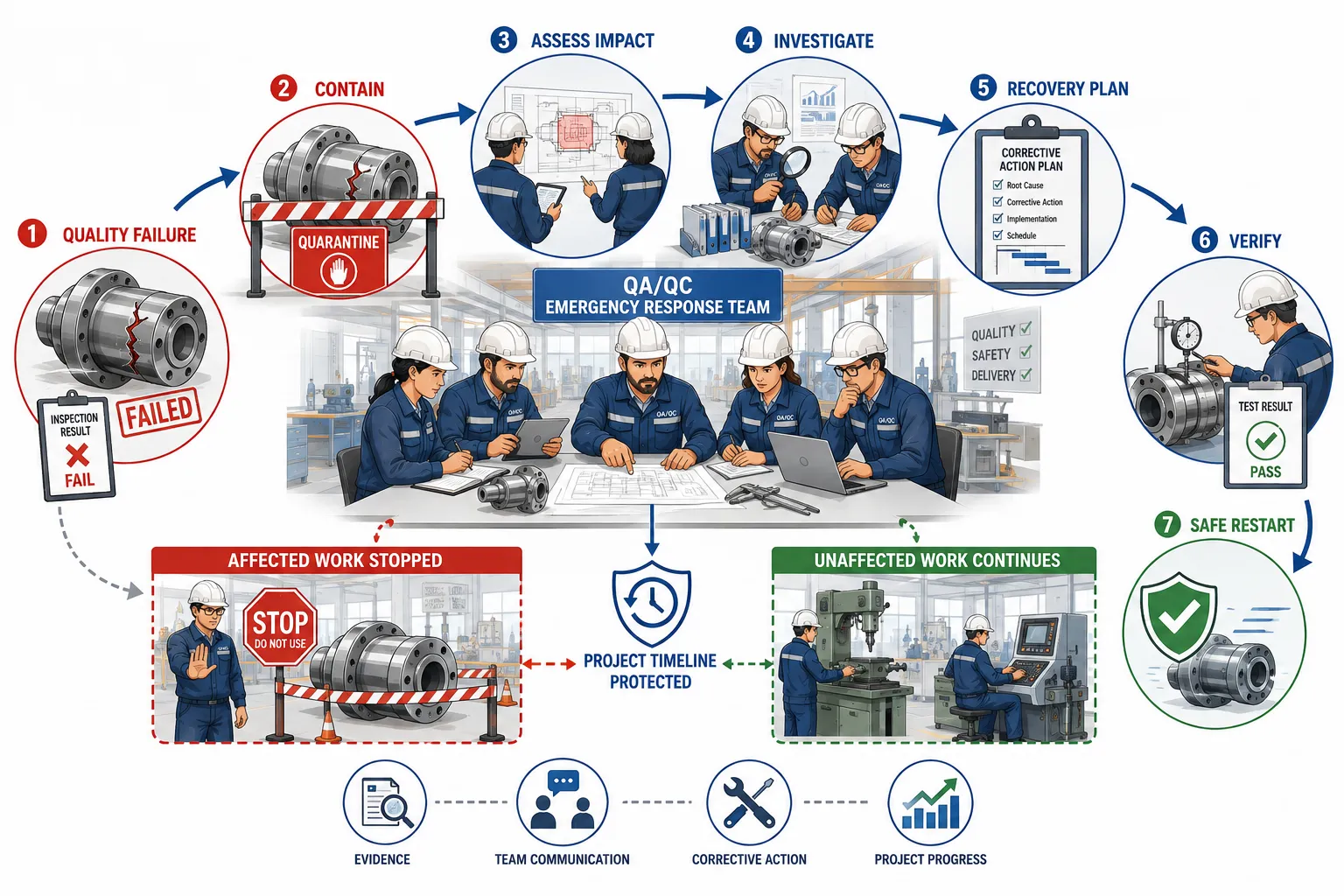
Understanding a Major Quality Failure
A major quality failure is a significant non-conforming condition that has the potential to affect critical project requirements, mechanical performance, safety, regulatory compliance or major project milestones.
The seriousness of a failure depends on its consequences rather than simply its visibility.
Examples may include:
Failure of a critical mechanical component during testing.
Discovery of incorrect material used across multiple assemblies.
A significant batch of welds failing required inspection.
Failure of pressure or performance testing.
Widespread dimensional non-conformity.
Incorrect installation of critical mechanical equipment.
Failure of a specialised manufacturing process.
Loss of traceability for a large quantity of critical material.
Discovery that mandatory inspections were missed across an important work package.
Repeated defects indicating a systemic process failure.
A major quality failure should trigger a structured response based on the defined severity and scope of the event.
Why Emergency Quality Response Workflows Are Necessary
Without a pre-established workflow, project teams may react inconsistently during a major quality event. Production personnel may continue unaffected and affected work without clear boundaries, while QA/QC personnel may attempt to investigate without sufficient authority or coordination.
This can result in:
Further production of defective items.
Loss of important evidence.
Incorrect assumptions about the cause.
Unnecessary suspension of unaffected work.
Conflicting instructions between departments.
Delays in decision-making.
Repeated or ineffective corrective actions.
Increased project cost.
Loss of confidence among clients and stakeholders.
An emergency workflow establishes a common sequence of actions before a crisis occurs.
Key Definitions and Concepts
| Term | Definition | Role in Emergency Quality Response |
|---|---|---|
| Major quality failure | A significant quality event with potentially serious effects on safety, performance, compliance or project delivery | Triggers an enhanced and coordinated response |
| Emergency response workflow | A defined sequence of actions used to control and recover from a critical event | Provides rapid and consistent decision-making |
| Containment | Immediate action taken to prevent a problem from spreading | Limits the scope of the failure |
| Quality incident | A recorded event involving a significant deviation from required quality conditions | Provides a formal starting point for investigation |
| Escalation | The transfer of an issue to a higher or more specialised authority | Ensures appropriate decisions are made |
| Impact assessment | Evaluation of the consequences and extent of a quality failure | Helps determine response priorities |
| Root cause analysis | A structured investigation into the underlying causes of failure | Supports effective long-term correction |
| Recovery plan | A controlled plan for correcting the failure and restoring normal operations | Supports project continuity |
| Critical path | Project activities that directly influence the overall completion date | Requires particular protection during recovery |
| Contingency | A planned alternative action used when normal arrangements are disrupted | Helps maintain project progress |
| Verification | Confirmation through evidence that corrective actions have been completed effectively | Ensures safe and controlled restart |
| Lessons learned | Knowledge obtained from analysing the event and response | Supports continual improvement |
The Core Principles of Emergency Quality Response
Act Quickly but Do Not Act Without Control
A major quality failure often creates pressure for an immediate response. Rapid action is important, but uncontrolled action can make the situation worse.
The first response should focus on stabilising the situation.
Initial priorities include:
Preventing further use of suspect materials.
Preventing continuation of affected work where necessary.
Protecting safety.
Preserving inspection evidence.
Identifying the affected area.
Informing responsible personnel.
The team should avoid making permanent technical decisions before sufficient evidence has been reviewed.
Contain the Failure Without Stopping the Entire Project
One of the most important principles is proportionality.
A major quality failure in one work area does not always justify stopping all project activities. The response should identify precisely what is affected and what can safely continue.
The emergency team should determine:
Which materials are affected.
Which work packages are affected.
Whether the issue is isolated or systemic.
Whether completed work may also be affected.
Which activities can continue safely.
Which activities must be temporarily suspended.
This approach protects the project timeline while maintaining quality control.
Maintain Clear Authority
During a major failure, multiple people may attempt to make decisions simultaneously. This can create confusion.
The workflow should clearly define:
Who leads the emergency response.
Who has authority to stop work.
Who may release work.
Who communicates with project management.
When engineering review is required.
Who approves the recovery plan.
Clear authority supports rapid and consistent decision-making.
Establishing an Emergency Quality Response Team
Purpose of the Response Team
A major quality event may require expertise beyond the normal inspection team. A cross-functional response team can coordinate technical, operational and project decisions.
Depending on the event, the team may include:
QA/QC Manager.
QA/QC Supervisor.
Mechanical Engineer.
Project Manager.
Production Manager.
Site Manager.
Relevant specialist inspector.
Planning or scheduling representative.
Material control representative.
Health and safety representative where relevant.
The composition should reflect the nature of the failure.
Defining Individual Responsibilities
Each member should understand their role.
QA/QC Manager or Supervisor
Responsibilities may include:
Coordinating the quality response.
Ensuring containment.
Reviewing evidence.
Maintaining quality records.
Coordinating investigation activities.
Engineering Representative
Responsibilities may include:
Assessing technical implications.
Reviewing design requirements.
Evaluating possible repair or rework options.
Approving technical solutions within delegated authority.
Project Manager
Responsibilities may include:
Assessing project impact.
Supporting resource mobilisation.
Coordinating senior management decisions.
Managing stakeholder communication.
Production or Construction Manager
Responsibilities may include:
Implementing containment instructions.
Reorganising affected work.
Maintaining progress in unaffected areas.
Supporting corrective action.
Planning Representative
Responsibilities may include:
Assessing schedule impact.
Identifying critical path risks.
Developing recovery scenarios.
Monitoring revised milestones.
Step 1: Detect and Declare the Major Quality Event
Recognising the Trigger
The workflow should define the types of events that require emergency quality response.
Possible triggers include:
Failure of a critical test.
Repeated failure of a major production process.
Discovery of widespread incorrect material.
Major deviation from approved requirements.
Significant loss of material traceability.
Failure affecting a critical project milestone.
Evidence that completed work may be unsafe or non-compliant.
The event should be formally declared according to the organisation’s procedures.
Recording the Initial Information
The initial record should capture factual information.
This may include:
Date and time.
Location.
Work activity.
Materials or equipment involved.
Description of the observed failure.
Immediate risks.
Initial containment action.
Personnel notified.
At this stage, the information should distinguish confirmed facts from assumptions.
Step 2: Apply Immediate Containment
Preventing Further Spread
Containment is the first major control action.
Depending on the event, containment may include:
Stopping the affected process.
Quarantining suspect materials.
Segregating affected components.
Preventing further installation.
Blocking material release.
Increasing inspection controls.
Preserving relevant records.
Containment should be implemented quickly enough to prevent the problem from expanding.
Defining the Containment Boundary
The response team should determine exactly what falls within the affected boundary.
The boundary may be based on:
Material heat or batch numbers.
Production dates.
Equipment identification.
Workshop zones.
Installation areas.
Manufacturing shifts.
Specific work orders.
The boundary should be evidence-based and revised if new information becomes available.
Step 3: Conduct a Rapid Impact Assessment
Assessing Technical Impact
The emergency team should assess:
Does the failure affect mechanical integrity?
Could safety be affected?
Are performance requirements compromised?
Can the defect be corrected?
Is engineering evaluation required?
Assessing Project Impact
The team should also determine:
Which milestones may be affected?
Is the critical path involved?
Can parallel activities continue?
What resources are required?
What additional inspections may be necessary?
Assessing the Scope
The scope assessment should establish whether the failure affects:
A single item.
A production batch.
A complete work package.
Multiple project zones.
Previously completed work.
The initial scope may change as the investigation develops.
Step 4: Protect the Broader Project Timeline
Separate Affected and Unaffected Activities
A major failure should not automatically stop unrelated activities.
The planning and QA/QC teams should classify work into:
Activities that must stop immediately.
Activities that require additional verification.
Activities that may continue normally.
Activities that can be resequenced.
This creates a controlled approach to project continuity.
Use Parallel Workstreams
Where appropriate, unaffected activities can continue while the failure is investigated.
For example:
Investigation proceeds in one fabrication zone.
Assembly continues in an unaffected zone.
Documentation review begins while physical inspections are conducted.
Alternative work packages are brought forward.
Parallel workstreams can reduce overall delay.
Re-Sequencing Project Activities
A planning review may identify work that can be performed earlier than originally planned.
Possible actions include:
Bringing forward unaffected fabrication.
Completing preparatory activities.
Increasing work in unaffected zones.
Conducting inspections in parallel.
Preparing materials for future work stages.
Any resequencing must remain technically and operationally appropriate.
Step 5: Preserve Evidence and Maintain Traceability
Importance of Evidence Preservation
During a major failure, personnel may attempt to repair, move or remove defective items quickly.
This can destroy important evidence.
Before significant alteration, the team should consider:
Photographic evidence.
Material identification.
Test records.
Inspection results.
Process parameters.
Equipment calibration records.
Personnel records where relevant.
Evidence preservation supports accurate investigation.
Maintaining Traceability
The affected items should remain traceable throughout the response.
Records may include:
Identification numbers.
Batch numbers.
Locations.
Inspection status.
Test results.
Disposition status.
Traceability is particularly important when determining the full extent of the problem.
Step 6: Conduct a Structured Technical Investigation
Avoiding Premature Conclusions
A common mistake is to identify the first visible problem and immediately declare it to be the root cause.
For example, a failed weld may be caused by:
Incorrect procedure.
Material contamination.
Equipment malfunction.
Incorrect parameters.
Inadequate preparation.
Human error.
Insufficient supervision.
The investigation should examine evidence before reaching conclusions.
Key Investigation Questions
The response team should ask:
What happened?
When did it happen?
Where did it happen?
How was it detected?
What requirement was not met?
What changed before the failure occurred?
What is the full scope?
What factors contributed?
Root Cause Analysis
Once immediate containment is established, root cause analysis can identify the underlying reasons.
Approaches may include:
Review of process history.
Comparison with approved procedures.
Analysis of inspection records.
Review of material traceability.
Examination of equipment records.
Interviews with relevant personnel.
Analysis of process changes.
The objective is to prevent recurrence, not simply identify an individual to blame.
Step 7: Develop a Controlled Recovery Plan
Purpose of the Recovery Plan
A recovery plan explains how the project will move from the current disrupted condition to controlled normal operation.
The plan should address both:
Quality recovery.
Schedule recovery.
Key Elements of a Recovery Plan
A robust plan may include:
Description of the failure.
Containment status.
Scope of affected work.
Required technical actions.
Rework or repair requirements.
Additional inspection requirements.
Responsible personnel.
Required resources.
Planned completion dates.
Verification requirements.
Restart criteria.
The plan should be approved according to project authority.
Establishing Priorities
The recovery plan should prioritise actions according to:
Safety.
Mechanical integrity.
Critical path impact.
Technical complexity.
Availability of resources.
This prevents resources being wasted on low-priority activities while critical issues remain unresolved.
Step 8: Mobilise Resources Efficiently
Identifying Required Resources
Major failures may require additional support.
Resources may include:
Specialist inspectors.
Mechanical engineers.
Testing personnel.
Additional equipment.
Replacement materials.
Planning support.
Document control personnel.
The project should mobilise only the resources required for effective recovery.
Avoiding Resource Disruption
Removing personnel from unaffected critical activities may create new project delays.
Resource decisions should therefore consider the wider project impact.
Possible approaches include:
Temporary specialist support.
Controlled overtime where authorised.
Reallocation of non-critical resources.
External technical support.
Step 9: Communicate Through a Structured Escalation Process
Internal Communication
Relevant personnel should receive accurate and consistent information.
Communication should clarify:
What happened.
What is affected.
What actions are currently in place.
Which activities may continue.
What decisions are pending.
Who is responsible for updates.
Avoiding Conflicting Messages
A major quality event should have a controlled communication route.
The organisation should avoid situations where:
Production receives one instruction.
QA/QC provides another.
Engineering communicates a different interpretation.
A designated response leader should coordinate formal updates.
Escalating to Senior Management
Senior management should be informed when the event:
Threatens major milestones.
Creates significant financial impact.
Involves major compliance concerns.
Requires additional resources.
May affect client commitments.
Escalation should provide factual information and clear options.
Step 10: Implement Corrective and Recovery Actions
Correcting the Immediate Problem
Corrective actions may include:
Removing defective materials.
Reworking components.
Repeating tests.
Repairing acceptable items under approved procedures.
Replacing affected components.
Revising a defective process.
All actions should be technically authorised where required.
Preventing Recurrence
Long-term corrective actions may involve:
Updating procedures.
Improving inspection controls.
Providing additional competence development.
Improving material identification.
Revising process monitoring.
Strengthening supervision.
A major event should result in organisational learning.
Step 11: Verify Effectiveness Before Restarting Work
Verification Is Essential
A project should not return to normal operations simply because corrective actions have been completed.
The response team should verify:
The immediate failure has been addressed.
The root cause has been appropriately controlled.
Corrective actions have been completed.
Required inspections have passed.
Affected materials have been properly dispositioned.
Restart conditions have been met.
Establishing Restart Criteria
Clear restart criteria may include:
Engineering approval obtained where required.
Corrective action completed.
Required inspections passed.
Test evidence accepted.
Personnel informed.
Procedures available and current.
Restart authority should be clearly documented.
Practical Example: Widespread Welding Quality Failure
A project discovers that a significant number of welded joints have failed required inspection.
The emergency workflow may proceed as follows:
Identify the affected welds and related production period.
Suspend the affected welding activity where required.
Allow unrelated workshop activities to continue.
Preserve welding and inspection records.
Identify the full population of potentially affected welds.
Conduct additional technical evaluation.
Investigate possible process causes.
Develop an approved repair or rework plan.
Re-sequence unaffected project work.
Verify repaired work before release.
The project avoids unnecessary total shutdown while maintaining strict control over the affected work.
Practical Example: Critical Material Batch Failure
A batch of mechanical material fails a required verification test after some material has already been issued to production.
The response team should:
Stop further release of the batch.
Identify where issued material has been used.
Review traceability records.
Quarantine remaining stock.
Assess completed components.
Determine whether additional testing is required.
Obtain technical decisions regarding affected work.
Continue production using verified unaffected materials where possible.
The key objective is to define the exact impact rather than stopping all production without evidence.
Designing a Practical Emergency Response Workflow
Phase 1: Detection
The workflow begins when a significant quality event is identified.
Key actions:
Detect the abnormal condition.
Record initial facts.
Notify the appropriate authority.
Assess immediate risk.
Phase 2: Containment
The immediate objective is preventing further spread.
Key actions:
Stop affected work where required.
Quarantine materials.
Identify affected areas.
Protect evidence.
Phase 3: Assessment
The response team determines seriousness and scope.
Key actions:
Review requirements.
Assess technical consequences.
Identify affected work.
Assess schedule impact.
Phase 4: Investigation
The underlying causes are examined.
Key actions:
Review records.
Analyse processes.
Identify contributing factors.
Confirm root causes.
Phase 5: Recovery
A controlled plan is implemented.
Key actions:
Correct affected work.
Reallocate resources.
Re-sequence unaffected activities.
Complete additional inspections.
Phase 6: Verification and Restart
The project confirms that controls are effective.
Key actions:
Verify corrective actions.
Review inspection evidence.
Confirm restart criteria.
Authorise controlled resumption.
Phase 7: Lessons Learned
The organisation improves future readiness.
Key actions:
Review response effectiveness.
Identify improvements.
Update procedures.
Share relevant lessons.
Key Benefits of a Structured Emergency Response Workflow
Faster Containment
A defined process enables personnel to act quickly without confusion.
Reduced Project Disruption
Targeted containment allows unaffected activities to continue where appropriate.
Better Technical Decisions
Structured evidence collection supports reliable engineering judgement.
Protection of Critical Milestones
Schedule recovery and work resequencing reduce unnecessary impact on the project timeline.
Improved Communication
Clear authority and reporting reduce conflicting instructions.
Stronger Organisational Learning
Root cause analysis and lessons learned help prevent similar events.
Common Challenges in Managing Major Quality Failures
Challenge: Pressure to Continue Work
Production pressure may encourage personnel to continue before the issue is fully assessed.
Recommended response:
Refer to approved requirements.
Define the affected boundary.
Apply proportionate containment.
Escalate where required.
Challenge: Stopping Too Much Work
An overly broad response can create unnecessary delay.
Recommended response:
Use evidence to identify the actual scope.
Separate affected and unaffected activities.
Continue verified work where appropriate.
Challenge: Incomplete Traceability
Poor records may make it difficult to identify affected materials.
Recommended response:
Strengthen document and material control.
Review available evidence.
Apply conservative boundaries where uncertainty remains.
Improve future traceability systems.
Challenge: Premature Root Cause Conclusions
Teams may blame one visible factor without sufficient evidence.
Recommended response:
Use structured investigation.
Review multiple possible causes.
Verify conclusions before implementing permanent actions.
Challenge: Delayed Communication
Late communication can allow further affected work to proceed.
Recommended response:
Establish clear notification triggers.
Define escalation responsibilities.
Use timely and controlled project updates.
Best-Practice Checklist for Emergency Quality Response
When designing or implementing an emergency response workflow, ensure that the system can answer the following questions:
What events trigger emergency quality response?
Who has authority to lead the response?
How is affected work immediately contained?
How are suspect materials controlled?
How is evidence preserved?
How is the scope determined?
Which activities can safely continue?
How are critical project milestones protected?
Who performs technical investigation?
How are corrective actions approved?
What criteria permit work to restart?
How are lessons learned recorded?
Professional Judgement and Leadership During a Quality Emergency
A major quality failure tests the leadership capability of the QA/QC team. Effective leaders must remain objective even when there is significant pressure to restore production quickly.
Professional leadership requires:
Calm decision-making.
Clear communication.
Evidence-based judgement.
Appropriate escalation.
Respect for technical authority.
Protection of quality requirements.
Awareness of project priorities.
The strongest response is neither excessive shutdown nor uncontrolled continuation. It is a proportionate, evidence-based approach that controls the affected issue while protecting safe and compliant progress elsewhere.
Conclusion
Designing emergency response workflows for sudden major quality failures is a critical aspect of project supervision and QA/QC leadership in mechanical engineering. Major failures can threaten mechanical integrity, project milestones, compliance and client confidence. However, a well-designed response system enables the project team to contain the problem rapidly without unnecessarily disrupting unaffected activities.
An effective workflow begins with early detection and immediate containment. It then progresses through impact assessment, evidence preservation, technical investigation and structured recovery planning. Clear authority, cross-functional coordination and effective communication are essential throughout the process.
Protecting the broader project timeline requires a disciplined approach. Teams should separate affected work from unaffected activities, use parallel workstreams where appropriate and re-sequence project tasks without compromising quality requirements. Recovery should focus not only on correcting the immediate failure but also on identifying and controlling its underlying causes.
Before work resumes, corrective actions must be verified and formal restart criteria must be satisfied. The final stage should capture lessons learned so that future projects can respond more effectively.
For QA/QC professionals, the ability to manage a major quality emergency demonstrates advanced leadership, professional judgement and project management competence. By applying a structured emergency response workflow, mechanical project teams can respond confidently to unexpected quality failures, protect critical engineering requirements and maintain the greatest possible continuity across the broader project.