
Lesson no 2 : Identify, assess, and mitigate risks in mechanical systems and manufacturing processes.
Introduction
Mechanical systems and manufacturing processes operate within complex environments where technical failures, human error, equipment limitations, unsafe working practices, material defects and process variations can create significant risks. The ability to identify, assess and mitigate these risks is therefore a fundamental responsibility within mechanical engineering, manufacturing, QA/QC and project supervision. Effective risk management helps organisations protect people, equipment, products, the environment and overall project performance while maintaining compliance with applicable safety, quality and operational requirements.
This lesson introduces Learners to a structured approach for recognising hazards and potential failures within mechanical systems and manufacturing activities. Risk identification involves examining equipment, materials, processes, working conditions and human activities to determine what could go wrong and what consequences may result. Common risks may include machinery failure, mechanical defects, incorrect installation, welding faults, material damage, inadequate maintenance, process deviations and failures in inspection or testing activities.
Once a risk has been identified, it must be assessed systematically. This normally involves considering the likelihood of an unwanted event occurring and the potential severity of its consequences. Risk assessment enables engineering and quality teams to prioritise significant risks and focus resources on areas requiring immediate control or improvement.
Risk mitigation involves selecting and implementing appropriate measures to eliminate hazards where possible or reduce their likelihood and impact. These measures may include improved engineering controls, preventive maintenance, inspection and testing, competent supervision, safe operating procedures, training, quality checks and continuous monitoring.
The lesson also emphasises the importance of documenting risk assessments, communicating findings to relevant teams and regularly reviewing control measures as mechanical systems and manufacturing conditions change. Effective risk management is not a one-time activity; it is a continuous process that supports informed decision-making throughout the lifecycle of a mechanical project or manufacturing operation.
By developing competence in identifying hazards, evaluating risks and applying suitable mitigation strategies, Learners will be better prepared to support safer, more reliable and higher-quality mechanical systems and manufacturing processes. This knowledge is essential for QA/QC professionals, mechanical inspectors, supervisors and engineering personnel responsible for maintaining operational control and supporting continual improvement.
1.Analyse Manufacturing Workflows and Mechanical Designs to Identify Quality Blind Spots, Material Hazards and Process Weak Points
Effective risk management in mechanical engineering and manufacturing begins with a detailed understanding of how a product is designed, manufactured, inspected, tested and released. Manufacturing failures rarely occur without warning. In many cases, weaknesses exist within the design, workflow, material selection, inspection arrangements or communication processes before a visible defect appears. The ability to analyse these areas systematically enables QA/QC professionals and engineering teams to identify potential risks early and introduce suitable controls before they affect safety, quality, cost or project delivery.
A manufacturing workflow should therefore be viewed as an interconnected system rather than a series of isolated activities. A weakness at one stage can influence several later stages. For example, incorrect material identification during receiving inspection may result in unsuitable material being issued to fabrication. If the error is not detected during fit-up, welding, inspection or testing, the final component may fail to meet its required mechanical or operational performance.
Similarly, a mechanical design may appear satisfactory when reviewed only at a general level but may contain hidden weaknesses relating to tolerances, material compatibility, access for inspection, manufacturing feasibility or operating conditions. Identifying these blind spots requires technical knowledge, systematic analysis and effective communication between design, production, QA/QC and inspection personnel.
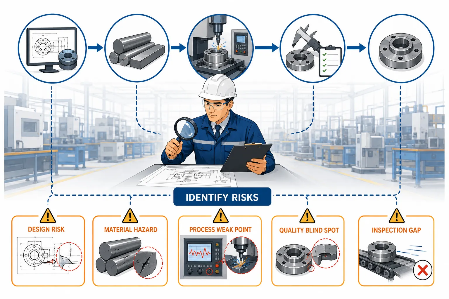
Key Definitions and Concepts
The following concepts are fundamental when analysing manufacturing workflows and mechanical designs.
| Term | Definition | Practical Importance |
|---|---|---|
| Quality blind spot | An area of a process, design or control system where a potential defect or failure may remain unnoticed | Helps teams identify gaps in inspection and verification |
| Material hazard | A risk associated with the properties, condition, handling or compatibility of a material | Supports safe and reliable material selection and use |
| Process weak point | A stage where variation, error or inadequate control can significantly affect the final result | Helps prioritise preventive controls |
| Workflow analysis | The systematic examination of activities, inputs, outputs and responsibilities within a process | Reveals dependencies and potential failures |
| Design review | A structured evaluation of a mechanical design against functional and manufacturing requirements | Identifies weaknesses before production |
| Critical control point | A stage where effective control is necessary to prevent or detect significant non-conformity | Supports focused QA/QC planning |
| Failure mode | A specific way in which a component, material or process may fail | Supports proactive risk assessment |
| Root cause | The underlying reason why a problem or weakness occurs | Prevents repeated failures |
Understanding Manufacturing Workflow Analysis
The Purpose of Workflow Analysis
Manufacturing workflow analysis involves mapping and examining every significant stage through which materials and components pass. The purpose is not simply to understand the sequence of activities. The deeper objective is to determine where errors can enter the process, where they can remain undetected and where they can create serious consequences.
A typical mechanical manufacturing workflow may include:
Design and engineering review
Material specification
Supplier selection and purchasing
Material receiving
Material identification
Storage and preservation
Cutting and preparation
Forming or machining
Fit-up and assembly
Welding or joining
Heat treatment where applicable
Dimensional inspection
Non-destructive or other testing
Surface preparation and coating
Final inspection
Documentation review
Client or project handover
Every stage has inputs, activities and outputs. A weakness in any of these areas can affect subsequent stages.
For example:
An incorrect drawing revision may result in incorrect fabrication.
Incorrect material storage may cause corrosion or contamination.
Poor cutting accuracy may create dimensional problems during assembly.
Inadequate fit-up inspection may allow misalignment to continue.
Incorrect welding parameters may reduce joint quality.
Insufficient inspection coverage may leave defects undiscovered.
Incomplete documentation may prevent traceability.
Analysing Inputs, Activities and Outputs
A practical method of workflow analysis is to examine each stage using three questions:
What enters the process?
What happens during the process?
What result should leave the process?
This approach allows the team to identify weaknesses systematically.
For each activity, the analysis should consider:
Required drawings and specifications
Material condition
Equipment suitability
Personnel competence
Approved procedures
Inspection requirements
Acceptance criteria
Records and documentation
Potential failure modes
Downstream consequences
A process may appear to be functioning correctly while a significant control gap remains hidden. This is why workflow analysis must examine both visible activities and supporting systems.
Identifying Quality Blind Spots
What Is a Quality Blind Spot?
A quality blind spot is an area where a defect, deviation or developing problem is not adequately recognised by existing controls. The organisation may believe that quality is being managed effectively, while an important activity receives insufficient inspection, monitoring or verification.
Quality blind spots can occur because of:
Incomplete inspection plans
Assumptions that earlier checks are sufficient
Poor communication between departments
Unclear responsibilities
Outdated procedures
Inadequate sampling
Missing acceptance criteria
Excessive reliance on visual inspection
Incomplete documentation
Changes to the manufacturing process without updated controls
Common Sources of Quality Blind Spots
Handover Between Departments
Many defects occur at the point where responsibility passes from one department to another. For example, engineering may release a drawing, but production personnel may not receive information about a critical design requirement.
Potential handover risks include:
Incorrect drawing revisions
Missing technical notes
Unclear acceptance criteria
Uncommunicated design changes
Incomplete material information
Undefined inspection responsibility
A strong QA/QC system should clearly identify who is responsible for transferring, receiving and confirming critical information.
Inadequate Inspection Coverage
A process may have inspections but still contain blind spots. The issue is whether inspections cover the most critical risks.
Examples include:
Inspecting only final products rather than intermediate stages
Checking dimensions but not material identity
Verifying appearance without confirming internal quality
Reviewing certificates without checking traceability
Inspecting completed work when defects can no longer be corrected easily
Inspection planning should therefore focus on risk and consequence rather than simply applying the same checks to every activity.
Assumptions About Supplier Quality
A common blind spot occurs when organisations assume that supplied materials are acceptable because they originate from an approved supplier. Supplier approval does not remove the need for receiving inspection and verification.
Potential issues may include:
Incorrect material grade
Damaged material during transport
Missing certificates
Incorrect heat or batch identification
Material substitution
Expired preservation requirements
Analysing Mechanical Designs for Hidden Weaknesses
Design Risk Begins Before Manufacturing
Mechanical design decisions directly influence manufacturing quality. A component may satisfy theoretical performance requirements but still be difficult to manufacture, inspect or maintain.
Design analysis should therefore consider:
Functional requirements
Operating loads
Material suitability
Manufacturing capability
Tolerance requirements
Assembly requirements
Inspection accessibility
Testing requirements
Environmental conditions
Maintenance needs
A design should not be evaluated only by asking whether it works in theory. Engineering teams should also ask whether it can be manufactured consistently and verified effectively.
Tolerance-Related Weak Points
Tolerances define acceptable variation. Excessively tight tolerances may increase manufacturing difficulty and cost, while excessively broad tolerances may create functional problems.
When analysing tolerances, teams should consider:
Manufacturing capability
Measurement capability
Assembly requirements
Accumulated tolerance effects
Thermal expansion
Operating loads
Wear and movement
A component may meet individual dimensional tolerances while the complete assembly fails because small variations accumulate across several components.
Accessibility for Inspection
A design may contain areas that cannot be adequately inspected after assembly. This creates a major quality blind spot.
Examples include:
Internal surfaces inaccessible after joining
Weld areas hidden by later components
Measurement points blocked by assemblies
Components requiring testing before final installation
Design reviews should identify inspection requirements early so that hold points or intermediate inspections can be introduced.
Material Hazards in Mechanical Manufacturing
Understanding Material-Related Risk
Material hazards include risks arising from incorrect selection, deterioration, contamination, incompatibility or improper handling.
Materials are not interchangeable simply because they have a similar appearance. Mechanical properties, chemical composition and environmental resistance can vary significantly.
Material-related risks may include:
Incorrect grade selection
Loss of material traceability
Corrosion
Contamination
Moisture damage
Improper storage
Mixing of similar materials
Heat damage
Incompatible material combinations
Material Identification and Traceability
Traceability connects the physical material to its supporting documentation. Without effective traceability, the organisation may be unable to confirm the origin, specification or test history of a component.
A material control process should normally include:
Unique identification
Certificate verification
Receiving inspection
Controlled storage
Controlled issue
Traceability transfer during cutting
Record retention
When material is cut into smaller pieces, the original identification may be lost unless an appropriate transfer system is used.
Material Compatibility
Two materials may perform satisfactorily when used separately but create problems when combined.
Compatibility analysis may consider:
Corrosion behaviour
Thermal expansion
Chemical exposure
Operating temperature
Mechanical strength
Joining methods
For example, components exposed to different rates of thermal expansion may experience stress during temperature changes.
Identifying Process Weak Points
What Makes a Process Stage Vulnerable?
A process weak point is an activity where variation can enter the manufacturing system or where existing controls are insufficient to detect problems.
Weak points are often associated with:
High technical complexity
Manual operations
Frequent process changes
Limited inspection access
High dependence on individual competence
Critical equipment settings
Difficult environmental conditions
Time pressure
Human Factors
Human performance is an important consideration in manufacturing risk analysis. Even competent personnel can make mistakes when processes are unclear or working conditions are poor.
Common human-factor risks include:
Misreading drawings
Using outdated documents
Incorrect equipment settings
Skipping verification steps
Misidentifying materials
Incomplete records
Fatigue
Poor communication
Controls may include:
Clear procedures
Competence verification
Effective supervision
Independent checks
Controlled documentation
Practical training
Appropriate workload management
Equipment and Tooling Weaknesses
Manufacturing equipment must be capable of producing the required result.
Potential equipment-related risks include:
Calibration failure
Tool wear
Incorrect machine settings
Inadequate maintenance
Measurement uncertainty
Equipment breakdown
Workflow analysis should therefore consider whether equipment controls are adequate at each critical stage.
A Structured Process for Analysing Risks
Step 1: Define the Manufacturing System
The first step is to understand the complete process from input to final delivery.
The team should identify:
Process boundaries
Major activities
Responsible personnel
Inputs and outputs
Critical equipment
Applicable requirements
A clear process map helps prevent important stages from being overlooked.
Step 2: Identify Critical Activities
Not every process step carries the same level of risk. Critical activities should be identified according to their potential effect on safety, quality and project performance.
Examples may include:
Material verification
Critical machining
Welding
Heat treatment
Pressure-related testing
Final assembly
Functional testing
Step 3: Identify Potential Failure Modes
For each critical activity, the team should ask:
What could go wrong?
Why could it happen?
How would it be detected?
What would happen if it remained undetected?
This approach encourages proactive thinking.
Step 4: Review Existing Controls
Existing controls may include:
Procedures
Inspection points
Competence requirements
Equipment calibration
Supervisor checks
Testing
Documentation
The key question is whether the control is genuinely effective.
Step 5: Identify Control Gaps
A control gap exists when a significant risk is not adequately prevented or detected.
Examples include:
No inspection after a critical process
Unclear responsibility
Missing acceptance criteria
Inadequate traceability
Outdated procedures
Step 6: Introduce Appropriate Improvements
Improvements should be proportionate to the identified risk.
Possible actions include:
Adding inspection points
Revising procedures
Improving traceability
Providing additional training
Introducing independent verification
Improving process monitoring
Step 7: Monitor Effectiveness
Risk controls should not simply be implemented and forgotten. Their effectiveness should be monitored using evidence.
Useful evidence may include:
Inspection results
Non-conformity trends
Rework data
Audit findings
Testing outcomes
Customer feedback
Using Risk-Based Thinking in QA/QC
Risk-based thinking encourages teams to focus resources where failure would have the greatest consequence.
A risk-based approach may consider:
Severity of potential consequences
Likelihood of occurrence
Ability to detect the problem
Exposure of personnel or equipment
Cost of failure
Effect on project milestones
Higher-risk activities generally require stronger controls.
Examples include:
Increased inspection frequency
Independent verification
Hold points
Specialist review
Additional testing
Practical Example: Fabricated Mechanical Assembly
Consider a mechanical assembly involving material cutting, machining, welding and final inspection.
The workflow analysis identifies the following:
Material certificates are checked at receiving.
Material markings may be removed during cutting.
Traceability transfer is inconsistent.
Final inspection checks dimensions but cannot confirm original material identity.
This represents a quality blind spot.
A suitable mitigation approach may include:
Controlled transfer of identification before cutting
Clear marking requirements
Traceability records for individual components
Verification during fabrication
The improvement is more effective than relying solely on final inspection.
Practical Example: Design for Inspection
A mechanical component contains an internal joint that cannot be inspected after final assembly.
A design review identifies that:
The joint is safety-critical.
Visual inspection will be impossible after assembly.
Testing is only possible before installation.
The team may introduce:
A mandatory pre-assembly inspection
A documented hold point
Specific acceptance criteria
Required inspection records
This demonstrates how early design analysis can prevent a future quality blind spot.
Benefits of Early Identification of Weak Points
Improved Product Quality
Early identification reduces the likelihood that defects will progress through multiple manufacturing stages.
Key benefits include:
Reduced rework
Improved consistency
Better compliance
Earlier defect detection
Improved Safety
Risk analysis can identify conditions that may threaten personnel or equipment.
This may support:
Safer work planning
Improved hazard controls
Better equipment management
Reduced exposure to dangerous failures
Reduced Cost of Failure
The cost of correcting a defect generally increases as the product moves through the manufacturing process.
Early controls can reduce:
Scrap
Rework
Delays
Material waste
Warranty issues
Better Decision-Making
Structured analysis provides evidence for technical decisions.
It helps leaders:
Prioritise resources
Focus inspections
Improve procedures
Manage project risks
Communication and Team Involvement
Why Cross-Functional Input Matters
Manufacturing risks are often best identified by people from different functions. Designers may understand theoretical requirements, while production personnel understand practical manufacturing difficulties.
A comprehensive review may involve:
Mechanical engineers
QA/QC personnel
Inspectors
Production supervisors
Maintenance personnel
Material specialists
Each group may identify different risks.
Effective Risk Communication
Findings should be communicated clearly and practically.
A useful risk communication process may include:
Describing the risk
Explaining potential consequences
Identifying responsible persons
Defining required controls
Recording completion dates
Reviewing effectiveness
Technical information should be translated into clear instructions for the people performing the work.
Continuous Improvement Through Risk Analysis
Manufacturing workflows and mechanical designs should be reviewed throughout the project lifecycle. New risks can emerge when:
Designs change
Materials are substituted
Equipment is replaced
Production volumes increase
New personnel join the team
Non-conformities occur
Continuous improvement requires organisations to learn from operational evidence.
Useful improvement activities include:
Reviewing recurring defects
Analysing inspection trends
Investigating root causes
Updating procedures
Sharing lessons learned
Professional Responsibilities of QA/QC Personnel
QA/QC professionals play a critical role in identifying blind spots and process weaknesses. Their responsibility is not limited to detecting completed defects. They should support preventive quality management.
Professional responsibilities include:
Reviewing manufacturing processes objectively
Identifying gaps in inspection coverage
Checking material traceability
Raising concerns using evidence
Supporting corrective action
Monitoring control effectiveness
Effective QA/QC practice requires professional judgement. Personnel should avoid assuming that an existing procedure is automatically effective simply because it has been approved.
Key Points for Learners
When analysing manufacturing workflows and mechanical designs, remember that:
Quality risks can begin during design.
A process can contain inspections and still have blind spots.
Material identification and traceability are critical controls.
Handover points between departments require careful management.
Human factors can create significant process variation.
Critical activities require proportionate inspection and control.
Final inspection alone cannot detect every problem.
Early identification of weak points reduces the cost of failure.
Cross-functional teamwork improves risk identification.
Risk controls must be reviewed for continued effectiveness.
Conclusion
Analysing manufacturing workflows and mechanical designs is a proactive approach to identifying quality blind spots, material hazards and process weak points before they develop into serious failures. Effective analysis requires a detailed understanding of the complete manufacturing system, including design decisions, material controls, production activities, inspection arrangements, equipment capability and human factors.
QA/QC professionals and mechanical engineering teams must examine not only whether a process has controls but also whether those controls are positioned correctly and capable of preventing or detecting significant failures. Particular attention should be given to critical handover points, material traceability, inspection accessibility, process variation and activities where defects may become hidden.
By applying structured workflow analysis, reviewing mechanical designs for manufacturing and inspection risks, identifying potential failure modes and strengthening control gaps, organisations can improve safety, product quality and operational reliability. The most effective approach is preventive rather than reactive: identify weaknesses early, introduce appropriate controls, monitor their effectiveness and use evidence to drive continual improvement.
This systematic approach enables Learners to make informed professional judgements and contribute effectively to risk management within mechanical systems and manufacturing processes.
2.Calculate Risk Priority Numbers Using Failure Mode and Effects Analysis (FMEA) to Rank Mechanical Risks Requiring Immediate Attention
Failure Mode and Effects Analysis (FMEA) is a structured and proactive risk assessment method used to identify potential failures before they occur, evaluate their likely consequences and prioritise actions to reduce unacceptable risks. Within mechanical engineering and manufacturing environments, FMEA provides QA/QC teams, engineers, inspectors and project supervisors with a systematic method for deciding which risks require the most urgent attention.
Mechanical systems and manufacturing processes may contain numerous potential risks. These can include material defects, equipment failures, incorrect dimensions, welding discontinuities, assembly errors, inadequate maintenance, process variation and failures in inspection or testing. Organisations cannot always address every identified risk at the same time or with the same level of resources. A prioritisation method is therefore required.
Traditionally, FMEA uses three principal factors to calculate a Risk Priority Number (RPN):
RPN = Severity × Occurrence × Detection
The RPN provides a numerical method for comparing potential failure modes. A higher RPN generally indicates that a risk requires greater attention. However, professional judgement remains essential because a failure with extremely severe consequences may require immediate action even where its overall RPN is not the highest.
FMEA should therefore be treated as a decision-support tool rather than a purely mathematical exercise. The value of the method depends on accurate technical knowledge, realistic scoring, cross-functional discussion and effective follow-up actions.
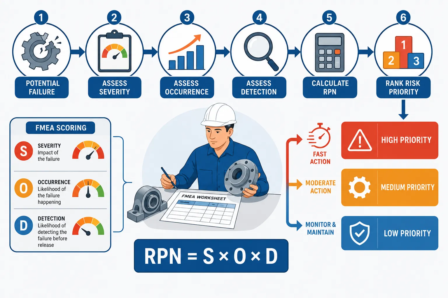
Key Definitions and Concepts
| Term | Definition | Application in Mechanical QA/QC |
|---|---|---|
| FMEA | A structured method for identifying potential failure modes, their causes and their effects | Used to assess mechanical design and manufacturing risks |
| Failure mode | The specific way in which a component, process or system may fail | Example: incorrect weld penetration or bearing seizure |
| Failure effect | The consequence resulting from a failure mode | May affect safety, performance, cost or delivery |
| Failure cause | The underlying reason why a failure may occur | Example: incorrect settings or material defects |
| Severity (S) | A rating of the seriousness of the potential effect | Measures the consequence of failure |
| Occurrence (O) | A rating of the likelihood that the failure cause will occur | Measures the probability or frequency of failure |
| Detection (D) | A rating of the likelihood that existing controls will detect the problem before it causes an effect | Measures the strength of current detection controls |
| Risk Priority Number (RPN) | A numerical value calculated from severity, occurrence and detection ratings | Supports risk ranking and prioritisation |
| Recommended action | A planned measure intended to reduce or control the identified risk | May involve prevention, inspection or process improvement |
| Residual risk | The level of risk remaining after controls have been implemented | Used to evaluate control effectiveness |
Understanding the Purpose of FMEA
Why Mechanical Risks Must Be Prioritised
Mechanical engineering projects often involve multiple systems, components and manufacturing activities operating at the same time. A QA/QC team may identify dozens or even hundreds of potential failure modes during design reviews, production planning or manufacturing inspections.
Without a structured prioritisation method, organisations may:
Focus on minor problems while serious risks remain uncontrolled
Allocate resources inefficiently
Rely on individual opinions rather than evidence
Respond reactively after failures occur
Miss interactions between process weaknesses
Apply inconsistent levels of inspection
FMEA supports a more organised approach by examining each potential failure and assigning ratings based on agreed criteria.
The primary purpose is to answer three important questions:
How serious would the consequence be if the failure occurred?
How likely is the failure or its cause to occur?
How likely is the current control system to detect the problem?
These questions provide the basis for risk prioritisation.
FMEA as a Preventive Quality Tool
FMEA is primarily preventive. It aims to identify potential problems before they become actual non-conformities, equipment failures or safety incidents.
A proactive FMEA process helps teams to:
Anticipate possible failures
Understand the causes of failures
Evaluate existing controls
Strengthen preventive measures
Improve inspection planning
Support engineering decision-making
Reduce rework and waste
The process encourages teams to move beyond the question, “What has gone wrong?” and instead ask, “What could go wrong, why might it happen and how can we prevent it?”
Types of FMEA Relevant to Mechanical Engineering
Design FMEA
Design FMEA focuses on risks associated with the design of a product, component or mechanical system.
It may examine:
Material selection
Load capacity
Component geometry
Tolerance requirements
Environmental conditions
Thermal effects
Wear mechanisms
Corrosion risks
Accessibility for maintenance
A Design FMEA is normally performed during the engineering and design stages, before manufacturing begins.
Process FMEA
Process FMEA focuses on potential failures arising during manufacturing, fabrication, assembly or testing.
Typical areas include:
Material handling
Machining
Forming
Welding
Heat treatment
Assembly
Surface preparation
Testing
Inspection
Process FMEA is particularly important for QA/QC Mechanical Engineering because it examines how manufacturing activities can introduce defects or variation.
Equipment and System FMEA
FMEA can also be applied to equipment and operational mechanical systems.
Examples include:
Pumps
Compressors
Gearboxes
Conveyors
Pressure systems
Rotating machinery
The analysis may identify possible equipment failures and support maintenance or reliability planning.
The Three Main Components of the RPN
Severity Rating
Severity measures the seriousness of the potential effect if the failure occurs.
A severity rating should consider the consequences for:
Personnel safety
Mechanical integrity
Product performance
Environmental protection
Regulatory compliance
Customer requirements
Project delivery
A low severity rating may represent a minor issue with limited operational impact. A high severity rating may represent a failure that could cause serious injury, major equipment damage or critical loss of function.
Typical Severity Considerations
Severity assessments may include the following general principles:
Low severity: minor effect with little influence on function or quality
Moderate severity: noticeable reduction in performance requiring correction
High severity: major functional failure or significant project impact
Very high severity: serious safety, legal or operational consequences
The exact scoring scale should be defined by the organisation or project.
Occurrence Rating
Occurrence measures how likely the failure cause is to happen.
The rating should be based on evidence wherever possible.
Useful sources of evidence include:
Historical failure data
Inspection records
Non-conformity reports
Process capability information
Maintenance history
Supplier performance
Engineering experience
A high occurrence rating may indicate that the cause is frequent or that the process is poorly controlled.
Factors that may increase occurrence include:
Manual operations
Complex manufacturing steps
Inadequate training
Unstable equipment
Poor material control
Frequent process changes
Unclear procedures
Detection Rating
Detection measures the ability of existing controls to identify the failure or its cause before it creates a serious consequence.
Detection is frequently misunderstood. A low detection rating generally represents strong detection capability, while a high rating represents a weak ability to detect the problem. The exact convention should always follow the approved FMEA scoring system being used.
Examples of strong detection controls may include:
Automated monitoring
Validated testing
Independent inspection
Calibrated measurement systems
Mandatory hold points
Examples of weak detection controls may include:
Reliance on final visual inspection
Infrequent sampling
Informal operator checks
Missing inspection records
Calculating the Risk Priority Number
The Basic Formula
The traditional RPN calculation is:
RPN = S × O × D
Where:
S = Severity rating
O = Occurrence rating
D = Detection rating
For example, consider a manufacturing failure mode with the following ratings:
Severity = 8
Occurrence = 5
Detection = 6
The calculation is:
RPN = 8 × 5 × 6
RPN = 240
The calculated value can then be compared with other identified risks.
Understanding the Meaning of the RPN
The RPN is useful because it combines three important aspects of risk into a single numerical value. However, it does not provide an absolute measure of safety or quality.
Two risks may have similar RPN values but require different management decisions.
For example:
Risk A: S = 10, O = 2, D = 4
RPN = 80
Risk B: S = 5, O = 6, D = 6
RPN = 180
Risk B has a higher RPN. However, Risk A has an extremely high severity rating. If the potential consequence involves serious injury or catastrophic equipment failure, it may still require immediate action.
Therefore:
RPN supports prioritisation.
Severity must never be ignored.
Professional judgement remains essential.
Project-specific acceptance criteria must be followed.
A Structured FMEA Process for Mechanical Risks
Step 1: Define the Scope
The team must first define what system, process or activity will be analysed.
The scope may include:
A complete mechanical system
A manufacturing process
A specific component
An assembly operation
A testing activity
Clear boundaries help ensure that the FMEA remains focused.
Step 2: Break the Process into Activities
The process should be divided into logical steps.
For example, a fabrication process may include:
Material receiving
Material verification
Cutting
Preparation
Fit-up
Welding
Inspection
Testing
Final release
Each activity can then be analysed for potential failure modes.
Step 3: Identify the Intended Function
Before identifying failure, the team must understand what each component or process is expected to achieve.
Questions may include:
What is the intended output?
What quality requirements apply?
What performance is required?
What conditions will the component experience?
Without a clear understanding of the intended function, failure cannot be evaluated effectively.
Step 4: Identify Potential Failure Modes
The team should identify the possible ways in which the process or component could fail.
Examples include:
Incorrect dimensions
Material mix-up
Surface damage
Misalignment
Incomplete joining
Excessive wear
Leakage
Mechanical fracture
Test failure
Each failure mode should be described clearly and specifically.
Step 5: Identify Potential Effects
The team should consider what happens if the failure occurs.
Possible effects include:
Reduced mechanical performance
Assembly failure
Equipment downtime
Product rejection
Safety hazards
Project delays
The severity rating is based on the potential effect.
Step 6: Identify Potential Causes
A failure mode can have several possible causes.
Common causes include:
Incorrect procedure
Operator error
Equipment malfunction
Material defects
Inadequate maintenance
Incorrect settings
Poor environmental conditions
Identifying causes is essential because corrective action should address the cause rather than only the visible symptom.
Step 7: Identify Existing Controls
The team should document current preventive and detection controls.
Preventive controls may include:
Approved procedures
Training
Equipment maintenance
Material controls
Detection controls may include:
Inspection
Testing
Measurement
Independent verification
Step 8: Assign Severity, Occurrence and Detection Ratings
Ratings should be assigned using agreed scoring criteria.
The process should involve appropriate technical personnel rather than relying on a single individual’s judgement.
Step 9: Calculate the RPN
The ratings are multiplied:
RPN = S × O × D
The results are recorded and used to rank identified risks.
Step 10: Prioritise Action
High-priority risks should receive appropriate attention.
Possible actions include:
Process redesign
Additional controls
Improved training
Increased inspection
Equipment improvement
Material verification
Independent review
Step 11: Reassess the Risk
After actions have been implemented, the FMEA should be reviewed.
The team should:
Confirm action completion
Evaluate effectiveness
Update occurrence ratings if appropriate
Update detection ratings where controls have improved
Recalculate the RPN
This demonstrates whether the action has genuinely reduced the risk.
Practical Example: Welding Process FMEA
Consider a mechanical fabrication project involving critical welded components.
A potential failure mode is incomplete weld fusion.
Potential Effects
Possible effects include:
Reduced joint strength
Mechanical failure during service
Product rejection
Increased repair costs
Potential Causes
Possible causes may include:
Incorrect welding parameters
Poor joint preparation
Inadequate operator technique
Contaminated surfaces
Existing Controls
Existing controls may include:
Approved welding procedures
Qualified personnel
Visual inspection
Non-destructive testing
The FMEA team may assign ratings based on the approved scoring criteria.
For example:
Severity = 9
Occurrence = 4
Detection = 5
The calculation is:
RPN = 9 × 4 × 5 = 180
The team may decide that the risk requires additional controls.
Possible actions could include:
Improved fit-up verification
Enhanced parameter monitoring
Additional inspection at critical stages
Targeted competence review
After implementing improvements, the occurrence or detection rating may be reduced if evidence demonstrates that the control is more effective.
Professional Tools Used with FMEA
Process Flow Diagrams
A process flow diagram provides a visual representation of the manufacturing sequence.
It helps teams identify:
Process boundaries
Inputs and outputs
Inspection stages
Handover points
Potential control gaps
A well-developed process flow should normally be created before completing a detailed Process FMEA.
Cause-and-Effect Analysis
Cause-and-effect analysis helps teams investigate possible sources of failure.
Common categories may include:
People
Machines
Materials
Methods
Measurement
Environment
This structured approach helps prevent the FMEA team from focusing only on obvious causes.
Risk Registers
FMEA results may be transferred into a broader project risk register.
The risk register may include:
Risk description
Responsible person
Priority level
Required action
Target completion date
Review status
Inspection and Test Plans
FMEA findings can influence Inspection and Test Plans (ITPs).
High-risk activities may require:
Hold points
Witness points
Increased inspection
Additional testing
Benefits of Using RPN in Mechanical QA/QC
Improved Prioritisation
The RPN provides a structured method for comparing multiple risks.
This helps teams to:
Focus on significant risks
Allocate resources effectively
Plan corrective actions
Avoid treating every issue as equally urgent
Better Preventive Action
FMEA encourages preventive thinking.
Instead of waiting for a non-conformity, teams can:
Identify failure modes
Strengthen controls
Improve procedures
Reduce recurrence
Improved Cross-Functional Communication
FMEA normally involves several professional disciplines.
Participants may include:
Design engineers
Mechanical engineers
QA/QC personnel
Production supervisors
Inspectors
Maintenance personnel
This encourages technical discussion and improves shared understanding.
Stronger Documentation
A completed FMEA provides a documented record of risk analysis and decision-making.
It may demonstrate that the organisation has:
Identified foreseeable risks
Evaluated potential consequences
Considered existing controls
Planned improvements
Common Errors When Calculating RPN
Treating the RPN as the Only Decision Criterion
A high RPN is important, but it is not the only factor.
A lower RPN with very high severity may require urgent attention.
Professional practice should therefore consider:
Severity
Regulatory requirements
Safety implications
Client requirements
Engineering judgement
Inconsistent Scoring
FMEA becomes unreliable when different team members interpret scoring scales differently.
To reduce inconsistency:
Use approved rating definitions
Provide scoring guidance
Use evidence where possible
Conduct cross-functional reviews
Confusing Prevention and Detection Controls
Prevention controls reduce the likelihood of a failure occurring.
Detection controls increase the likelihood of identifying a failure.
For example:
Training may help prevent operator errors.
Inspection may help detect errors.
Both are important but serve different purposes.
Reducing Scores Without Evidence
Risk ratings should not be reduced simply because an action has been planned.
A score should be reconsidered only when:
The action has been implemented
The control is operating
Evidence supports improved performance
Professional Judgement When Ranking Mechanical Risks
Considering Severity Separately
High-severity risks require careful consideration even when occurrence is low.
Examples may include potential:
Serious injury
Major equipment failure
Loss of containment
Critical structural failure
Such risks should be escalated according to organisational and project requirements.
Considering Regulatory and Client Requirements
Some risks require mandatory controls regardless of their calculated RPN.
For example, project specifications may require:
Specific testing
Independent inspection
Formal approval
Documented verification
The FMEA process must therefore operate alongside applicable legal, contractual and technical requirements.
Scenario-Based Example: Material Identification Risk
A manufacturing facility receives several visually similar metal materials for different mechanical components.
The FMEA identifies a failure mode:
Incorrect material issued for fabrication.
Potential causes include:
Similar appearance
Poor labelling
Storage errors
Potential effects include:
Reduced component performance
Failure to meet specification
Costly rework
Existing controls include basic visual identification.
The team determines that detection is weak because the incorrect material may not be identified until later testing.
A possible improvement plan includes:
Clear material identification
Controlled storage zones
Traceability verification before issue
Independent checks for critical materials
The revised control system should then be assessed using evidence to determine whether occurrence or detection capability has improved.
Integrating FMEA into Continuous Improvement
FMEA should not be treated as a document completed once and stored away. It should be reviewed when significant changes occur.
Triggers for review may include:
Design modifications
Process changes
New equipment
Material substitutions
Repeated non-conformities
Significant audit findings
Regular review enables the organisation to keep its risk analysis relevant to current operations.
Key Practices for Learners
When calculating and using RPN values, Learners should remember to:
Define the scope clearly.
Understand the intended function of the system or process.
Identify realistic failure modes.
Analyse both effects and causes.
Record existing controls accurately.
Use agreed scoring criteria.
Calculate RPN consistently.
Rank risks to support prioritisation.
Consider high severity independently.
Assign clear actions and responsibilities.
Review the effectiveness of implemented controls.
Update the FMEA when conditions change.
Conclusion
Failure Mode and Effects Analysis provides a structured and professional method for identifying, evaluating and prioritising mechanical risks. By analysing potential failure modes, their effects, causes and existing controls, QA/QC and engineering teams can make more informed decisions about where immediate attention is required.
The Risk Priority Number, calculated by multiplying Severity, Occurrence and Detection ratings, provides a useful method for comparing potential risks. However, the RPN should never replace professional judgement. High-severity failures, legal requirements, project specifications and safety implications must also be considered when determining priorities.
An effective FMEA process requires accurate technical information, consistent scoring, cross-functional involvement and evidence-based review. When used correctly, it helps organisations focus resources on the most significant weaknesses, improve preventive controls, strengthen inspection strategies and reduce the likelihood of costly mechanical failures.
For mechanical engineering and manufacturing professionals, the most important principle is that risk assessment should lead to meaningful action. Calculating an RPN is only one stage of the process. The real value of FMEA is achieved when identified risks are prioritised, appropriate controls are implemented, effectiveness is verified and the analysis is continually updated as designs, processes and operating conditions change.
3.Implement Practical Mitigation Actions to Reduce Identified Production Risks to an Acceptable Level
Risk identification and assessment are only effective when they lead to appropriate action. Once mechanical risks have been identified and prioritised through methods such as Failure Mode and Effects Analysis (FMEA), risk assessment matrices, inspections or engineering reviews, the next stage is to implement practical mitigation measures. Risk mitigation involves selecting, applying and monitoring controls that reduce either the likelihood of a failure occurring, the severity of its consequences, or the possibility that the failure will remain undetected.
Within mechanical engineering and manufacturing, mitigation actions may include additional inspection, improved process controls, preventive maintenance, personnel training, engineering modifications and additional non-destructive testing (NDT). The purpose is not necessarily to eliminate every possible risk, as complete elimination may not always be technically or practically achievable. Instead, the objective is to reduce identified risks to a level that is acceptable according to applicable safety requirements, technical standards, project specifications and organisational risk criteria.
A practical mitigation strategy must be proportionate to the level and nature of the risk. Applying unnecessary controls to every activity can increase cost and delay without improving meaningful quality. Conversely, weak controls on critical activities can allow serious defects to progress through production. Effective QA/QC therefore requires professional judgement when selecting controls.
This section explains how mechanical engineering teams can convert risk assessment findings into practical actions, including the use of additional NDT, enhanced inspection points, process improvements, engineering controls and verification activities.
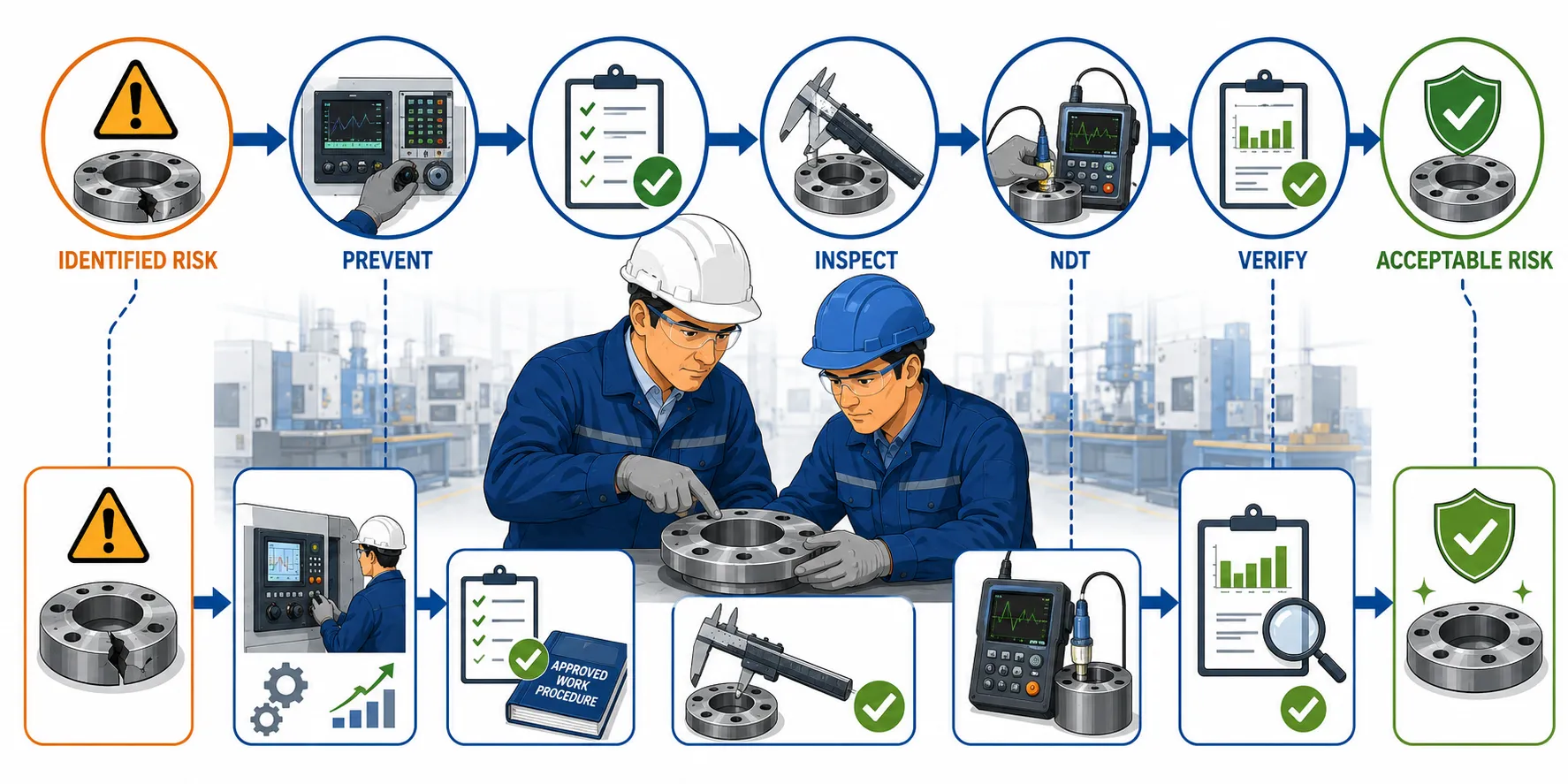
Key Definitions and Concepts
| Term | Definition | Practical Application |
|---|---|---|
| Risk mitigation | The process of reducing the likelihood or consequences of an identified risk | Used to control mechanical and manufacturing risks |
| Preventive control | A measure designed to stop a failure or defect from occurring | Training, approved procedures and equipment controls |
| Detection control | A measure designed to identify a defect before it causes further consequences | Inspection, testing and NDT |
| Residual risk | The level of risk remaining after mitigation measures have been applied | Used to determine whether controls are adequate |
| NDT | A group of testing methods used to examine materials or components without causing unacceptable damage | Supports detection of hidden defects |
| Corrective action | Action taken to address the cause of an identified non-conformity | Prevents recurrence |
| Containment action | Immediate action used to control potentially affected products or processes | Prevents further use or release of suspect items |
| Critical control point | A stage where control is essential to prevent or detect a significant failure | Often included within an ITP |
| Verification | Confirmation through objective evidence that a requirement or control has been fulfilled | Confirms mitigation effectiveness |
Understanding Risk Mitigation in Mechanical Production
From Risk Identification to Practical Action
A risk register or FMEA is only useful when the information it contains is translated into operational decisions. Once a significant failure mode has been identified, the engineering or QA/QC team must decide what action will provide the most effective control.
The mitigation process should answer the following questions:
What is the identified failure or risk?
What is the underlying cause?
What consequences could occur?
Which existing controls are insufficient?
Can the risk be eliminated?
Can the likelihood of occurrence be reduced?
Can the failure be detected earlier?
Who is responsible for implementing the action?
How will effectiveness be verified?
A mitigation action should be linked directly to the identified risk. Generic actions that do not address the actual cause or weakness may create paperwork without improving performance.
The Main Approaches to Risk Mitigation
Mechanical production risks can generally be managed through several approaches.
Elimination
Elimination removes the source of the risk completely.
Examples may include:
Removing an unnecessary hazardous manufacturing activity
Eliminating a known failure-prone component
Replacing an unsuitable production method
Elimination is often the most effective option where technically possible.
Substitution
Substitution involves replacing a high-risk material, component or process with a safer or more reliable alternative.
Examples include:
Selecting a more suitable material
Using a more stable manufacturing method
Replacing unreliable equipment
The replacement itself must be evaluated to ensure that it does not introduce new risks.
Engineering Controls
Engineering controls modify equipment, processes or physical systems to reduce risk.
Examples include:
Automated process monitoring
Improved fixtures
Equipment interlocks
Temperature control systems
Mechanical guarding
These controls can reduce dependence on individual human performance.
Administrative Controls
Administrative controls establish requirements for how work should be performed.
They may include:
Standard operating procedures
Work instructions
Inspection plans
Competence requirements
Approval systems
Administrative controls are important but may be less reliable when used alone for critical risks.
Detection Controls
Detection controls identify problems before defective work progresses further.
Examples include:
Visual inspection
Dimensional measurement
Functional testing
Pressure testing
Non-destructive testing
Selecting the Most Appropriate Mitigation Action
Match the Control to the Failure Cause
An effective mitigation action should address the real cause of the identified risk.
For example, consider a repeated dimensional defect caused by worn machining equipment. Increasing final inspection may detect more defective components, but it does not prevent the defect from occurring.
A more effective strategy may include:
Inspecting tool condition
Establishing replacement criteria
Introducing preventive maintenance
Monitoring machine performance
This illustrates an important principle: prevention is generally preferable to relying only on detection.
Consider the Consequences of Failure
The seriousness of potential consequences should influence the strength of the mitigation.
High-consequence risks may require:
Multiple independent controls
Enhanced inspection
Specialist technical review
Mandatory hold points
Additional testing
Lower-risk activities may require routine process controls.
Consider the Ability to Detect the Failure
Some defects are easy to identify through normal inspection. Others remain hidden until advanced testing is performed.
A mitigation strategy should consider:
Whether the defect is visible
Whether it can be measured
When it can be detected
What testing method is suitable
Whether inspection is possible after assembly
If a defect cannot be detected during final inspection, earlier process controls may be necessary.
The Role of Additional Non-Destructive Testing
What Is Non-Destructive Testing?
Non-destructive testing refers to examination methods that provide information about a component or material without causing unacceptable damage to its intended function.
NDT is particularly valuable where defects may exist below the surface or within a component and cannot be identified through visual inspection alone.
Depending on the component and applicable requirements, NDT methods may include:
Visual testing
Liquid penetrant testing
Magnetic particle testing
Ultrasonic testing
Radiographic testing
Other specialised examination techniques
The selection of an NDT method must be based on the material, geometry, expected defect type and applicable technical requirements.
Why Additional NDT May Be Required
Additional NDT may be introduced when the risk assessment identifies a weakness in existing detection controls.
Examples include:
Increased inspection coverage for critical joints
Additional examination after process changes
Expanded testing following recurring defects
Increased sampling where risk has risen
Additional verification after repairs
The objective is to improve confidence that unacceptable defects are identified before release.
NDT as a Detection Control
It is important to understand that NDT is generally a detection measure rather than a preventive measure. Testing can identify a defect, but it does not necessarily stop the defect from being created.
For this reason, a strong mitigation strategy may combine:
Prevention of the defect
Detection of the defect
Verification of the effectiveness of controls
For example, a welding-related risk may be managed through:
Qualified procedures
Competent personnel
Controlled parameters
Fit-up inspection
Appropriate NDT
This creates multiple layers of control.
Common NDT Approaches in Risk Mitigation
Visual Testing
Visual examination is one of the most common inspection methods.
It may identify:
Surface damage
Incorrect assembly
Visible discontinuities
Poor workmanship
Obvious dimensional issues
Visual testing is useful but has limitations.
Potential limitations include:
Internal defects cannot be seen directly.
Results may depend on inspector competence.
Access and lighting can affect examination quality.
Liquid Penetrant Testing
Liquid penetrant testing is generally used to identify certain surface-breaking discontinuities in suitable non-porous materials.
It may support the detection of:
Surface cracks
Surface-breaking defects
Certain discontinuities
The method requires appropriate preparation, application and evaluation procedures.
Magnetic Particle Testing
Magnetic particle testing may be suitable for identifying certain surface and near-surface discontinuities in appropriate ferromagnetic materials.
Its application depends on:
Material properties
Component geometry
Testing requirements
The method should be selected and performed in accordance with approved procedures and applicable requirements.
Ultrasonic Testing
Ultrasonic testing uses sound energy to examine materials and identify certain internal features or discontinuities.
It may support risk mitigation where:
Internal examination is required
Component thickness is significant
Early detection of internal defects is important
The reliability of results depends on equipment suitability, procedure requirements and operator competence.
Radiographic Testing
Radiographic testing can provide information about certain internal conditions by using appropriate imaging methods.
It may be used where technical requirements call for examination of internal features.
Because specialised equipment and safety controls may be required, testing must be planned and performed by suitably authorised and competent personnel.
Developing a Practical Mitigation Plan
Step 1: Review the Identified Risk
The mitigation process begins by reviewing the risk assessment information.
The team should confirm:
The failure mode
The potential cause
The expected consequences
The existing controls
The current risk priority
Poorly defined risks can result in poorly designed mitigation actions.
Step 2: Determine the Root or Contributing Causes
A mitigation plan should address causes rather than symptoms wherever possible.
Useful methods may include:
Root cause analysis
Process review
Cause-and-effect analysis
Technical investigation
Review of historical records
Potential contributing factors may include:
Personnel competence
Equipment condition
Material variation
Procedure weaknesses
Environmental conditions
Step 3: Identify Available Control Options
The team should consider several possible mitigation options.
These may include:
Engineering redesign
Improved material controls
Additional process monitoring
Increased inspection
Additional NDT
Preventive maintenance
Competence development
Improved work instructions
Selecting from multiple options helps ensure that the chosen action is appropriate.
Step 4: Evaluate Practicality and Effectiveness
Each potential action should be evaluated.
Important considerations include:
Expected reduction in risk
Technical feasibility
Effect on production
Required resources
Cost
Time requirements
Applicable standards
The cheapest option is not always the most effective option.
Step 5: Assign Responsibilities
Every mitigation action should have a clearly identified responsible person or function.
Responsibilities may involve:
Engineering
Production
QA/QC
Maintenance
Project management
Unclear ownership is a common reason why corrective actions remain incomplete.
Step 6: Establish Verification Requirements
The organisation must determine how it will confirm that the action has worked.
Verification may include:
Repeat inspection
NDT results
Process monitoring
Audit
Performance data
Using Inspection and Test Plans to Support Mitigation
Introducing Additional Inspection Points
Inspection and Test Plans can be revised when risk assessments identify significant process weaknesses.
Additional controls may include:
Increased inspection frequency
Additional verification stages
Hold points
Witness points
Independent inspection
The additional requirements should be justified by risk and clearly communicated.
Hold Points
A hold point is a stage where work cannot proceed until the required inspection or approval has been completed.
Hold points may be appropriate where:
A critical activity will become inaccessible later
A significant safety or quality risk exists
Client approval is required
Regulatory requirements apply
Witness Points
A witness point provides an opportunity for designated personnel to observe an activity or inspection.
It may support:
Transparency
Independent verification
Project confidence
The exact application should follow the approved project requirements.
Practical Example: Mitigating a Welding Production Risk
A mechanical manufacturing team identifies a significant risk involving possible internal discontinuities in critical welded joints.
The existing control system includes:
Approved welding procedures
Qualified personnel
Visual inspection
The FMEA indicates that visual inspection alone may not provide adequate detection capability for certain internal conditions.
The mitigation plan may include:
Reviewing welding parameters
Strengthening fit-up controls
Introducing additional NDT at identified critical locations
Reviewing inspector competence
Establishing clearer acceptance criteria
The team should then verify whether these actions have improved risk control.
Evidence may include:
Reduced defect trends
Improved inspection results
Successful audit findings
Recalculated risk assessment values
Practical Example: Material-Related Production Risk
A manufacturing facility identifies repeated damage to materials caused by poor storage conditions.
The potential consequences include:
Material deterioration
Reduced product quality
Rework
A mitigation plan may include:
Defined storage areas
Improved material identification
Environmental controls
Routine condition inspections
Additional NDT may not be the appropriate primary control because the root cause is related to material handling and storage.
This example demonstrates the importance of selecting controls that match the actual source of risk.
Monitoring Residual Risk
What Is Residual Risk?
Residual risk is the level of risk that remains after mitigation actions have been implemented.
Risk can be reassessed by considering whether:
Severity has changed
Occurrence has been reduced
Detection capability has improved
The objective is to determine whether the remaining risk is acceptable according to the project’s risk criteria.
Acceptable Risk Levels
Acceptability should not be determined informally.
The organisation should consider:
Legal obligations
Project specifications
Technical standards
Safety requirements
Internal risk criteria
A risk may require further action even after an RPN reduction if serious consequences remain possible.
Verifying the Effectiveness of Mitigation Measures
Action Completion Is Not the Same as Effectiveness
A common mistake is to close a risk action because the planned activity has been completed.
For example, completing additional NDT does not automatically prove that the overall process risk has been reduced.
The team should evaluate:
Whether the testing method was appropriate
Whether defects were identified
Whether the root cause was addressed
Whether similar failures continue
Objective Evidence
Effective verification should be based on objective evidence.
Examples include:
Inspection reports
Test results
NDT records
Calibration records
Audit findings
Process performance data
Objective evidence supports defensible professional decisions.
Documentation of Risk Mitigation
Maintaining a Risk Action Record
A mitigation record should normally include:
Risk identification number
Description of the risk
Current controls
Required mitigation action
Responsible person
Target date
Verification method
Completion status
This creates traceability and accountability.
Updating FMEA Records
After effective action has been implemented, the FMEA should be reviewed.
The review may include:
Updated controls
Revised ratings
Revised RPN
Evidence of effectiveness
The original risk history should normally remain traceable.
Key Benefits of Practical Risk Mitigation
Improved Mechanical Reliability
Effective mitigation reduces the likelihood of failures reaching the operational stage.
Benefits include:
Improved component performance
Reduced downtime
Better system reliability
Reduced Rework and Waste
Early risk controls can prevent defects from progressing.
This can reduce:
Scrap
Repair work
Material waste
Production delays
Improved Safety
Risk mitigation can reduce exposure to:
Equipment failures
Unsafe processes
Mechanical hazards
Stronger Quality Assurance
Practical mitigation strengthens the connection between risk assessment and operational control.
It supports:
Better inspection planning
Improved documentation
More consistent production
Common Mistakes When Implementing Mitigation Actions
Adding Inspection Without Addressing the Cause
Additional inspection can identify defects but may not prevent them.
Where possible, the team should also address:
Process instability
Equipment issues
Training gaps
Procedure weaknesses
Using NDT Without a Clear Technical Justification
NDT should be selected based on the identified risk.
Teams should consider:
Expected defect type
Material properties
Component geometry
Applicable requirements
Testing should not be increased simply because it appears to be a stronger control.
Failing to Verify Competence
Additional testing is only effective when performed and interpreted by competent personnel in accordance with applicable procedures and requirements.
Important considerations include:
Personnel competence
Equipment suitability
Approved procedures
Proper documentation
Closing Actions Too Early
A mitigation action should not be considered fully effective until objective evidence demonstrates that the intended control has been achieved.
Professional Responsibilities in Risk Mitigation
QA/QC personnel have an important role in ensuring that risk assessments lead to meaningful improvements.
Professional responsibilities include:
Reviewing risk assessment findings
Supporting the selection of suitable controls
Ensuring inspection activities are properly planned
Verifying evidence
Escalating significant unresolved risks
Engineering and production teams must also participate because effective mitigation usually requires cross-functional cooperation.
Key Points for Learners
When implementing practical mitigation actions, Learners should remember that:
Risk mitigation must follow identified risks and causes.
Prevention is generally stronger than relying only on detection.
Additional NDT may improve detection of hidden defects.
The NDT method must match the material and expected risk.
High-risk activities may require multiple layers of control.
Inspection and Test Plans should reflect significant risks.
Responsibilities and deadlines must be clearly assigned.
Residual risk must be assessed after action.
Completed actions must be verified using objective evidence.
Risk mitigation records must remain traceable.
Conclusion
Implementing practical mitigation actions is the stage at which risk assessment becomes operational improvement. Mechanical and manufacturing risks must be managed through controls that are technically appropriate, proportionate and capable of addressing the identified causes and consequences.
Additional non-destructive testing can provide an important detection control where hidden defects present a significant production risk. However, NDT should not be treated as a universal solution. The most effective risk mitigation strategies combine preventive controls, process improvements and appropriate detection methods.
A structured approach involves reviewing the identified risk, understanding its causes, selecting suitable controls, assigning responsibilities and verifying effectiveness. Inspection plans, hold points, process monitoring and additional testing can all support this process when applied appropriately.
The final objective is to reduce residual risk to an acceptable level while maintaining compliance with applicable technical, safety and quality requirements. Through systematic mitigation and evidence-based verification, QA/QC and mechanical engineering teams can reduce defects, improve reliability, protect personnel and support successful manufacturing outcomes.