
Lesson no 6 :Analyse environmental and load impacts on mechanical systems for QA/QC purposes.
Mechanical systems operate under a wide range of environmental conditions and loading situations that can significantly influence their performance, reliability, safety, and service life. For QA/QC professionals, understanding these influences is essential when assessing whether mechanical components and systems meet specified quality, performance, and safety requirements. The lesson “Analyse Environmental and Load Impacts on Mechanical Systems for QA/QC Purposes” develops Learners’ understanding of how external environmental conditions and applied loads can affect mechanical integrity and quality throughout the operational lifecycle.
Environmental factors may include temperature variations, humidity, moisture, corrosive atmospheres, chemicals, dust, vibration, radiation, and exposure to marine or industrial environments. These conditions can contribute to corrosion, material degradation, thermal expansion, embrittlement, fatigue, wear, and other forms of deterioration. QA/QC professionals need to recognise these potential effects when reviewing material specifications, inspection requirements, testing procedures, maintenance records, and quality documentation.
Mechanical systems are also exposed to different types of loads, including tensile, compressive, shear, bending, torsional, impact, thermal, and cyclic loads. Excessive, repeated, or improperly distributed loading can lead to deformation, cracking, fatigue failure, component distortion, or premature deterioration. Understanding these loading conditions enables Learners to assess whether components have been manufactured, inspected, tested, and installed in accordance with defined specifications and applicable quality requirements.
The lesson also considers the relationship between environmental conditions and mechanical loading. In many engineering applications, these factors act simultaneously and can accelerate material degradation or component failure. For example, cyclic loading combined with a corrosive environment may increase the risk of fatigue and corrosion-related damage. Temperature fluctuations combined with mechanical stress can also affect dimensional stability and material performance.
From a QA/QC perspective, analysing these impacts supports effective inspection planning, risk identification, acceptance decisions, and defect prevention. Learners will explore how environmental and loading conditions can influence inspection frequency, material selection, testing requirements, component protection, and quality control measures. The lesson therefore provides an important foundation for evaluating mechanical system integrity and supporting reliable engineering performance through systematic QA/QC practices.
1.Analyse How External Environmental Factors Impact the Degradation Rates of Mechanical Systems
Mechanical systems are designed to operate within defined environmental and loading conditions. However, exposure to external environmental factors can gradually alter the physical, chemical, mechanical, and functional properties of materials and components. In quality assurance and quality control (QA/QC), understanding these environmental influences is essential because degradation may begin long before a visible failure occurs. A mechanical component can remain apparently functional while corrosion, material deterioration, surface damage, dimensional change, fatigue acceleration, or loss of protective properties is already taking place.
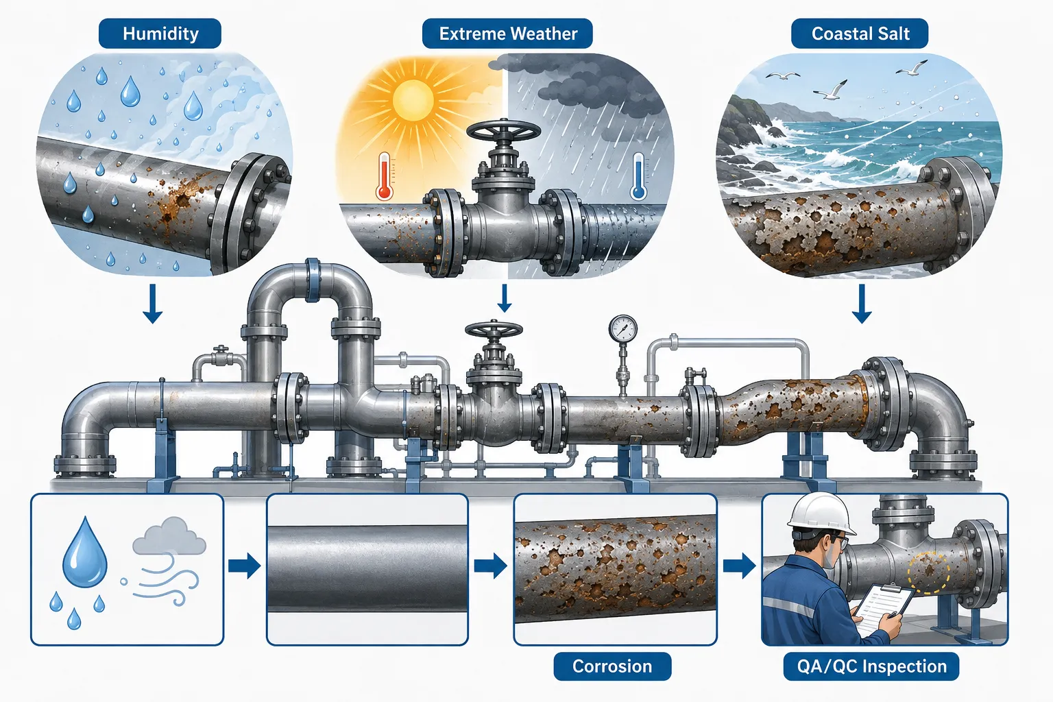
Environmental degradation refers to the progressive deterioration of a material or mechanical component caused by its surrounding conditions. Factors such as ambient humidity, temperature, rainfall, condensation, airborne contaminants, industrial chemicals, ultraviolet radiation, dust, and coastal salt exposure can influence the rate and nature of degradation. The severity of the effect depends on the material, environmental exposure, duration, operating conditions, protective systems, component design, and quality of maintenance.
For a QA/QC professional, environmental analysis is therefore not simply an operational consideration. It is part of quality planning, material selection, inspection strategy, risk assessment, preservation, testing, and acceptance decisions. Understanding environmental degradation allows quality personnel to determine where deterioration is most likely to occur, what controls should be implemented, and what evidence should be retained to demonstrate that the required quality level has been achieved.
Understanding Environmental Degradation in Mechanical Systems
Environmental degradation occurs when surrounding conditions interact with a material or component and progressively reduce its required properties or performance. The deterioration may be physical, chemical, electrochemical, thermal, or a combination of several mechanisms.
A mechanical system may contain carbon steel, stainless steel, aluminium alloys, copper alloys, polymers, elastomers, coatings, seals, lubricants, insulation materials, and other components. Each material responds differently to environmental exposure. Therefore, QA/QC controls cannot be based on environmental conditions alone; they must consider the interaction between the environment and the specific material or component.
Definition of Environmental Degradation
Environmental degradation can be defined as the progressive deterioration of a material, component, protective coating, or mechanical system caused by exposure to environmental conditions that adversely affect its properties, integrity, reliability, or service performance.
Common consequences include:
Corrosion and oxidation
Surface deterioration
Loss of protective coating performance
Material embrittlement
Cracking
Pitting
Erosion
Wear acceleration
Swelling or dimensional changes
Loss of mechanical strength
Deterioration of seals and elastomers
Lubricant degradation
Electrical or instrumentation-related deterioration in associated systems
Reduced service life
Increased probability of mechanical failure
The role of QA/QC is to understand these mechanisms and establish appropriate controls before degradation becomes a significant quality or reliability problem.
Key Environmental Factors Affecting Mechanical Degradation
External environmental conditions rarely act independently. A mechanical system may experience humidity, salt, temperature changes, contamination, and mechanical loading simultaneously. The combined effect can be significantly more damaging than an individual environmental factor.
The following environmental factors are particularly important when assessing mechanical systems.
Ambient Humidity
Humidity refers to the amount of moisture present in the surrounding atmosphere. High humidity can significantly increase the risk of corrosion, particularly for susceptible metallic materials.
When moisture remains on a metal surface, it can provide an electrolyte that enables electrochemical corrosion processes. The risk becomes greater when the surface remains wet for extended periods or when contaminants such as salts or industrial pollutants are present.
Humidity can affect mechanical systems through:
Increased atmospheric corrosion
Formation of surface oxidation
Corrosion beneath coatings
Deterioration of fasteners
Corrosion of joints and connections
Moisture penetration into poorly protected areas
Deterioration of seals and gaskets
Condensation inside equipment
Reduced effectiveness of protective coatings
Increased risk of corrosion under insulation where applicable
Condensation and Moisture Cycling
Humidity becomes particularly significant when temperature changes cause condensation. A surface may be exposed to humid air during the day and then cool below the surrounding air’s dew point, resulting in moisture formation.
This repeated wetting and drying cycle can accelerate degradation because the component is repeatedly exposed to conditions that support corrosion.
QA/QC professionals should therefore consider:
Equipment storage conditions
Temperature variations
Ventilation
Moisture accumulation
Drainage arrangements
Protective packaging
Coating condition
Internal condensation
Moisture-sensitive materials
A component stored in a humid environment may require greater preservation controls than an identical component stored in a dry, controlled environment.
Extreme Weather Conditions
Extreme weather can expose mechanical systems to conditions substantially beyond their normal operating environment. These conditions can influence materials, protective systems, lubrication, dimensional stability, and structural integrity.
Extreme weather may include:
Very high temperatures
Very low temperatures
Heavy rainfall
Flooding
Strong winds
Snow and ice
Storms
Lightning-related environmental effects
Rapid temperature fluctuations
Prolonged drought and dust exposure
Sandstorms
The QA/QC significance depends on the location and intended application of the mechanical system.
High Temperature Exposure
Elevated temperatures can affect mechanical systems by changing material properties and accelerating certain degradation processes. Some materials lose strength at elevated temperatures, while lubricants, seals, polymers, and coatings may deteriorate more rapidly.
Potential effects include:
Reduced material strength
Thermal expansion
Distortion
Oxidation
Lubricant deterioration
Seal degradation
Coating deterioration
Increased creep risk in suitable materials and applications
Accelerated chemical reactions
Reduced component service life
QA/QC professionals should verify that material specifications, component ratings, protective systems, and inspection requirements are appropriate for the anticipated temperature range.
Low Temperature Exposure
Very low temperatures can also influence mechanical performance. Certain materials may become more brittle at low temperatures, increasing their susceptibility to cracking or fracture under mechanical stress.
Potential concerns include:
Increased brittleness
Reduced impact toughness
Thermal contraction
Seal hardening
Lubricant viscosity changes
Cracking of susceptible materials
Differential contraction between dissimilar materials
Reduced flexibility of polymers and elastomers
Where low-temperature operation is expected, QA/QC personnel should ensure that appropriate material specifications and testing requirements have been considered.
Coastal Salt Environments
Coastal and marine environments are particularly important in mechanical QA/QC because airborne salt particles and moisture can create highly corrosive conditions for many metallic materials.
Salt-containing moisture can increase the conductivity of surface moisture and promote electrochemical corrosion. Chloride-containing environments can be particularly aggressive toward susceptible materials and may contribute to localised corrosion mechanisms.
Mechanical systems located near coastlines, offshore facilities, marine terminals, ports, shipyards, and similar environments may therefore require enhanced corrosion protection and inspection controls.
Effects of Salt Exposure
Coastal salt environments may contribute to:
General surface corrosion
Pitting corrosion
Crevice corrosion
Corrosion beneath deposits
Coating breakdown
Fastener deterioration
Corrosion at joints
Galvanic corrosion between dissimilar metals
Reduced wall thickness
Surface roughening
Loss of dimensional accuracy
Reduced component integrity
The presence of salt alone does not determine the degradation rate. Factors such as humidity, temperature, wind, surface contamination, material type, coating quality, drainage, and exposure duration must also be considered.
Environmental Factors and Their QA/QC Significance
| Environmental Factor | Typical Effect on Mechanical Systems | Potential Degradation Mechanism | QA/QC Consideration |
|---|---|---|---|
| High humidity | Moisture retention and corrosion risk | Atmospheric/electrochemical corrosion | Coating inspection, storage control, corrosion monitoring |
| Condensation | Repeated surface wetting | Corrosion, coating deterioration | Ventilation, drainage, preservation and inspection |
| Coastal salt | Increased corrosion activity | Pitting, crevice and galvanic corrosion | Protective coating, material selection, inspection frequency |
| High temperature | Material and lubricant deterioration | Oxidation, thermal degradation, creep | Temperature-rated materials and components |
| Low temperature | Increased brittleness and contraction | Cracking, fracture, seal deterioration | Low-temperature material verification and testing |
| Heavy rainfall | Water exposure and moisture accumulation | Corrosion and coating deterioration | Drainage, sealing and surface protection |
| Flooding | Prolonged water contact and contamination | Corrosion, lubricant contamination, component damage | Post-exposure inspection and preservation |
| Dust and sand | Surface abrasion and contamination | Erosion, wear, blockage | Filtration, sealing and inspection |
| Industrial pollutants | Chemical contamination | Chemical attack and accelerated corrosion | Environmental monitoring and protective systems |
| Temperature cycling | Repeated expansion and contraction | Fatigue, cracking, joint loosening | Inspection of joints, welds and susceptible components |
How Humidity Influences Degradation Rates
The relationship between humidity and degradation rate is important in QA/QC because corrosion does not simply depend on whether the atmosphere is described as “humid” or “dry”. The duration for which a surface remains sufficiently wet can have a major influence on deterioration.
Surface Wetness
A metal surface exposed to humid air may not corrode at the same rate as a surface that remains continuously wet. When moisture forms a persistent film, electrochemical reactions can continue for longer periods.
Factors influencing surface wetness include:
Relative humidity
Temperature
Surface temperature
Condensation
Rainfall
Ventilation
Surface cleanliness
Salt contamination
Dust deposits
Component geometry
Areas where water can collect are particularly important. Horizontal surfaces, crevices, low points, poorly drained sections, and enclosed spaces may retain moisture for longer periods than exposed vertical surfaces.
Humidity and Protective Coatings
Protective coatings are commonly used to isolate metal surfaces from environmental exposure. However, high humidity can contribute to coating deterioration if the coating system is poorly selected, incorrectly applied, damaged, or inadequately maintained.
QA/QC inspection should therefore consider:
Surface preparation
Coating system specification
Coating thickness
Adhesion where required
Surface cleanliness
Application conditions
Visible coating defects
Holidays or discontinuities where applicable
Damage during transportation or installation
Repair of damaged areas
A high-quality coating system can substantially reduce environmental degradation, but coating performance depends on correct specification, application, inspection, and maintenance.
How Coastal Salt Accelerates Corrosion
Salt contamination is particularly significant because dissolved salts can increase the conductivity of surface moisture. This can facilitate electrochemical corrosion processes and make corrosion more persistent.
Wind can transport salt-containing moisture inland from coastal areas. Salt deposits may accumulate on exposed surfaces, particularly where rain does not adequately wash them away.
High-Risk Areas
QA/QC professionals should pay particular attention to:
Bolted connections
Welded joints
Crevices
Flanges
Supports
Drainage points
Undersides of equipment
Coating defects
Exposed fasteners
Dissimilar metal connections
Areas where deposits accumulate
These locations can retain moisture and contaminants and may therefore experience accelerated localised degradation.
Galvanic Effects in Marine Environments
When two dissimilar metals are electrically connected in the presence of an electrolyte such as salt-contaminated water, galvanic corrosion may occur.
The risk depends on:
The materials involved
Their relative electrochemical behaviour
The area relationship between the metals
Environmental conductivity
Exposure conditions
Quality of isolation or protective measures
QA/QC personnel should therefore verify material compatibility where dissimilar materials are used.
Appropriate controls may include:
Material verification
Suitable insulating arrangements
Protective coatings
Appropriate fastener selection
Controlled assembly procedures
Inspection of interfaces
Monitoring of corrosion-prone locations
Environmental Exposure and Mechanical Loading
Environmental degradation becomes more significant when mechanical components are also subjected to repeated or high mechanical loads. A component weakened by corrosion may have reduced resistance to stress.
For example, corrosion can create pits or localised reductions in cross-sectional area. These features may act as stress concentrations. When the component experiences cyclic loading, cracks may initiate and grow more readily.
This interaction demonstrates why QA/QC assessment should not consider environmental conditions and mechanical loading as completely separate issues.
Important combined effects include:
Corrosion combined with cyclic loading
Temperature changes combined with thermal stress
Wear combined with contamination
Moisture combined with fatigue
Salt exposure combined with mechanical stress
High temperature combined with oxidation
Low temperature combined with impact loading
Process for Assessing Environmental Degradation Risk
A systematic QA/QC approach can help determine how environmental conditions may affect mechanical system quality.
Step 1: Identify the Operating Environment
First, establish where and under what conditions the mechanical system will operate.
Consider:
Geographic location
Indoor or outdoor installation
Coastal or inland location
Temperature range
Humidity
Rainfall
Chemical exposure
Dust and sand
Marine exposure
Expected operating duration
Step 2: Identify Materials and Components
Determine which materials and components are present and how they respond to the identified environment.
Review:
Material specifications
Material certificates
Component specifications
Protective coatings
Seal materials
Lubricants
Fasteners
Welded components
Dissimilar material interfaces
Step 3: Identify Potential Degradation Mechanisms
Determine which deterioration mechanisms could reasonably occur.
These may include:
Corrosion
Pitting
Crevice corrosion
Galvanic corrosion
Oxidation
Erosion
Wear
Cracking
Embrittlement
Thermal degradation
Coating failure
Step 4: Assess Severity and Likelihood
QA/QC personnel should evaluate how serious the degradation could be and how likely it is to occur.
Relevant considerations include:
Environmental severity
Exposure duration
Component criticality
Material susceptibility
Existing protective measures
Historical inspection findings
Failure consequences
Accessibility for inspection
Step 5: Establish Appropriate Controls
Controls should be proportionate to the identified environmental risk.
Possible controls include:
Appropriate material selection
Protective coatings
Corrosion-resistant materials
Environmental protection
Sealing
Drainage
Controlled storage
Preservation
Regular inspection
Cleaning
Corrosion monitoring
Non-destructive testing where appropriate
Preventive maintenance
Practical Example: Carbon Steel Equipment in a Coastal Facility
Consider a carbon steel mechanical assembly installed at a coastal industrial facility. The equipment is exposed to high humidity, salt-laden air, temperature variations, and occasional rainfall.
The QA/QC assessment should recognise that these conditions can increase the likelihood of corrosion. Particular attention should be given to coating integrity, fasteners, welded joints, crevices, drainage points, and areas where salt deposits may accumulate.
An appropriate QA/QC approach may include:
Verifying material certificates before installation
Confirming the specified corrosion protection system
Inspecting surface preparation
Checking coating application and thickness
Inspecting for coating damage after transportation
Ensuring damaged areas are repaired correctly
Checking drainage arrangements
Identifying potential water traps
Inspecting corrosion-prone locations periodically
Recording inspection findings
Raising non-conformance reports where specified requirements are not met
Implementing corrective actions where necessary
The objective is not merely to identify visible rust. The objective is to prevent environmental degradation from progressing to a condition that could compromise mechanical integrity.
Practical Example: Mechanical Equipment in a Hot and Dusty Environment
Mechanical equipment operating in a hot and dusty industrial environment may experience elevated temperatures, airborne particles, abrasive contamination, and lubricant degradation.
Potential effects may include:
Increased wear
Abrasion
Lubricant deterioration
Seal degradation
Blockage of ventilation systems
Increased friction
Reduced component life
Surface erosion
QA/QC controls should consider whether equipment specifications, protective systems, seals, filters, lubrication arrangements, and maintenance requirements are appropriate for the environmental conditions.
Key Benefits of Environmental Impact Analysis in QA/QC
Analysing environmental degradation provides several important benefits to mechanical quality management.
Improved Material Selection
Understanding the environment helps quality professionals determine whether the selected material is suitable for the intended application.
Better Inspection Planning
Environmental risk information allows inspection resources to be directed toward areas most susceptible to deterioration.
Reduced Failure Risk
Early identification of environmental degradation mechanisms can help prevent component failure and unplanned downtime.
Improved Reliability
Appropriate environmental controls help mechanical systems maintain their required performance over their intended service life.
Enhanced Traceability
Environmental considerations can be incorporated into inspection records, quality plans, material documentation, maintenance records, and corrective action systems.
Reduced Maintenance Costs
Preventive controls can reduce the need for extensive repairs or premature component replacement.
Improved Safety
Environmental degradation can eventually compromise mechanical integrity. Effective QA/QC controls therefore contribute to safer operation.
Role of the QA/QC Professional
A QA/QC professional should not treat environmental conditions as background information. They should consider environmental exposure as part of the overall quality risk profile of the mechanical system.
Key responsibilities may include:
Reviewing environmental requirements in specifications
Confirming material suitability
Verifying protective systems
Reviewing inspection and test plans
Identifying environmental degradation risks
Ensuring appropriate inspection controls are established
Reviewing inspection findings
Monitoring recurring defects
Supporting root cause analysis
Ensuring non-conformities are appropriately documented
Verifying corrective actions
Maintaining quality records
Supporting continuous improvement
Environmental Degradation and Quality Documentation
Quality documentation provides evidence that environmental risks have been considered and controlled.
Important records may include:
Material certificates
Inspection reports
Coating inspection reports
Environmental condition records where required
Inspection and Test Plans
Non-Conformance Reports
Corrective action records
Maintenance records
Corrosion monitoring reports
Photographic inspection evidence
Component traceability records
Supplier documentation
Final inspection records
Accurate documentation allows organisations to demonstrate that specified quality requirements were considered throughout the mechanical system lifecycle.
Key Concepts for Learners
Learners should understand that environmental degradation is influenced by the interaction between material, environment, exposure duration, component design, protective measures, loading conditions, and maintenance.
The most important concepts include:
Humidity can increase corrosion risk by supporting moisture films on susceptible surfaces.
Condensation can create repeated wetting conditions that accelerate deterioration.
Coastal salt environments can increase the severity of corrosion.
Temperature extremes can alter material and component performance.
Temperature cycling can create repeated expansion and contraction.
Protective coatings require appropriate specification, application, inspection, and maintenance.
Component geometry can create locations where moisture and contaminants accumulate.
Dissimilar metals can create galvanic corrosion risks under suitable conditions.
Environmental degradation can interact with mechanical loading.
Inspection strategies should reflect environmental severity and component criticality.
Environmental conditions should be considered during material selection, storage, installation, operation, and maintenance.
Quality documentation provides evidence of environmental risk control.
Summary
External environmental factors can have a substantial influence on the degradation rate, reliability, and service life of mechanical systems. Ambient humidity, condensation, extreme temperatures, rainfall, industrial contamination, dust, and coastal salt exposure can contribute to corrosion, material deterioration, coating failure, wear, cracking, dimensional changes, and other degradation mechanisms.
For QA/QC professionals, the critical requirement is to understand the relationship between environmental exposure and mechanical integrity. Environmental conditions should be identified during quality planning and evaluated against material characteristics, component design, operating requirements, mechanical loading, protective systems, and inspection requirements.
Humidity and moisture can create conditions for corrosion, while coastal salt can increase the aggressiveness of the environment. Extreme temperatures can alter material properties and accelerate deterioration. When these conditions combine with mechanical loading, the potential for premature degradation can increase further.
A systematic QA/QC approach involves identifying the operating environment, assessing material and component susceptibility, determining potential degradation mechanisms, evaluating risk, implementing suitable controls, and monitoring performance through inspection and quality records.
Ultimately, environmental analysis supports a preventive approach to mechanical quality management. Instead of waiting for visible deterioration or component failure, QA/QC professionals can identify environmental risks early and establish appropriate measures to preserve material integrity, maintain reliability, reduce failures, control maintenance costs, and support the safe and effective operation of mechanical systems.
2.Evaluate the Structural Response of Piping Networks and Support Structures to Dynamic Operational Loads, Vibrations, or Fluid Pressure Shocks
Piping networks are critical mechanical systems used to transport liquids, gases, steam, chemicals, hydrocarbons, and other process fluids across industrial facilities. Their reliability depends not only on the strength of the pipe itself but also on the correct design, fabrication, installation, support, restraint, alignment, and inspection of the complete piping system. During operation, piping networks can be exposed to dynamic forces that vary with time and can produce stresses, displacement, vibration, and fatigue. These effects become particularly important when the system experiences fluctuating flow, rotating equipment, rapid valve operation, pressure surges, or sudden changes in operating conditions.
For QA/QC professionals, evaluating the structural response of piping networks means understanding how pipes, fittings, valves, joints, supports, anchors, guides, and connected equipment respond when subjected to dynamic operational conditions. A piping system that performs adequately under static pressure may behave differently when subjected to repeated vibration or sudden pressure changes. Dynamic loading can cause fatigue, loosening of connections, support damage, excessive displacement, cracking, leakage, and premature component failure if it is not properly controlled.
The purpose of this section is to develop Learners’ understanding of the relationship between dynamic operational loads and piping-system integrity. It focuses on vibration, fluid pressure shocks, water hammer, pressure pulsation, thermal movement, equipment-induced vibration, support response, and associated QA/QC considerations. Learners will also explore how inspection, documentation, testing, and preventive quality controls contribute to the reliable performance of piping networks.
Understanding Dynamic Loads in Piping Networks
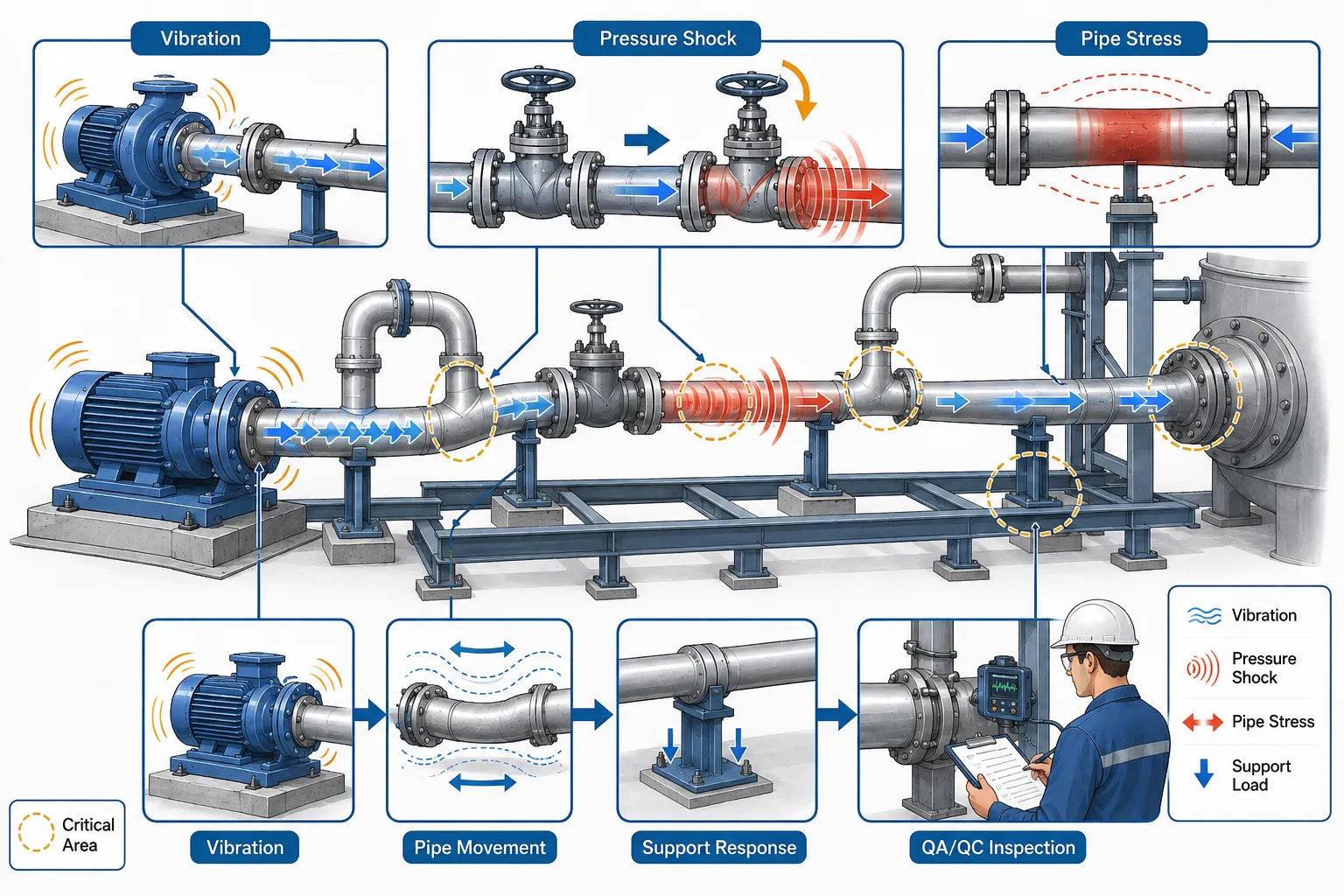
A dynamic load is a force or pressure that changes with time. Unlike a constant static load, a dynamic load may vary in magnitude, direction, frequency, or duration. This variation can cause a piping system to move, vibrate, deform, or experience repeated stress cycles.
Dynamic loads may originate from the fluid inside the piping system, connected equipment, changes in operating conditions, or external environmental and mechanical influences.
Common sources include:
Pump operation
Compressor operation
Turbine operation
Reciprocating machinery
Rapid valve opening or closing
Sudden pump start-up or shutdown
Flow instability
Pressure pulsation
Water hammer
Steam hammer
Two-phase flow
Relief valve operation
Emergency shutdown events
Pressure surges
Mechanical resonance
Pipe-support interaction
External vibration
Seismic or environmental movement where applicable
The QA/QC professional needs to understand that dynamic loads can produce repeated stress cycles even when the average pressure in the system remains within the normal design range.
Definition of Structural Response
Structural response refers to the way a piping network, support structure, or mechanical component reacts when exposed to an applied force, pressure, vibration, thermal movement, or other loading condition.
The response may involve:
Stress
Strain
Displacement
Deflection
Rotation
Vibration
Acceleration
Deformation
Fatigue
Localised loading
Support movement
Connection movement
A structural response is not automatically a failure. The QA/QC objective is to determine whether the response remains within the specified design and acceptance requirements.
Piping Network Components Affected by Dynamic Loads
A piping network consists of interconnected components, and dynamic loads can be transmitted throughout the system.
Important components include:
Straight pipe sections
Elbows
Tees
Reducers
Flanges
Valves
Expansion joints
Flexible connections
Branch connections
Instrument connections
Welded joints
Supports
Guides
Anchors
Hangers
Pipe racks
Equipment nozzles
A problem originating at one location may therefore affect another component. For example, vibration generated by a pump may travel through connected piping and produce excessive movement at a support or equipment nozzle.
Types of Dynamic Operational Loads
Pressure Pulsation
Pressure pulsation occurs when fluid pressure repeatedly increases and decreases during operation. It is commonly associated with reciprocating pumps, compressors, and other equipment that generates periodic flow variations.
Repeated pressure fluctuations can result in:
Cyclic stress
Pipe vibration
Fatigue damage
Connection loosening
Seal deterioration
Instrument instability
Support movement
Noise
Increased maintenance requirements
QA/QC personnel should recognise pressure pulsation as a potential fatigue-related concern, particularly where the system contains small-bore connections, branch pipes, welded attachments, or other stress-sensitive features.
Fluid Pressure Shocks
A fluid pressure shock is a rapid change in fluid pressure caused by an abrupt change in flow velocity. One of the best-known examples is water hammer.
Pressure shocks can generate transient forces that travel through a piping network. If significant, these forces may produce sudden pipe movement, support loading, vibration, noise, or damage to components.
Water Hammer
Water hammer can occur when a flowing liquid is stopped or redirected rapidly, such as when a valve closes suddenly or a pump trips unexpectedly.
The sudden change in flow conditions can produce a pressure wave that travels through the piping system.
Potential consequences include:
Sudden pipe movement
High transient pressure
Support overload
Valve damage
Flange leakage
Joint displacement
Pipe deformation
Fatigue damage
Equipment nozzle loading
The severity depends on factors such as fluid velocity, pipe geometry, fluid properties, system length, valve characteristics, and the speed of the flow change.
Steam Hammer
Steam systems can experience severe dynamic effects when condensate accumulates and is rapidly accelerated by steam flow. This can produce impact forces and vibration.
Potential warning signs include:
Loud banging
Sudden pipe movement
Excessive vibration
Support movement
Insulation damage
Repeated leakage
Component failure
QA/QC controls should therefore consider appropriate drainage, pipe slope, support arrangement, operating procedures, and system design requirements.
Vibration in Piping Systems
Vibration is repeated oscillatory movement caused by dynamic forces. It can occur at low or high frequencies and may range from minor movement to severe oscillation.
Mechanical vibration may be transmitted from rotating or reciprocating equipment into connected piping.
Common sources include:
Pumps
Compressors
Fans
Turbines
Motors
Reciprocating machinery
Flow-induced turbulence
Pressure pulsation
Cavitation
Two-phase flow
Poorly supported piping
Persistent vibration is a significant QA/QC concern because repeated movement can contribute to fatigue and progressive deterioration.
Relationship Between Vibration and Fatigue
Fatigue is the progressive damage caused by repeated stress cycles. A piping component may withstand a single load that is below its ultimate strength but still experience fatigue if that load is repeated thousands or millions of times.
This is especially important for:
Welded joints
Branch connections
Small-bore connections
Pipe supports
Instrument connections
Nozzles
Attachment points
Geometric discontinuities
The QA/QC professional should therefore consider not only the maximum stress but also the frequency and number of stress cycles.
Piping Supports and Their Structural Function
Pipe supports are essential for maintaining the position, alignment, stability, and controlled movement of piping systems.
Supports may perform several functions:
Carry the weight of piping and fluid
Control vertical movement
Restrict unwanted lateral movement
Control axial movement
Guide thermal expansion
Resist dynamic loads
Protect connected equipment
Maintain required pipe slope
Prevent excessive vibration
A support that is incorrectly installed, damaged, loose, incorrectly located, or inadequately designed can significantly alter the dynamic behaviour of the piping system.
Types of Piping Supports
Common support arrangements include:
Rest Supports
These provide vertical support while allowing controlled movement in other directions where appropriate.
Hangers
Hangers support piping from an overhead structure and may accommodate controlled movement.
Guides
Guides restrict lateral movement while allowing specified axial movement.
Anchors
Anchors restrict movement and transfer forces into the supporting structure.
Spring Supports
Spring supports can accommodate vertical movement resulting from thermal expansion or other operational conditions.
Restraints
Restraints are used to control specific movements and may be important where dynamic forces or pressure thrusts need to be managed.
The selection and installation of supports must correspond with the design intent and specified requirements.
Dynamic Response of Support Structures
A pipe does not respond independently from its support structure. Dynamic forces can transfer from the piping into pipe racks, steelwork, brackets, anchors, and building structures.
If the supporting structure is insufficiently rigid or improperly connected, excessive movement may occur.
Potential consequences include:
Support deformation
Anchor damage
Structural vibration
Bolt loosening
Weld cracking
Bracket failure
Excessive pipe movement
Misalignment
Increased equipment nozzle loading
QA/QC inspections should therefore consider the complete load path from the pipe through the support to the supporting structure.
Key Concepts in Dynamic Piping Assessment
Several concepts are particularly important when evaluating dynamic response.
Natural Frequency
Every mechanical structure has natural frequencies at which it tends to vibrate when disturbed. If an operating excitation frequency is close to a natural frequency, resonance may occur.
Resonance
Resonance occurs when periodic excitation closely matches a natural frequency of the system. The resulting vibration amplitude can become significantly greater than under normal excitation.
Potential effects include:
Excessive pipe movement
Fatigue
Support damage
Connection failure
Noise
Equipment damage
Damping
Damping reduces vibration energy. Different materials, supports, restraints, and connections can provide different levels of damping.
Stiffness
Stiffness describes the resistance of a structure to deformation. Changing support spacing or restraint arrangements can change the stiffness and dynamic behaviour of a piping network.
Frequency
Frequency describes how often a cyclic load or vibration occurs over a given period. Frequency is important when evaluating the possibility of resonance and fatigue.
QA/QC Evaluation Process for Dynamic Piping Response
A systematic evaluation process helps ensure that dynamic effects are properly considered.
Step 1: Review Design and Technical Documentation
The first stage is to understand the intended design and operating conditions.
Relevant documentation may include:
Piping drawings
Isometric drawings
Piping and Instrumentation Diagrams
Line lists
Equipment data sheets
Support drawings
Design specifications
Material specifications
Operating conditions
Pressure and temperature information
Inspection and Test Plans
Applicable project requirements
Step 2: Identify Potential Dynamic Loads
The next stage is to identify where dynamic loads may occur.
Consider:
Pumps
Compressors
Rapid valve operation
Pressure relief events
Emergency shutdown
Flow changes
Two-phase flow
Pressure pulsation
Water hammer
Steam hammer
External vibration
Step 3: Identify Critical Locations
Not every section of piping has the same risk level. Particular attention should be given to locations where stress concentration, vibration, or movement could be significant.
Potentially critical areas include:
Branch connections
Elbows
Tees
Welded attachments
Small-bore connections
Equipment nozzles
Anchors
Supports
Long unsupported spans
Flexible connections
Changes in pipe direction
Step 4: Inspect Physical Conditions
The actual installation should be compared with approved drawings and specifications.
Inspect for:
Incorrect support locations
Missing supports
Loose supports
Damaged supports
Incorrect restraints
Unintended contact
Excessive pipe movement
Visible vibration
Misalignment
Damaged welds
Loose bolts
Distorted brackets
Signs of rubbing
Leakage
Step 5: Assess Operational Behaviour
Where appropriate and authorised, operational observations may be used to identify abnormal behaviour.
Observe:
Vibration
Noise
Pipe movement
Support movement
Valve response
Pressure fluctuations
Equipment interaction
Leakage
Repeated failure patterns
Step 6: Record and Evaluate Findings
Inspection findings should be documented accurately.
Records may include:
Inspection reports
Vibration readings
Photographs
Measurements
Pressure records
Support inspection records
Non-conformance reports
Corrective action records
Step 7: Determine Corrective Action
If the response exceeds specified requirements or indicates an unacceptable risk, appropriate corrective action should be initiated.
Corrective measures may include:
Installing or modifying supports
Improving restraint
Repairing damaged components
Replacing defective parts
Improving alignment
Addressing pressure pulsation
Modifying operating procedures
Reviewing valve operation
Investigating equipment vibration
Conducting further engineering assessment
Table: Dynamic Loads, Structural Response and QA/QC Controls
| Dynamic Condition | Structural Response | Potential Consequence | QA/QC Control |
|---|---|---|---|
| Pump vibration | Pipe oscillation and support movement | Fatigue and connection damage | Vibration inspection and support verification |
| Pressure pulsation | Cyclic stress | Fatigue cracking | Review operating data and inspect critical joints |
| Water hammer | Sudden pressure and force | Support overload or leakage | Verify system design and valve operation |
| Steam hammer | Impact and vibration | Pipe/support damage | Inspect drainage and support arrangements |
| Rapid valve closure | Pressure transient | Pipe displacement and component loading | Review valve operation and transient controls |
| Long unsupported span | Excessive deflection | Fatigue and misalignment | Verify support spacing |
| Resonance | High vibration amplitude | Accelerated fatigue | Dynamic assessment and vibration monitoring |
| Thermal movement | Expansion and displacement | Support or nozzle loading | Verify guides, anchors and expansion provisions |
| Two-phase flow | Flow-induced vibration | Fatigue and erosion | Assess flow conditions and vulnerable locations |
| Equipment excitation | Transmitted vibration | Joint and support deterioration | Inspect equipment connections and restraints |
Practical Example: Pump-Connected Piping
Consider a centrifugal pump connected to a process piping system. During operation, vibration is transferred from the pump into the connected pipework.
If the piping is adequately supported and aligned, the vibration may remain within acceptable limits. However, if a support is missing or incorrectly positioned, the piping may experience excessive movement.
A QA/QC professional may identify:
Excessive vibration at a pipe section
Movement near the pump nozzle
Loose support hardware
Damage to an attachment
Repeated flange leakage
The appropriate response would not simply be to tighten the flange. The underlying dynamic cause should be investigated.
Possible corrective actions may involve:
Verifying support arrangement
Checking alignment
Reviewing equipment vibration
Inspecting connected joints
Assessing support stiffness
Reviewing operating conditions
Recording the findings
Implementing corrective action
Practical Example: Water Hammer in a Liquid Piping System
Imagine a long liquid pipeline where a valve is closed rapidly. The sudden reduction in flow can create a pressure wave that travels through the piping system.
The resulting transient may cause:
Sudden movement
Noise
Support loading
Pressure fluctuations
Leakage
Damage to valves or joints
From a QA/QC perspective, the event should trigger consideration of the system’s design and operating controls rather than being treated solely as an isolated maintenance issue.
Relevant checks may include:
Valve closing characteristics
Support condition
Pipe restraint
Joint integrity
Pressure records
Previous incidents
Inspection findings
Practical Example: Small-Bore Connection Vibration
Small-bore connections can be particularly vulnerable to vibration because their geometry and connection arrangement may produce localised stress.
Repeated vibration can result in:
Fatigue cracking
Leakage
Weld deterioration
Instrument damage
Connection failure
QA/QC personnel should therefore avoid focusing exclusively on major pipe sections. Small-bore connections, branch connections, and instrument take-offs may require careful inspection where vibration is present.
Key Benefits of Evaluating Dynamic Structural Response
A structured evaluation provides important benefits to mechanical QA/QC management.
Improved Mechanical Integrity
Understanding dynamic behaviour helps identify conditions that could compromise piping integrity.
Reduced Fatigue Failure
Recognising repeated vibration and cyclic loading can support early intervention before fatigue damage becomes critical.
Improved Support Reliability
Inspection of supports helps ensure that dynamic forces are transferred safely into the supporting structure.
Reduced Leakage
Controlling vibration and pressure shocks can reduce deterioration of joints, seals, flanges, and connections.
Improved Equipment Protection
Appropriate piping support and restraint can reduce excessive loads transferred to connected equipment.
Better Inspection Planning
Dynamic risk information can help identify critical locations for targeted inspection.
Reduced Unplanned Downtime
Preventive control of dynamic problems can reduce unexpected equipment and piping failures.
Improved Quality Documentation
Recording dynamic observations, inspection findings, corrective actions, and verification activities strengthens the overall quality record.
QA/QC Documentation Requirements
Accurate documentation is fundamental when evaluating dynamic response.
Relevant records may include:
Approved piping drawings
Isometric drawings
Support drawings
Inspection and Test Plans
Pressure-test records
Vibration monitoring records
Equipment inspection reports
Support inspection records
Weld inspection records
Non-Conformance Reports
Corrective Action Reports
Photographic evidence
Engineering assessment reports
Final inspection records
Documentation should clearly identify the component, location, observed condition, inspection date, findings, required action, responsible party, and verification of completion where applicable.
Common QA/QC Issues Associated With Dynamic Loads
Learners should recognise several recurring quality issues.
Incorrect Support Installation
A support may be installed differently from the approved design, changing the intended load distribution.
Missing Supports
Missing supports can increase unsupported span length and allow excessive movement.
Loose Connections
Loose bolts, clamps, brackets, or restraints may allow movement that was not intended.
Uncontrolled Contact
Pipework may contact nearby structures, creating unexpected forces or vibration transmission.
Poor Alignment
Misalignment can introduce additional forces and stresses into piping and equipment connections.
Inadequate Inspection
If dynamic conditions are not considered during inspection planning, early signs of fatigue or support deterioration may be missed.
Failure to Investigate Repeated Leakage
Repeated leakage may indicate an underlying vibration, pressure, support, or alignment problem rather than simply a defective gasket.
Role of the Learner in QA/QC Practice
Learners should develop the ability to approach dynamic piping conditions systematically rather than making assumptions based solely on visual appearance.
They should be able to:
Recognise common sources of dynamic loading.
Understand the difference between static and dynamic loading.
Identify potential vibration sources.
Understand pressure shock mechanisms.
Recognise the importance of piping supports.
Identify potentially vulnerable components.
Review relevant quality documentation.
Compare physical installation against approved requirements.
Record inspection findings accurately.
Recognise when further technical assessment may be necessary.
Support corrective and preventive actions.
Understand the importance of engineering approval for design changes.
A QA/QC professional should also recognise the limits of their role. Where a dynamic problem requires detailed stress analysis, transient analysis, vibration modelling, or design modification, the issue should be referred to appropriately qualified engineering personnel rather than resolved through an unauthorised field modification.
Summary
Piping networks and their support structures can experience significant dynamic forces during normal and abnormal operation. Pumps, compressors, pressure pulsation, rapid valve operation, water hammer, steam hammer, flow instability, and other dynamic conditions can generate vibration, transient pressure, cyclic stress, displacement, and support loading.
The structural response of the system depends on factors such as pipe geometry, material properties, support configuration, restraint arrangement, operating conditions, excitation frequency, stiffness, damping, and component condition. Excessive dynamic response can contribute to fatigue, cracking, leakage, support failure, connection deterioration, equipment nozzle loading, and premature mechanical failure.
For QA/QC professionals, effective evaluation involves identifying dynamic load sources, reviewing design and operating information, inspecting supports and connections, recognising signs of abnormal vibration or movement, documenting findings, and ensuring appropriate corrective actions are implemented.
The central principle is that piping integrity depends on the behaviour of the complete system, not simply the strength of individual pipe sections. Pipes, fittings, valves, supports, restraints, connected equipment, and supporting structures must work together within their intended design conditions.
By developing a systematic understanding of dynamic loads and structural response, Learners can contribute more effectively to quality planning, inspection, defect prevention, mechanical integrity, reliability, and safe operation of industrial piping systems.
3.Use Load Testing Data to Adjust Quality Inspection Boundaries, Ensuring High-Stress Areas Receive Appropriate Inspection Attention
Load testing is an important source of engineering information for understanding how mechanical systems, components, piping networks, supports, and structural assemblies respond when subjected to defined loading conditions. In QA/QC, the value of load testing data extends beyond simply confirming whether a component can withstand a specified load. Properly analysed test data can help identify areas experiencing comparatively high stresses, excessive displacement, abnormal deformation, unexpected vibration, or other responses that may require increased inspection attention.
A quality inspection boundary defines the physical and technical extent within which inspection activities are performed. In a conventional inspection programme, inspection boundaries may be established according to drawings, equipment limits, component classifications, design specifications, risk categories, or predefined inspection procedures. However, actual load testing results may demonstrate that some areas experience greater stress or movement than originally anticipated. In such circumstances, QA/QC planning should use the available evidence to refine inspection priorities.
The fundamental principle is that inspection resources should be directed towards locations where the likelihood or consequence of quality deterioration is greatest. Load testing data provides objective evidence that can support this risk-based approach. High-stress areas may require closer visual inspection, dimensional checks, non-destructive testing, vibration monitoring, coating assessment, weld examination, or more frequent follow-up inspections, depending on the nature and criticality of the component.
This approach does not mean that low-stress areas can automatically be ignored. Rather, it means that inspection intensity, frequency, methods, and boundaries can be proportionately adjusted based on technical evidence, approved procedures, applicable requirements, and engineering judgement.
Understanding Load Testing Data
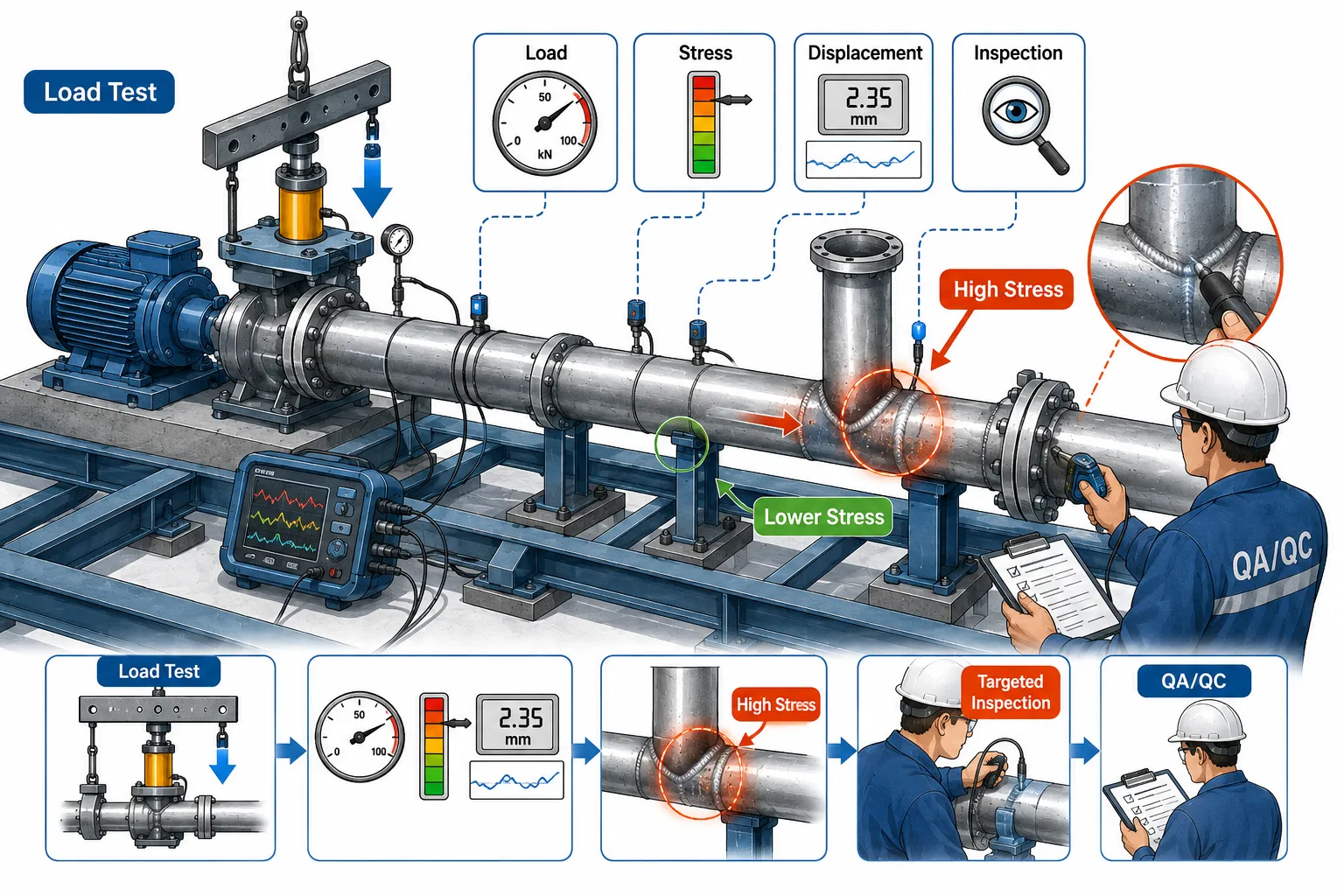
Load testing involves applying a defined load or operating condition to a mechanical component, system, structure, or assembly and measuring its response. The purpose and method of testing depend on the equipment and the applicable technical requirements.
Load testing may generate information about:
Applied load
Stress
Strain
Deflection
Displacement
Deformation
Pressure
Temperature
Vibration
Acceleration
Load distribution
Support reaction
Component movement
Structural response
Permanent deformation
The data can be obtained through appropriately selected measurement equipment and testing procedures. The resulting information provides evidence about how the system behaves under specified conditions.
Definition of Load Testing Data
Load testing data can be defined as the measured and recorded information obtained while a component, structure, piping system, support arrangement, or mechanical assembly is subjected to a specified load or operational condition.
The data may be used to:
Verify expected structural behaviour
Identify abnormal response
Compare actual and expected performance
Identify high-stress or high-deformation regions
Support engineering evaluation
Establish inspection priorities
Identify potential quality concerns
Support corrective action
Improve future inspection planning
Why Load Testing Matters in QA/QC
QA/QC activities should ideally be based on objective evidence rather than assumptions. Load testing provides a practical means of obtaining evidence about actual system behaviour.
A component may appear satisfactory during a visual inspection but exhibit excessive deformation under load. Similarly, a pipe support may appear correctly installed but experience unexpected movement during operation.
Load testing can therefore reveal conditions that may not be visible during static inspection.
Important QA/QC Questions
When reviewing load testing data, a QA/QC professional should consider:
What load was applied?
Was the test performed according to an approved procedure?
What was the expected response?
What was the actual response?
Where was the highest measured stress or deformation?
Were any unexpected movements observed?
Did the component return to its original condition after unloading?
Were acceptance criteria established?
Were any measurements outside specified limits?
Does the result require additional inspection?
Has the result been reviewed by the appropriate technical personnel?
Key Concept: Inspection Boundaries
An inspection boundary establishes the area, component, system, or set of features covered by a particular inspection activity.
For example, an inspection boundary may include:
A complete piping section
A weld area
A support assembly
A pressure vessel connection
A structural bracket
A flange connection
A mechanical component
A defined length of pipe
A specific equipment interface
Inspection boundaries should be sufficiently broad to identify relevant defects but should also be logically defined so that inspection resources are used effectively.
Fixed Versus Risk-Based Inspection Boundaries
Traditional inspection boundaries may be fixed according to predetermined requirements. A risk-based approach allows the inspection boundary or intensity to be refined using evidence such as load testing results, operating history, previous defects, failure mechanisms, and component criticality.
A high-stress region may therefore require a more detailed inspection boundary than an area demonstrating consistently low and stable stress.
Relationship Between Stress and Inspection Priority
Stress is a measure of the internal forces acting within a material as a result of an applied load. High stress does not automatically mean that failure will occur. However, areas experiencing elevated or fluctuating stress may have greater susceptibility to certain forms of damage, particularly when combined with fatigue, corrosion, poor geometry, defects, or repeated loading.
High-stress locations may include:
Welded joints
Pipe bends
Branch connections
Nozzle connections
Supports
Anchors
Flanges
Changes in cross-section
Structural discontinuities
Areas with stress concentrations
Equipment interfaces
Load testing data can help identify which areas deserve closer consideration during QA/QC inspection.
Stress Concentration and Inspection Boundaries
Stress concentration occurs when the local stress in a component is significantly greater than the average stress due to changes in geometry, discontinuities, holes, notches, weld profiles, sharp transitions, or other features.
Examples include:
Weld toes
Weld roots
Sharp geometric transitions
Branch connections
Bolt holes
Nozzle intersections
Pipe supports
Abrupt changes in section thickness
These locations can become important inspection points because defects or imperfections may have a greater effect when they occur in an already highly stressed region.
Using Load Testing Data to Refine Inspection Boundaries
The process should be systematic and evidence-based. Load testing data should not be used to arbitrarily change inspection requirements. Any adjustment should remain consistent with approved specifications, applicable standards, contractual requirements, inspection procedures, and engineering authority.
Step 1: Establish the Original Inspection Boundary
Before analysing the test results, identify the existing inspection scope.
Review:
Approved inspection plans
Inspection and Test Plans
Engineering drawings
Component classifications
Quality specifications
Previous inspection records
Applicable acceptance criteria
Risk assessments
The original boundary provides the baseline against which any proposed adjustment can be considered.
Step 2: Review the Load Testing Method
The reliability of the conclusions depends on the quality of the test itself.
Verify:
Test procedure approval
Test equipment suitability
Instrument calibration
Test load
Test duration
Loading sequence
Environmental conditions
Measurement locations
Data recording method
Personnel competency
Test acceptance criteria
Poor-quality test data should not be used as the sole basis for changing an inspection strategy.
Step 3: Analyse the Test Results
The measured results should be compared with the expected or specified response.
Review:
Maximum stress
Maximum displacement
Deflection
Strain
Permanent deformation
Vibration
Load distribution
Response under increasing load
Response during unloading
Differences between locations
Particular attention should be given to locations showing unusual or elevated response.
Step 4: Map High-Stress Locations
The test results should be associated with physical locations on drawings or inspection plans.
For example, if load testing identifies higher strain near a branch connection, the inspection boundary may need to ensure that the branch connection, adjacent welds, surrounding pipe section, and associated support arrangement are adequately examined.
Step 5: Evaluate Potential Failure Mechanisms
High stress alone does not determine the inspection method. QA/QC personnel should consider what type of deterioration could occur.
Potential mechanisms include:
Fatigue
Cracking
Plastic deformation
Weld deterioration
Corrosion-assisted cracking
Bolt loosening
Support damage
Localised deformation
Leakage
Coating breakdown
The likely failure mechanism helps determine the appropriate inspection technique.
Step 6: Adjust Inspection Intensity
Where justified, inspection intensity may be increased in high-risk areas.
Possible measures include:
More detailed visual inspection
Increased inspection frequency
Additional dimensional checks
Targeted NDT
Weld examination
Vibration monitoring
Surface inspection
Thickness measurement
Support inspection
Repeat load testing
Additional engineering assessment
Step 7: Maintain the Required Inspection Coverage
High-priority areas should receive increased attention without automatically removing other areas from mandatory inspection requirements.
This distinction is essential. A risk-based enhancement should supplement or refine approved requirements unless an authorised engineering or quality authority formally approves a change.
Table: Using Load Testing Data to Prioritise Inspection
| Load Testing Finding | Possible Significance | Inspection Response | QA/QC Objective |
|---|---|---|---|
| Elevated stress at weld | Potential fatigue or weld-related concern | Detailed weld inspection and appropriate NDT | Identify defects before progression |
| Excessive pipe displacement | Possible inadequate support or restraint | Inspect supports, guides and anchors | Confirm system stability |
| Permanent deformation | Possible yielding or overload | Engineering assessment and dimensional inspection | Establish component integrity |
| High vibration | Potential cyclic fatigue | Vibration monitoring and targeted inspection | Identify repeated-load damage |
| Localised strain concentration | Stress concentration | Inspect geometry, welds and connections | Identify vulnerable locations |
| Abnormal support movement | Load-transfer concern | Inspect support and structural connection | Verify load path |
| High stress near nozzle | Potential equipment interface loading | Inspect nozzle and connected piping | Protect equipment and piping integrity |
| Repeated abnormal test response | Possible unresolved design or operational issue | Expanded inspection and technical review | Identify root cause |
| Stable low response | Lower relative risk | Maintain planned inspection controls | Use resources proportionately |
| Unexpected response during unloading | Possible permanent deformation | Dimensional inspection and engineering review | Verify recovery and integrity |
Determining High-Stress Areas
High-stress areas should be identified using reliable technical evidence. Depending on the system, this may involve direct strain measurements, stress analysis, displacement measurements, engineering calculations, finite element analysis, or other approved assessment techniques.
Common High-Stress Locations in Mechanical Systems
High-stress regions may include:
Welded connections
Pipe bends
Branch connections
Nozzle intersections
Anchored sections
Pipe-support connections
Structural brackets
Flanged connections
Changes in pipe diameter
Changes in wall thickness
Equipment interfaces
Areas subjected to repeated loading
These areas should receive particular consideration because a small defect in a highly stressed region may have greater significance than the same defect in a low-stress region.
Load Testing and Piping Networks
Piping systems provide an important example of how load testing data can influence inspection boundaries.
Piping may experience loads from:
Internal pressure
Fluid weight
Thermal expansion
Equipment movement
Pressure transients
Vibration
Support reactions
External forces
A load test may demonstrate that a particular support or branch connection experiences greater movement than expected. This information can be used to refine the inspection scope around that location.
Example of an Adjusted Piping Inspection Boundary
Suppose a piping system contains a branch connection approximately midway along a pipeline. Load testing identifies elevated strain around the branch connection under an operational load.
The original inspection boundary may have included only the main pipe weld. However, the test evidence indicates that the surrounding area is structurally significant.
A more appropriate inspection boundary could include:
Branch connection weld
Adjacent pipe wall
Nearby support
Supporting bracket
Connected small-bore piping
Local coating condition
Evidence of deformation
Nearby bolted connections
This provides a more complete assessment of the area influenced by the elevated load response.
Load Testing and Support Structures
Pipe supports transfer forces from piping into structural systems. Load testing can reveal whether the actual load distribution is consistent with the design assumptions.
Potential findings may include:
Unexpected support loading
Uneven load distribution
Excessive bracket deformation
Movement at anchors
Support settlement
Bolt movement
Welded support distress
Contact between pipe and structural members
Where such conditions are identified, inspection boundaries should consider both the pipe and its support structure.
Using Test Data to Determine Inspection Frequency
Load testing data can also inform inspection frequency where this is permitted by the applicable quality management system.
Areas demonstrating:
High stress
Significant cyclic loading
Elevated vibration
Previous defects
Rapid deterioration
Unusual deformation
may justify more frequent monitoring or inspection.
Areas demonstrating:
Stable behaviour
Low relative stress
No evidence of deterioration
Good historical performance
may remain under standard inspection controls.
The important principle is that inspection frequency should be determined through documented risk assessment rather than subjective assumptions.
High-Stress Areas and Non-Destructive Testing
Where high-stress regions contain welds or other susceptible features, appropriate NDT may provide additional assurance.
Depending on the material, component, defect mechanism, and approved inspection requirements, methods may include:
Visual testing
Surface examination
Ultrasonic examination
Radiographic examination
Magnetic particle examination
Other appropriately specified NDT methods
The selection of an inspection technique should be based on the expected defect type, material, component geometry, accessibility, applicable requirements, and competent technical judgement.
QA/QC personnel should not automatically assume that one NDT method is appropriate for every high-stress area.
Load Testing Data and Quality Risk Assessment
Load testing results can contribute to a broader quality risk assessment.
A practical risk evaluation may consider:
Risk = Likelihood of degradation or failure × Consequence of failure
The assessment may also consider:
Component criticality
Operating conditions
Load magnitude
Load frequency
Stress concentration
Material susceptibility
Existing defects
Corrosion exposure
Historical failure data
Accessibility
Detectability of defects
A high-stress component in a critical service may therefore warrant significantly greater inspection attention than a similarly stressed component in a non-critical application.
Practical Example: Structural Support Under Repeated Loading
Consider a steel support structure carrying a process piping network. During load testing, measurements indicate that one support experiences significantly greater deflection than neighbouring supports.
The finding should prompt a structured QA/QC review.
Initial Observations
The QA/QC team may identify:
Higher-than-expected deflection
Localised movement
Visible coating damage
Slight deformation around a connection
Repeated vibration during operation
Expanded Inspection Boundary
Instead of inspecting only the support bracket, the assessment may include:
Support bracket
Welded connection
Anchor bolts
Supporting steelwork
Adjacent pipe section
Pipe-to-support interface
Nearby pipe guides
Signs of fatigue or cracking
Possible Outcome
If inspection identifies a defect, the issue should be documented and managed through the applicable non-conformance and corrective action process. If no defect is identified, the location may still be classified as a higher-priority monitoring point because of its demonstrated load response.
Practical Example: High Stress at a Welded Branch Connection
A load test on a process piping system identifies elevated strain near a welded branch connection.
The QA/QC team should consider whether the elevated response could increase susceptibility to fatigue or other deterioration.
The inspection strategy may include:
Detailed visual inspection
Weld profile examination
Surface condition assessment
Appropriate NDT where specified
Examination of adjacent pipe
Support inspection
Review of previous inspection records
Review of operating vibration
Engineering assessment where required
This approach ensures that the inspection boundary reflects the actual structural behaviour demonstrated by the test.
Practical Example: Pressure Load Testing of a Mechanical Component
Consider a mechanical component subjected to a controlled pressure or load test. The component passes the basic acceptance criterion but shows a higher-than-expected local deformation near a connection.
A simple pass/fail interpretation may overlook valuable information. From a QA/QC perspective, the unusual response should be recorded and reviewed.
Potential actions could include:
Verification of measurement accuracy
Review of component design
Dimensional inspection
Inspection of the connection
Review of material documentation
Review of manufacturing records
Engineering assessment
Additional testing if justified
The purpose is to distinguish acceptable behaviour from an early indication of a potential quality issue.
Benefits of Using Load Testing Data to Refine Inspection
Evidence-Based Inspection
Testing provides measurable evidence that can improve inspection planning.
Early Identification of Vulnerable Locations
High-stress or high-displacement areas can be identified before serious deterioration develops.
Better Resource Allocation
Inspection personnel and specialist techniques can be concentrated where they provide the greatest quality benefit.
Improved Defect Detection
Targeted inspection can increase the likelihood of detecting defects in critical areas.
Reduced Failure Risk
Early identification of high-risk conditions supports preventive action.
Improved Mechanical Reliability
Monitoring high-stress areas contributes to maintaining system integrity over its intended service life.
Better Maintenance Planning
Test results can support decisions regarding inspection intervals, monitoring requirements, and preventive maintenance.
Stronger Quality Assurance
Documented evidence linking test results to inspection decisions demonstrates a structured quality management approach.
Important Limitations When Using Load Testing Data
Load testing data is valuable, but it must be interpreted correctly.
Test Conditions May Not Represent Every Operating Condition
A test may represent a particular load case but not every possible operational scenario.
Measurement Error Is Possible
Sensors and instruments have limitations. Calibration and measurement uncertainty should be considered.
High Stress Does Not Automatically Mean Failure
Stress should be evaluated against relevant design criteria, material behaviour, fatigue considerations, and engineering requirements.
Low Stress Does Not Guarantee No Risk
Other degradation mechanisms, such as corrosion, manufacturing defects, poor weld quality, or environmental exposure, may still be present.
Engineering Assessment May Be Required
Complex structural response should be evaluated by appropriately qualified engineering personnel where necessary.
Inspection Requirements Still Apply
Load testing should not be used as a reason to disregard mandatory inspection, testing, regulatory, contractual, or project requirements.
QA/QC Documentation for Load-Test-Based Inspection Decisions
Every adjustment to an inspection strategy should be supported by appropriate documentation.
Records may include:
Approved load test procedure
Test results
Calibration certificates
Load and displacement measurements
Stress or strain records
Drawings showing test locations
Inspection reports
Risk assessment
Engineering review
Inspection boundary revision
NDT reports
Non-conformance records
Corrective action records
Verification records
Final approval documentation
Good documentation creates traceability between the original test, the identified risk, the inspection response, and the final quality decision.
Process for Integrating Load Testing With QA/QC Inspection
A structured process can be summarised as follows:
Stage 1: Establish Requirements
Identify design requirements, applicable specifications, acceptance criteria, and existing inspection boundaries.
Stage 2: Conduct or Review Testing
Ensure that the load test is performed using an approved procedure and suitable calibrated equipment.
Stage 3: Capture Reliable Data
Record relevant stress, strain, displacement, pressure, vibration, and load information.
Stage 4: Identify Significant Responses
Determine where measured responses are comparatively high or unusual.
Stage 5: Assess Risk
Evaluate the significance of the response considering component criticality, failure mechanisms, operating conditions, and consequences.
Stage 6: Refine Inspection Boundaries
Where justified, expand or intensify inspection around identified high-risk locations.
Stage 7: Select Appropriate Inspection Methods
Choose inspection techniques based on the suspected degradation mechanism and technical requirements.
Stage 8: Record Findings
Document inspection results accurately and maintain traceability.
Stage 9: Implement Corrective Action
Where defects or unacceptable conditions are identified, implement appropriate corrective action through approved processes.
Stage 10: Verify and Review
Confirm that corrective actions are effective and review whether future inspection planning should be modified.
Key Learning Points
Learners should understand that load testing data can provide valuable evidence for improving QA/QC inspection planning.
The main principles are:
Load testing provides information about actual structural response.
High-stress locations deserve careful technical evaluation.
Inspection boundaries should be based on approved requirements and supported by evidence.
Stress concentrations can increase the significance of defects.
Repeated loading can contribute to fatigue.
High vibration may require targeted inspection.
Piping supports form part of the structural load path.
Load testing can identify unexpected deformation or movement.
Test data should be verified before being used for quality decisions.
Risk assessment helps determine appropriate inspection intensity.
High-priority inspection should supplement, not arbitrarily replace, mandatory requirements.
Engineering assessment should be obtained where the response is complex or outside established acceptance criteria.
Inspection findings and decisions must be documented and traceable.
Conclusion
Using load testing data to adjust quality inspection boundaries represents an evidence-based approach to mechanical QA/QC. Rather than treating every area of a mechanical system as having identical inspection needs, load-response information can help identify locations where stresses, strains, displacement, vibration, or deformation are comparatively significant.
High-stress regions such as welds, branch connections, pipe bends, supports, anchors, equipment interfaces, and structural connections may require particular attention because repeated or concentrated loading can increase susceptibility to fatigue, cracking, deformation, loosening, leakage, or other forms of deterioration.
A competent QA/QC approach begins with an established inspection boundary and then uses reliable load testing information to identify whether additional attention is warranted. The process involves reviewing test procedures, validating measurements, analysing the response, mapping significant locations, evaluating potential failure mechanisms, conducting risk assessment, selecting appropriate inspection methods, documenting findings, and implementing corrective action where necessary.
The objective is not simply to increase inspections everywhere. It is to direct appropriate inspection attention towards areas where objective evidence indicates greater structural or quality risk, while maintaining compliance with approved specifications, contractual requirements, applicable standards, and established quality procedures.
When properly integrated into the QA/QC system, load testing data can improve defect detection, strengthen risk-based inspection planning, support preventive maintenance, reduce unexpected failures, and improve the long-term reliability and integrity of mechanical systems.