
Lesson 4: Ensure long-term durability and performance of mechanical systems.
Long-term durability and reliable performance are essential requirements for mechanical systems operating in demanding industrial, manufacturing, construction, energy, and engineering environments. Mechanical components are continuously exposed to loads, vibration, temperature changes, pressure, friction, wear, corrosion, environmental conditions, and operational cycles that can gradually reduce their performance. Lesson 4: Ensure long-term durability and performance of mechanical systems focuses on the engineering and QA/QC principles required to maintain mechanical integrity throughout the service life of components, assemblies, machinery, rotating equipment, piping systems, valves, and other critical assets. It explores how material selection, component condition, maintenance practices, inspection data, operating controls, and reliability strategies work together to support dependable mechanical performance.
Achieving long-term mechanical reliability requires a proactive approach rather than relying solely on corrective maintenance after equipment failure. Engineering teams need to understand degradation mechanisms such as fatigue, wear, corrosion, creep, erosion, thermal deterioration, misalignment, lubrication failure, and repeated mechanical loading. Condition monitoring, planned inspection, preventive maintenance, historical performance analysis, reliability indicators, and structured QA/QC controls can provide early evidence of deterioration and support timely intervention. Effective durability management also requires appropriate operating limits, accurate maintenance records, controlled component replacement, verification of repairs, and systematic evaluation of recurring defects. These measures help organisations reduce unexpected breakdowns, control maintenance costs, protect production continuity, and maintain consistent mechanical quality.
A sustainable mechanical performance strategy ultimately connects design requirements with real operating conditions throughout the asset lifecycle. By analysing performance trends, evaluating component condition, reviewing maintenance effectiveness, controlling degradation mechanisms, and implementing continuous improvement measures, engineering professionals can extend useful service life while maintaining safety, reliability, quality, and operational efficiency. The principles covered in this lesson are relevant to mechanical QA/QC engineering, asset integrity management, reliability engineering, industrial maintenance, manufacturing quality assurance, rotating equipment management, piping and valve systems, and heavy mechanical projects. This data-driven and preventive approach supports durable mechanical systems that continue to perform predictably under their intended operating conditions.
1. Evaluate the Effectiveness of Surface Protection Methods in Preventing Rust and Corrosion
Corrosion is one of the most significant threats to the long-term durability, reliability and performance of mechanical systems. Metallic components used in industrial plants, fabrication facilities, heavy engineering projects, pipelines, storage systems, structural assemblies, rotating equipment and outdoor installations can gradually deteriorate when their surfaces interact with moisture, oxygen, salts, chemicals, pollutants or other aggressive environments. If corrosion is not adequately controlled, it can reduce material thickness, weaken load-bearing sections, damage moving interfaces, increase maintenance requirements, contaminate products and eventually contribute to mechanical failure. Effective surface protection is therefore an important element of mechanical QA/QC, asset integrity and long-term reliability management.
Industrial coatings, protective painting systems and cathodic protection are widely used to control corrosion, but their effectiveness depends on selecting the correct protection strategy for the material, environment, component geometry and expected service conditions. A coating that performs well in a dry indoor environment may deteriorate rapidly in a marine or chemical environment. Similarly, cathodic protection can be highly effective for appropriate metallic structures but is not a universal substitute for coatings or sound material selection. Professional evaluation therefore requires more than asking whether a protection system has been applied; it requires determining whether the protection system is technically suitable, correctly installed, adequately inspected and capable of maintaining its intended performance throughout the required service period.
Understanding Rust and Corrosion
Corrosion is the deterioration of a material, particularly a metal, through chemical or electrochemical interaction with its environment. For many common ferrous materials, corrosion produces iron oxides and hydroxides commonly described as rust. However, corrosion is not limited to visible red-brown rust. Different materials and environments can produce different forms of deterioration.
The fundamental corrosion process involves interaction between the metal and its environment. In many cases, moisture acts as an electrolyte while oxygen and other environmental constituents participate in electrochemical reactions. Surface contamination, salts, acidic conditions, temperature, differential aeration and contact with dissimilar metals can influence the rate and distribution of corrosion.
For mechanical QA/QC professionals, the important issue is that corrosion can progressively change the physical condition of a component. A component may initially retain its required dimensions, but progressive material loss can eventually reduce its ability to withstand mechanical loads.
Typical consequences include:
- Reduction in wall thickness.
- Surface pitting.
- Loss of dimensional accuracy.
- Reduction in effective cross-sectional area.
- Increased surface roughness.
- Seizure of moving components.
- Leakage through pressure boundaries.
- Reduced structural integrity.
- Increased maintenance requirements.
- Premature component replacement.
Key Concepts and Definitions
| Key concept | Definition | Mechanical QA/QC relevance |
|---|---|---|
| Corrosion | Deterioration of metal through interaction with its environment | Can reduce component integrity and service life |
| Rust | Corrosion products commonly formed on iron and steel | Visible indication of ferrous material deterioration |
| Surface protection | Method used to isolate or electrically protect metal from corrosive conditions | Helps extend component service life |
| Industrial coating | Protective coating system applied to a prepared surface | Creates a physical barrier against the environment |
| Paint system | Combination of coating layers designed for corrosion protection and performance | Provides barrier and environmental resistance |
| Cathodic protection | Electrochemical corrosion-control technique that makes the protected metal act as the cathode | Reduces corrosion of suitable metallic structures |
| Surface preparation | Cleaning and conditioning performed before coating | Critical to coating adhesion and durability |
| Adhesion | Ability of a coating to remain attached to its substrate | Important for long-term coating performance |
| Coating thickness | Thickness of the applied protective coating | Must be controlled according to the specified system |
| Holiday | Localised discontinuity or pinhole in a protective coating | Can expose the substrate to the environment |
| Coating failure | Loss of protective performance of the coating | Can permit corrosion initiation or progression |
| Sacrificial anode | Material intentionally consumed to provide cathodic protection | Supplies protective current to the structure |
| Impressed current | Cathodic protection using an external electrical power source | Provides controlled protective current |
| Corrosion allowance | Additional material thickness provided for expected corrosion loss | Provides additional service margin |
| Inspection interval | Planned period between condition assessments | Supports ongoing corrosion monitoring |
Why Surface Protection Is Important
The primary objective of surface protection is to reduce the interaction between the metallic substrate and the environment or to control the electrochemical conditions that cause corrosion.
Effective protection can:
- Reduce corrosion initiation.
- Slow corrosion progression.
- Protect structural dimensions.
- Extend component service life.
- Reduce maintenance frequency.
- Reduce unplanned replacement.
- Protect pressure boundaries.
- Improve equipment appearance where relevant.
- Reduce contamination risks.
- Support asset integrity.
- Maintain mechanical performance.
Surface protection should therefore be considered as part of the overall engineering strategy rather than as a cosmetic finishing activity.
Major Surface Protection Strategies
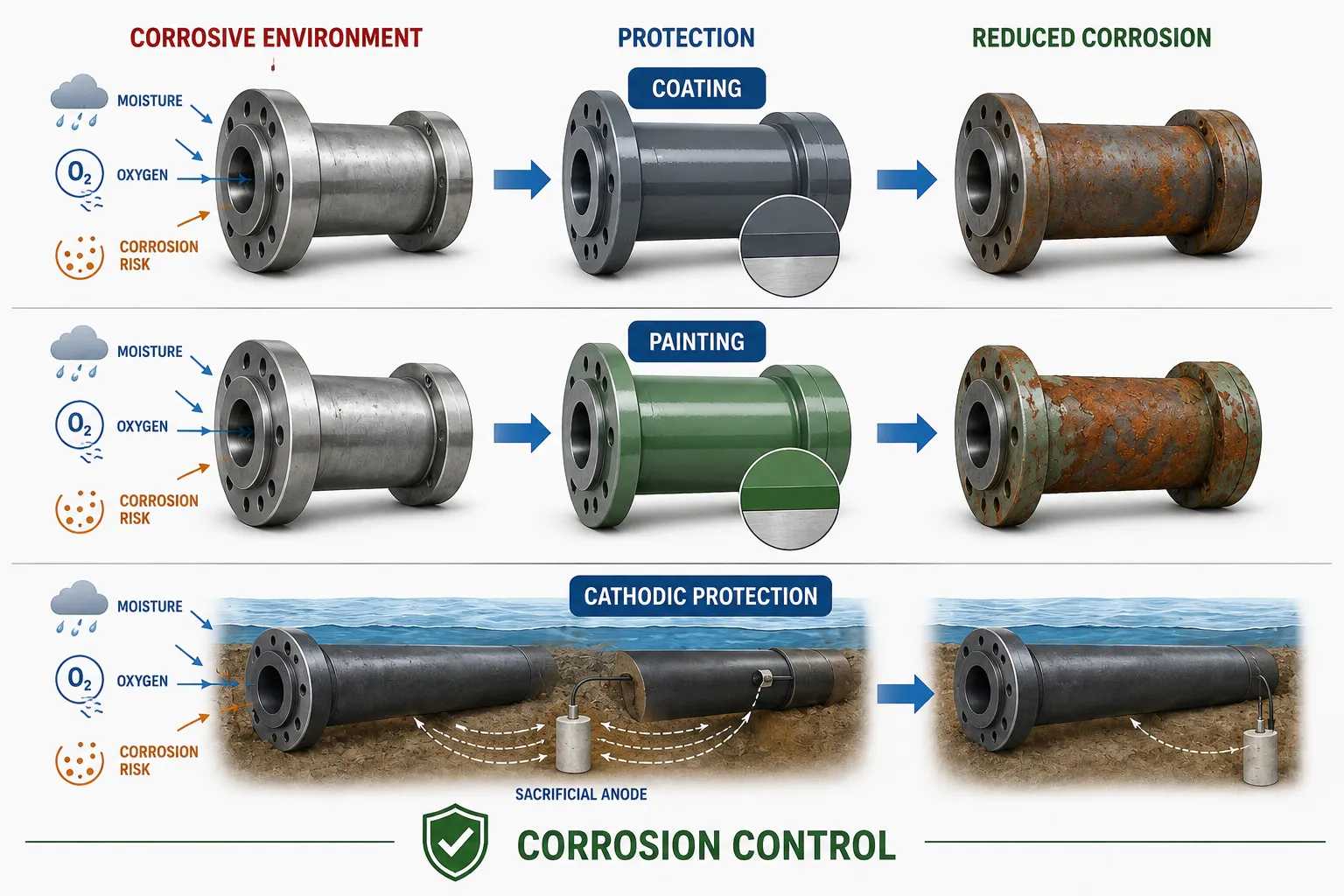
Three important approaches considered in this context are:
Industrial Coatings
Industrial coatings create a physical barrier between the metallic surface and corrosive environmental conditions.
Painting Systems
Industrial painting generally uses multiple coating layers selected for specific functions, such as adhesion, corrosion resistance and environmental durability.
Cathodic Protection
Cathodic protection changes the electrochemical behaviour of the protected metal so that corrosion of the protected structure is substantially reduced.
These methods can be used independently or in combination.
Industrial Coatings
Industrial coatings are engineered protective systems rather than simply decorative paint. A properly selected coating system can provide resistance against:
- Moisture.
- Atmospheric exposure.
- Salt contamination.
- Chemicals.
- Abrasion.
- Temperature.
- Ultraviolet exposure.
- Industrial pollutants.
The coating acts primarily as a barrier between the substrate and the environment.
The effectiveness of an industrial coating depends heavily on:
- Substrate condition.
- Surface preparation.
- Coating selection.
- Environmental conditions during application.
- Mixing and application quality.
- Coating thickness.
- Curing.
- Inspection.
- Service environment.
A high-quality coating material cannot compensate for poor surface preparation or inappropriate application.
Surface Preparation
Surface preparation is one of the most important factors affecting coating durability.
The substrate may contain:
- Rust.
- Mill scale.
- Oil.
- Grease.
- Dust.
- Salts.
- Moisture.
- Old coating.
- Welding residues.
- Abrasive contamination.
If these contaminants remain between the metal and coating, they can compromise adhesion and create pathways for corrosion.
A professional surface-preparation process may include:
- Initial visual inspection.
- Removal of oil and grease.
- Removal of loose corrosion.
- Mechanical cleaning where appropriate.
- Abrasive blasting where specified.
- Removal of dust.
- Surface-profile assessment where required.
- Verification of cleanliness.
- Environmental condition checks.
Importance of Surface Cleanliness
Coatings need a suitably prepared substrate to achieve reliable adhesion.
Contamination can cause:
- Poor coating adhesion.
- Blistering.
- Underfilm corrosion.
- Peeling.
- Premature delamination.
- Localised coating failure.
Therefore, QA/QC inspection should verify surface condition before coating application.
Coating System Design
A protective coating system may contain several layers, each with a specific function.
Primer
The primer generally provides adhesion to the prepared substrate and contributes to corrosion protection.
Intermediate Coat
An intermediate layer can provide additional barrier protection and contribute to the required coating thickness.
Topcoat
The topcoat provides environmental resistance and may protect the underlying layers from:
- UV exposure.
- Moisture.
- Chemicals.
- Abrasion.
- Weathering.
The exact coating system should be selected according to the specified service environment and engineering requirements.
Evaluating Coating Effectiveness
Coating effectiveness should be assessed using evidence rather than appearance alone.
Important evaluation criteria include:
- Surface preparation quality.
- Coating adhesion.
- Coating thickness.
- Surface coverage.
- Visual condition.
- Presence of defects.
- Environmental exposure.
- Curing condition.
- Resistance to the intended service environment.
- Long-term degradation behaviour.
A coating may appear visually satisfactory while still having inadequate thickness or hidden discontinuities.
Coating Thickness Control
Coating thickness is an important QA/QC parameter.
Insufficient thickness may reduce barrier protection, while excessive thickness can sometimes create its own problems depending on the coating system and application requirements.
Inspection should therefore verify:
- Specified coating system.
- Required thickness range.
- Measurement locations.
- Instrument suitability.
- Calibration or verification status.
- Recorded results.
Coating thickness measurements should be representative of the component rather than based on one convenient measurement point.
Coating Discontinuities
A protective coating can contain discontinuities that allow moisture or corrosive substances to reach the substrate.
Potential defects include:
- Pinholes.
- Holidays.
- Cracks.
- Blisters.
- Runs.
- Sags.
- Poor coverage.
- Delamination.
- Contamination.
- Mechanical damage.
These defects should be identified and assessed before the component enters service.
Cathodic Protection
Cathodic protection uses an electrochemical principle to reduce corrosion of a metallic structure.
The protected structure is made to behave as the cathode within the electrochemical system. This reduces the tendency of the protected metal to undergo anodic dissolution.
Two broad approaches are commonly used:
- Sacrificial-anode cathodic protection.
- Impressed-current cathodic protection.
Cathodic protection is commonly considered for suitable buried, submerged or continuously exposed metallic structures where electrochemical corrosion control is practical.
Sacrificial-Anode Cathodic Protection
A sacrificial-anode system uses a metal that is more readily oxidised than the protected structure.
The anode progressively consumes itself while providing the electrochemical protection required for the structure.
The system generally involves:
- Protected metallic structure.
- Sacrificial anode.
- Electrolyte.
- Electrical connection.
Potential advantages include:
- Simpler system configuration.
- No external power source for the protective current.
- Suitability for certain submerged or buried applications.
- Relatively straightforward operation.
However, the anodes are consumed and eventually require replacement.
Impressed-Current Cathodic Protection
An impressed-current system uses an external power source to provide protective current.
Typical elements include:
- Protected structure.
- Anode system.
- DC power source.
- Electrical connections.
- Monitoring equipment.
Potential advantages include:
- Ability to provide controlled protective current.
- Suitability for larger structures in appropriate applications.
- Adjustable protection according to system requirements.
However, the system requires appropriate electrical control, monitoring and maintenance.
Comparing Coatings and Cathodic Protection
| Protection method | Primary mechanism | Main strength | Important limitation | Typical QA/QC focus |
|---|---|---|---|---|
| Industrial coating | Physical/environmental barrier | Broad surface protection | Can deteriorate or develop defects | Surface preparation, thickness, adhesion and defects |
| Painting system | Multi-layer protective barrier | Flexible system selection | Performance depends heavily on application quality | Coating specification, application and inspection |
| Sacrificial anode | Electrochemical protection | Does not require external power | Anode consumption | Anode condition and system performance |
| Impressed current | Controlled electrochemical protection | Adjustable protection | Requires power and monitoring | Electrical output and protection performance |
| Coating + cathodic protection | Combined barrier and electrochemical control | Provides complementary protection | More complex management | Both coating and CP systems require monitoring |
Combining Coatings with Cathodic Protection
In many applications, coatings and cathodic protection can complement one another.
The coating reduces the area of exposed metal, while cathodic protection can help protect areas where the coating contains defects or becomes locally damaged.
The combination can provide:
- Reduced corrosion exposure.
- Lower cathodic-protection current demand where applicable.
- Additional protection at coating defects.
- Longer asset service potential.
- Improved corrosion-control reliability.
However, the two systems must be designed and monitored appropriately. Cathodic protection should not be regarded as justification for poor coating quality.
Practical Example: Industrial Storage Tank
Consider a steel storage tank exposed to an aggressive environment.
Potential corrosion-control measures may include:
- Appropriate material selection.
- Surface preparation.
- Multi-layer coating.
- Coating inspection.
- Periodic visual inspection.
- Thickness monitoring.
- Cathodic protection where technically appropriate.
The QA/QC process should verify that the protective system has been correctly installed before commissioning and that subsequent inspection confirms continuing performance.
Practical Example: Outdoor Steel Mechanical Structure
An outdoor steel mechanical structure is exposed to:
- Rain.
- Humidity.
- Atmospheric pollutants.
- Temperature changes.
- UV exposure.
A suitable coating system may provide the principal corrosion barrier.
Inspection should monitor:
- Peeling.
- Blistering.
- Cracking.
- Rust breakthrough.
- Mechanical damage.
- Coating deterioration.
Areas where the coating has been damaged should be repaired before corrosion becomes established.
Practical Example: Buried Steel Pipeline
A buried steel pipeline can be exposed to soil-related corrosion mechanisms.
A corrosion-control strategy may combine:
- Protective coating.
- Cathodic protection.
- Electrical isolation where appropriate.
- Monitoring.
- Periodic integrity assessment.
The coating provides the primary barrier, while cathodic protection can provide additional electrochemical protection where exposed metal exists.
Environmental Factors Affecting Coating Performance
The service environment has a major influence on coating durability.
Relevant factors include:
- Humidity.
- Temperature.
- Salt exposure.
- Chemical concentration.
- UV radiation.
- Abrasion.
- Mechanical impact.
- Immersion.
- Condensation.
- Pollution.
- Cyclic wetting and drying.
A coating should therefore be evaluated against the actual environment rather than a generic corrosion category.
Application Conditions
Coating application can be affected by environmental conditions.
Important considerations may include:
- Surface temperature.
- Ambient temperature.
- Humidity.
- Condensation risk.
- Cleanliness.
- Ventilation.
- Recoat interval.
- Curing conditions.
If the substrate is contaminated or conditions are unsuitable, coating performance can be significantly reduced.
Coating Failure Mechanisms
Common coating failures include:
Blistering
Localised loss of adhesion can create raised areas beneath the coating.
Peeling
The coating separates from the substrate or another coating layer.
Cracking
The coating develops visible fractures that may expose the substrate.
Delamination
A coating layer loses adhesion from the underlying surface or coating layer.
Rust breakthrough
Corrosion becomes visible through or around the coating.
Mechanical damage
Impact, abrasion or handling damages the protective barrier.
Each failure mechanism should be assessed to determine whether local repair or broader coating-system intervention is required.
Inspection of Protective Coatings
A QA/QC inspection programme may include:
- Substrate inspection.
- Surface cleanliness verification.
- Environmental-condition checks.
- Coating identification.
- Visual inspection.
- Thickness measurement.
- Adhesion assessment where specified.
- Holiday detection where appropriate.
- Defect mapping.
- Repair verification.
Inspection results should be documented and traceable to the relevant component or area.
Importance of Holiday Detection
A holiday is a discontinuity in a protective coating that exposes or potentially exposes the substrate.
Holiday detection can be particularly relevant where:
- The substrate is exposed to immersion.
- The coating system requires continuity.
- Small discontinuities could lead to significant corrosion.
The inspection method and test parameters should be appropriate for the coating system and component.
Evaluating Cathodic Protection Effectiveness
Cathodic protection should also be evaluated through measurable evidence.
Potential monitoring activities include:
- Protective potential measurements.
- Current monitoring.
- Anode condition assessment.
- Electrical continuity checks.
- Isolation verification where applicable.
- Reference electrode monitoring.
- System performance review.
The objective is to confirm that the protected structure receives the intended level of corrosion control without introducing adverse effects.
Corrosion Monitoring
Long-term corrosion protection requires ongoing monitoring.
Monitoring may involve:
- Visual inspections.
- Coating condition surveys.
- Thickness measurements.
- Corrosion-rate analysis.
- Cathodic-protection measurements.
- NDT.
- Inspection of known corrosion-prone locations.
A single successful coating inspection does not guarantee lifetime protection.
Establishing a Corrosion Management Strategy
A robust corrosion-management process can follow:
- Identify the material.
- Identify the environment.
- Identify likely corrosion mechanisms.
- Assess consequence of corrosion.
- Select protection method.
- Define application requirements.
- Inspect installation.
- Establish baseline condition.
- Monitor degradation.
- Repair defects.
- Review effectiveness.
- Update the corrosion-control strategy.
Risk-Based Selection of Protection
Not every component requires the same protection system.
Selection should consider:
- Component criticality.
- Failure consequences.
- Environmental severity.
- Expected service life.
- Accessibility.
- Maintenance requirements.
- Operating temperature.
- Chemical exposure.
- Pressure.
- Material.
- Cost of failure.
For example, a critical pressure-containing component may require significantly more rigorous corrosion-control and inspection measures than a non-critical decorative surface.
Evaluating Long-Term Durability
The effectiveness of a protection method should be evaluated over time.
Useful indicators include:
- Corrosion rate.
- Coating deterioration.
- Number of coating repairs.
- Thickness reduction.
- Frequency of corrosion findings.
- Cathodic-protection performance.
- Component replacement frequency.
A protection system that performs well initially but deteriorates rapidly may not provide satisfactory lifecycle performance.
Case Study: Coating Failure on a Mechanical Assembly
Background
A steel mechanical assembly is installed outdoors and protected using an industrial coating system.
After several years, inspectors identify:
- Localised coating peeling.
- Rust breakthrough.
- Surface cracking.
- Increased corrosion around joints.
Investigation
The QA/QC team reviews:
- Original surface-preparation records.
- Coating thickness results.
- Environmental exposure.
- Previous repairs.
- Locations of recurring defects.
The investigation identifies that corrosion is concentrated around difficult-to-coat interfaces and mechanically damaged areas.
Preventive Measures
The organisation develops a revised corrosion-control strategy involving:
- Improved surface preparation.
- Localised repair.
- Improved coating coverage around interfaces.
- More frequent inspections.
- Condition mapping.
- Review of environmental exposure.
Outcome
The revised approach provides better visibility of degradation and reduces the likelihood that local coating defects will remain undetected until significant corrosion develops.
Case Study: Combined Coating and Cathodic Protection
A buried steel asset is protected through a coating system combined with cathodic protection.
During periodic monitoring, the inspection team identifies changes in protective-system performance.
The team investigates:
- Electrical continuity.
- Protection measurements.
- Coating condition.
- Areas of possible coating damage.
- Historical inspection data.
The analysis demonstrates the importance of maintaining both protection systems. Cathodic protection cannot compensate indefinitely for widespread coating deterioration, while the coating remains an important barrier that reduces environmental exposure.
Quality Assurance During Coating Application
QA/QC controls should cover the complete application process.
Before application
Verify:
- Correct coating specification.
- Correct material.
- Shelf life.
- Batch identification.
- Surface preparation.
- Environmental conditions.
- Required equipment.
During application
Monitor:
- Mixing.
- Application method.
- Coating thickness.
- Coverage.
- Recoat intervals.
- Environmental conditions.
After application
Verify:
- Final appearance.
- Thickness.
- Adhesion where required.
- Discontinuities.
- Defects.
- Repairs.
This creates traceability from material receipt through final acceptance.
Common Causes of Poor Corrosion Protection
Protection systems commonly underperform because of:
- Inadequate surface preparation.
- Incorrect coating selection.
- Poor environmental control.
- Insufficient coating thickness.
- Excessive coating thickness where inappropriate.
- Contamination.
- Inadequate curing.
- Mechanical damage.
- Poor inspection.
- Inadequate repair.
- Incorrect cathodic-protection settings.
- Failure to monitor the protection system.
These factors demonstrate why corrosion prevention is a complete lifecycle activity rather than a single installation task.
Key Benefits of Effective Surface Protection
Effective corrosion-control strategies can provide:
- Longer mechanical service life.
- Reduced material loss.
- Improved structural integrity.
- Lower maintenance costs.
- Reduced equipment downtime.
- Improved reliability.
- Better pressure-boundary integrity.
- Reduced replacement frequency.
- Improved asset availability.
- Better QA/QC performance.
- More predictable lifecycle costs.
- Improved environmental protection.
- Reduced risk of corrosion-related mechanical failure.
Professional Evaluation Criteria
When evaluating whether a surface protection system is effective, the QA/QC engineer should consider:
- Is the protection method suitable for the environment?
- Was the substrate adequately prepared?
- Was the specified coating system used?
- Was application controlled?
- Was coating thickness verified?
- Were defects identified and repaired?
- Is the coating showing premature deterioration?
- Is cathodic protection functioning as intended where applicable?
- Are corrosion rates acceptable?
- Are inspection results trending positively or negatively?
- Does the system remain suitable for the expected service period?
These questions provide a practical framework for professional evaluation.
Common QA/QC Mistakes
Judging coating quality by appearance alone
A visually attractive coating may still have inadequate thickness or hidden discontinuities.
Ignoring surface preparation
Poor preparation can undermine an otherwise high-quality coating system.
Applying the same coating system everywhere
Environmental and operating conditions can differ substantially between components.
Treating cathodic protection as a substitute for coating quality
Cathodic protection and coatings can complement one another, but each must be properly designed and maintained.
Failing to monitor degradation
Protection systems require periodic evaluation.
Ignoring recurring corrosion locations
Repeated corrosion can indicate a design, application or environmental problem requiring deeper investigation.
Integrating Corrosion Protection with Mechanical QA/QC
Corrosion control should be integrated into broader mechanical quality management.
It can connect with:
- Material verification.
- Welding inspection.
- NDT.
- Dimensional inspection.
- Maintenance planning.
- Reliability engineering.
- Asset integrity.
- FMEA.
- Risk assessment.
- Condition monitoring.
- Continuous improvement.
For example, if an FMEA identifies corrosion as a significant failure mechanism, the resulting controls may include coating specification, cathodic protection, thickness monitoring and targeted NDT.
Continuous Improvement of Corrosion Protection
Corrosion-control programmes should evolve as new evidence becomes available.
Useful improvement inputs include:
- Inspection findings.
- Coating failure records.
- Corrosion-rate data.
- Maintenance history.
- Environmental changes.
- Material performance.
- Recurring defects.
- Cathodic-protection measurements.
The improvement cycle can be represented as:
Inspect → Analyse → Identify degradation → Act → Verify → Update
This approach supports long-term durability rather than temporary corrosion control.
Conclusion
Effective surface protection is essential for maintaining the long-term durability, reliability and mechanical performance of metallic systems. Industrial coatings, painting systems and cathodic protection each provide valuable mechanisms for controlling corrosion, but their effectiveness depends on appropriate selection, correct application, rigorous QA/QC inspection and continuous performance monitoring. Surface preparation, coating thickness, environmental conditions, application quality, defect detection and repair are particularly important factors in determining whether a protective coating will provide reliable long-term service.
Cathodic protection can provide an additional electrochemical control mechanism for suitable metallic structures, particularly when combined with an effective coating system. However, it must be correctly designed, monitored and maintained. The strongest corrosion-control strategies consider the complete lifecycle of the component, from material selection and surface preparation through installation, commissioning, operation, inspection, maintenance and eventual replacement.
For mechanical QA/QC professionals, evaluating corrosion protection should therefore involve more than confirming that paint or another protective system has been applied. The real question is whether the selected protection strategy remains technically effective under the actual service environment and whether objective inspection evidence demonstrates continuing performance. By combining appropriate coatings, cathodic protection where applicable, targeted inspection, corrosion monitoring and continuous improvement, organisations can reduce material degradation, extend mechanical service life, minimise maintenance requirements and protect critical equipment against corrosion-related failure.
2. Implement a Structured Asset Integrity Programme Combining Lubrication, Bolt-Torque Checks and Wear Monitoring
Long-term mechanical reliability depends on maintaining the condition of equipment throughout its operating life rather than responding only after a component has failed. A structured asset integrity programme provides a systematic framework for controlling degradation, verifying equipment condition and maintaining the intended performance of mechanical assets. In industrial environments, seemingly routine activities such as lubrication, bolt-torque verification and wear monitoring can have a significant influence on equipment reliability because they directly address common mechanisms of mechanical deterioration. When these activities are planned, documented, risk-ranked and linked to condition-monitoring data, they become important elements of proactive mechanical QA/QC and reliability management.
Asset integrity should be viewed as a lifecycle discipline. It begins with understanding the equipment’s design requirements, materials, operating conditions and critical failure modes and continues through installation, commissioning, operation, inspection, maintenance, modification and eventual retirement. The objective is to ensure that equipment remains fit for its intended service while degradation is detected and controlled before it develops into an unacceptable condition. A well-designed programme therefore connects preventive maintenance with inspection findings, historical performance data, equipment criticality and engineering decision-making.
Understanding Asset Integrity
Asset integrity refers to the ability of an asset to perform its required function effectively while maintaining its required structural and mechanical condition throughout its intended service life.
For mechanical equipment, asset integrity can involve:
- Structural condition.
- Mechanical strength.
- Component alignment.
- Fastener integrity.
- Lubrication condition.
- Wear condition.
- Corrosion resistance.
- Dimensional stability.
- Rotating-equipment condition.
- Pressure-boundary integrity.
- Functional performance.
An asset-integrity programme provides controls to identify and manage threats to these characteristics.
The basic principle is:
Identify degradation → Monitor condition → Control deterioration → Verify performance → Improve the programme
Why Lubrication, Torque and Wear Monitoring Matter
Mechanical equipment contains numerous interfaces where friction, load, vibration and movement occur. Bearings, gears, shafts, couplings, joints and bolted connections can gradually lose their intended performance when maintenance controls are inadequate.
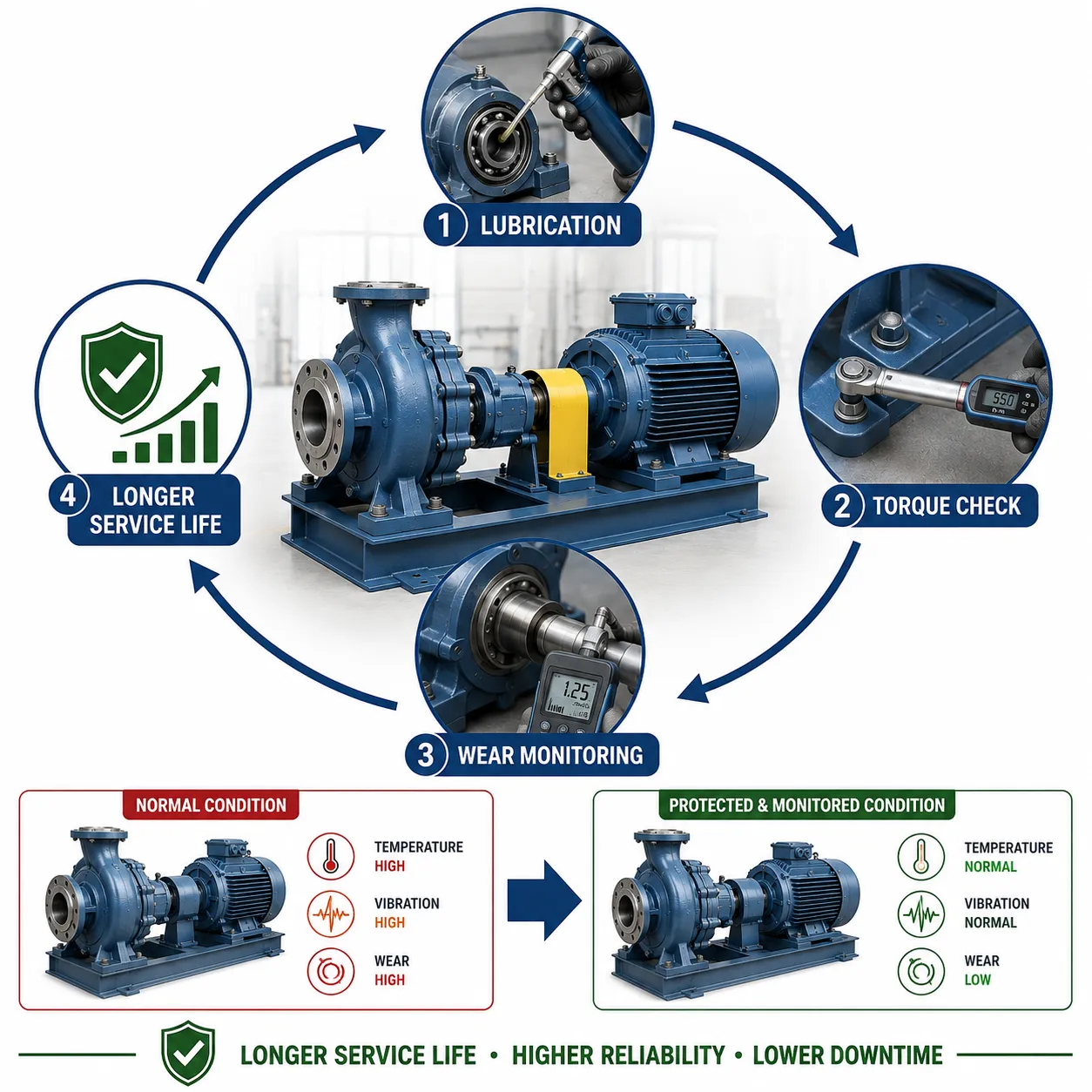
Three important controls are:
Lubrication
Lubrication reduces friction, wear and heat generation between moving surfaces.
Bolt-Torque Control
Correct bolt preload helps maintain the required integrity of bolted joints under operating loads and vibration.
Wear Monitoring
Wear monitoring identifies progressive material loss or dimensional changes before they become severe enough to compromise equipment performance.
Individually, each activity provides value. Collectively, they provide a more comprehensive asset-integrity strategy.
Key Concepts and Definitions
| Key concept | Definition | Asset integrity application |
|---|---|---|
| Asset integrity | Ability of an asset to perform its required function while maintaining required condition | Provides the overall framework for mechanical reliability |
| Preventive maintenance | Planned activity intended to reduce the likelihood of equipment deterioration or failure | Controls known degradation mechanisms |
| Lubrication | Application of an appropriate lubricant to reduce friction and wear | Protects moving interfaces |
| Lubricant condition | Physical and chemical state of lubricant during service | Indicates whether lubrication remains effective |
| Bolt torque | Applied rotational force used to achieve required fastener preload | Supports bolted-joint integrity |
| Preload | Initial tension established in a bolted joint | Maintains joint clamping force |
| Wear | Progressive material loss or dimensional change caused by mechanical interaction | Indicates component degradation |
| Wear monitoring | Systematic measurement or assessment of wear progression | Supports remaining-life and maintenance decisions |
| Condition monitoring | Collection and analysis of equipment-condition information | Identifies developing abnormalities |
| Equipment criticality | Relative importance of equipment to safety, quality, production or reliability | Determines maintenance and monitoring priority |
| Baseline | Initial verified condition used for future comparison | Provides reference for degradation trends |
| Maintenance history | Recorded evidence of previous maintenance activities and findings | Supports trend and recurrence analysis |
| Failure mode | Specific way an asset or component can fail to perform its function | Supports risk-based maintenance planning |
| Corrective action | Action taken to address an identified existing problem | Restores acceptable condition |
| Preventive action | Action intended to reduce the likelihood of future deterioration | Prevents recurrence or escalation |
| Verification | Evidence confirming that a maintenance activity achieved its intended outcome | Supports quality assurance and closure |
Establishing an Asset Integrity Programme
An effective programme should begin with a structured assessment of the equipment population.
The organisation should identify:
- Equipment types.
- Equipment locations.
- Critical components.
- Operating conditions.
- Known failure modes.
- Maintenance requirements.
- Inspection requirements.
- Lubrication requirements.
- Fastener requirements.
- Wear mechanisms.
- Previous failure history.
This information provides the foundation for establishing maintenance and inspection priorities.
Equipment Criticality Assessment
Not every machine requires the same level of asset-integrity control.
Criticality can be assessed using factors such as:
- Safety consequences.
- Production consequences.
- Quality consequences.
- Environmental consequences.
- Replacement cost.
- Availability of spare equipment.
- Repair time.
- Failure frequency.
- Operating conditions.
For example, a critical rotating machine supporting continuous production may require more frequent condition monitoring than a non-critical auxiliary machine.
Developing a Maintenance Register
A structured maintenance register can define the required activities for each asset.
A register may include:
- Asset identification.
- Equipment description.
- Criticality.
- Lubrication requirements.
- Torque-check requirements.
- Wear-monitoring requirements.
- Inspection frequency.
- Responsible person.
- Acceptance criteria.
- Previous results.
- Current condition.
- Corrective actions.
- Next inspection date.
This provides a controlled connection between asset requirements and maintenance execution.
Lubrication as an Asset-Integrity Control

Lubrication is one of the most important controls for equipment containing moving or contacting surfaces.
An appropriate lubricant can:
- Reduce friction.
- Reduce heat generation.
- Reduce surface wear.
- Protect against corrosion.
- Reduce direct metal-to-metal contact.
- Support smooth operation.
- Improve component service life.
However, lubrication effectiveness depends on more than simply adding lubricant.
The Importance of Correct Lubricant Selection
Lubricants must be suitable for the application.
Selection can depend on:
- Component type.
- Operating speed.
- Operating temperature.
- Load.
- Environmental exposure.
- Lubricant compatibility.
- Manufacturer requirements.
- Contamination risk.
An incorrect lubricant may reduce rather than improve equipment reliability.
Potential consequences include:
- Excessive friction.
- Overheating.
- Premature wear.
- Seal deterioration.
- Lubricant breakdown.
- Reduced bearing life.
Lubrication Frequency
Lubrication intervals should be established according to equipment requirements rather than applying one universal interval to all machinery.
Relevant considerations include:
- Operating hours.
- Speed.
- Load.
- Temperature.
- Environmental contamination.
- Lubricant type.
- Equipment criticality.
- Historical condition.
- Manufacturer recommendations.
A critical bearing operating continuously in a contaminated environment may require a different lubrication strategy from a lightly loaded auxiliary component.
Over-Lubrication
More lubricant does not necessarily mean better protection.
Over-lubrication can contribute to:
- Increased temperature.
- Churning losses.
- Seal problems.
- Lubricant leakage.
- Contamination.
- Bearing damage.
Therefore, lubrication quantities should be controlled according to the equipment’s technical requirements.
Under-Lubrication
Insufficient lubrication can result in:
- Increased friction.
- Increased temperature.
- Accelerated wear.
- Surface damage.
- Bearing degradation.
- Gear damage.
- Premature failure.
Under-lubrication should therefore be treated as a potential asset-integrity threat.
Lubricant Contamination
Lubricants can become contaminated by:
- Dust.
- Water.
- Metal particles.
- Process chemicals.
- Dirt.
- Degraded lubricant.
- Incorrect lubricant mixtures.
Contamination can accelerate component deterioration.
A structured programme should therefore consider lubricant cleanliness and condition where relevant.
Lubricant Condition Monitoring
Depending on equipment criticality, lubricant condition may be assessed through:
- Visual inspection.
- Sampling.
- Laboratory analysis.
- Particle analysis.
- Water contamination checks.
- Viscosity assessment.
- Wear-particle analysis.
The objective is to identify evidence of lubricant deterioration or component wear before a major failure occurs.
Practical Example: Bearing Lubrication
A production machine contains a critical bearing operating continuously.
Historical data indicate that bearing temperature increases when lubrication intervals are extended.
The asset-integrity programme responds by:
- Establishing a controlled lubrication interval.
- Recording lubrication activities.
- Monitoring bearing temperature.
- Reviewing lubricant condition.
- Comparing current measurements with historical trends.
The result is a more evidence-based maintenance strategy rather than simply lubricating the bearing whenever a problem becomes noticeable.
Bolt-Torque Management
Bolted joints are essential to many mechanical systems.
Examples include:
- Flanges.
- Equipment housings.
- Structural connections.
- Pipe supports.
- Machine assemblies.
- Coupling guards.
- Pressure-containing joints.
Correct bolt preload helps maintain joint integrity.
Understanding Torque and Preload
Torque is the rotational force applied during tightening. It is commonly used as a practical means of achieving a required fastener preload.
The relationship between torque and preload can be influenced by:
- Thread condition.
- Lubrication.
- Friction.
- Fastener material.
- Nut condition.
- Washer condition.
- Surface condition.
- Tightening method.
Therefore, torque values should be applied according to the relevant engineering requirements rather than assumed universally.
Consequences of Incorrect Torque
Under-torquing
Potential consequences include:
- Loss of joint clamping force.
- Joint movement.
- Vibration-related loosening.
- Leakage.
- Fretting.
- Fatigue.
- Joint separation.
Over-torquing
Potential consequences include:
- Fastener yielding.
- Thread damage.
- Excessive preload.
- Component distortion.
- Flange damage.
- Reduced joint reliability.
Both conditions can compromise asset integrity.
Controlled Torque Procedures
A professional torque-control procedure should define:
- Correct fastener identification.
- Required torque value.
- Tightening sequence.
- Tool requirements.
- Tool verification.
- Lubrication condition.
- Acceptance criteria.
- Recording requirements.
- Reinspection requirements where necessary.
Torque Tool Verification
Torque tools should be appropriately maintained and verified according to the applicable quality system and equipment requirements.
Records may include:
- Tool identification.
- Verification status.
- Verification date.
- Required range.
- Calibration or verification evidence.
- Person performing the work.
Using an unsuitable or unverified torque tool can undermine the reliability of the joint.
Tightening Sequence
For flanged or multi-bolt assemblies, tightening sequence can influence load distribution.
A controlled sequence may help:
- Distribute preload more evenly.
- Reduce localised distortion.
- Improve joint consistency.
- Support sealing performance.
The exact sequence should follow the applicable engineering or equipment requirements.
Bolt-Torque Inspection Records
A torque record can include:
- Equipment identification.
- Joint identification.
- Fastener size.
- Required torque.
- Actual torque where required.
- Tool identification.
- Date.
- Technician.
- Verification status.
- Acceptance result.
These records provide important QA/QC traceability.
Wear Monitoring
Wear is progressive material loss or surface degradation caused by mechanical interaction.
Common wear mechanisms include:
- Adhesive wear.
- Abrasive wear.
- Fretting.
- Erosive wear.
- Surface fatigue.
- Sliding wear.
- Rolling-contact wear.
The specific mechanism depends on the materials, loads, motion, lubrication and environment.
Why Wear Monitoring Is Important
Wear often develops gradually.
For example:
Initial wear → dimensional change → increased clearance → vibration → performance deterioration → component failure
Early detection provides an opportunity to intervene before the equipment reaches an unacceptable condition.
Wear Indicators
Potential indicators include:
- Increased vibration.
- Increased noise.
- Temperature changes.
- Increased clearance.
- Dimensional loss.
- Surface damage.
- Reduced efficiency.
- Increased lubricant contamination.
- Increased maintenance frequency.
These indicators should be interpreted in relation to equipment-specific requirements.
Dimensional Wear Monitoring
Dimensional measurements can be used to track:
- Shaft diameter.
- Bearing clearance.
- Gear tooth dimensions.
- Bush dimensions.
- Wear-pad thickness.
- Seal dimensions.
- Component thickness.
Repeated measurements provide a basis for identifying degradation trends.
Baseline Measurements
A baseline should be established where practical.
The baseline may record:
- Initial dimensions.
- Initial vibration.
- Initial temperature.
- Initial lubricant condition.
- Initial torque condition.
- Initial component appearance.
Future results can then be compared against the baseline.
Trend Analysis
A single measurement may provide limited information.
For example:
- Month 1: 0.20 mm wear.
- Month 2: 0.22 mm wear.
- Month 3: 0.25 mm wear.
- Month 4: 0.31 mm wear.
The increasing rate may be more important than the absolute value.
This is why trend analysis is central to proactive asset integrity.
Integrating Lubrication, Torque and Wear Monitoring
The greatest value comes when these activities are considered together.
For example:
Lubrication degradation → increased friction → increased temperature → accelerated wear
Similarly:
Incorrect bolt preload → joint movement → vibration → accelerated component wear
The asset-integrity programme should therefore avoid treating maintenance activities as isolated tasks.
Structured Asset Integrity Workflow
A practical workflow can be organised as follows:
Step 1: Identify Critical Assets
Determine which equipment requires enhanced integrity controls.
Step 2: Identify Failure Modes
Assess credible degradation mechanisms.
Step 3: Define Controls
Establish lubrication, torque and wear-monitoring requirements.
Step 4: Establish Baselines
Record initial equipment condition.
Step 5: Execute Planned Activities
Perform maintenance and inspections according to the programme.
Step 6: Record Results
Capture measurable findings and deviations.
Step 7: Analyse Trends
Compare current results with historical performance.
Step 8: Investigate Abnormalities
Assess emerging degradation.
Step 9: Implement Action
Complete corrective or preventive measures.
Step 10: Verify
Confirm that equipment condition has improved or remains acceptable.
Step 11: Review
Evaluate programme effectiveness.
Step 12: Improve
Update maintenance frequencies or controls where evidence supports change.
Asset Integrity Inspection Matrix
| Activity | Typical purpose | Evidence generated | Potential warning sign | Possible response |
|---|---|---|---|---|
| Lubrication inspection | Maintain moving-component protection | Lubrication record | Contamination or degradation | Investigate lubricant condition |
| Lubricant monitoring | Assess lubricant health and wear evidence | Analysis results | Increased particles | Inspect component condition |
| Bolt-torque verification | Maintain joint preload | Torque record | Low or inconsistent torque | Investigate joint condition |
| Visual inspection | Identify visible deterioration | Inspection report | Cracks, leakage or damage | Assess and repair |
| Dimensional monitoring | Identify wear progression | Measurement history | Increasing dimensional loss | Plan intervention |
| Vibration monitoring | Identify rotating degradation | Trend data | Increasing vibration | Investigate rotating equipment |
| Temperature monitoring | Identify friction or loading problems | Temperature trend | Progressive temperature increase | Assess lubrication/load/condition |
| Post-maintenance verification | Confirm maintenance effectiveness | Verification record | Continued abnormality | Reassess action |
Risk-Based Maintenance Frequency
Maintenance intervals should reflect equipment risk.
A critical machine may require:
- More frequent inspection.
- More detailed condition monitoring.
- Tighter documentation.
- Defined escalation criteria.
- More frequent lubricant assessment.
A lower-criticality asset may operate under a simpler programme.
This approach helps allocate maintenance resources where they provide the greatest reliability benefit.
Establishing Acceptance Criteria
Every inspection activity should have a meaningful acceptance basis.
Examples include:
- Required torque.
- Permitted wear.
- Acceptable vibration range.
- Lubricant condition requirements.
- Maximum dimensional deviation.
- Maximum temperature.
- Component-specific condition requirements.
Without acceptance criteria, inspection can become subjective.
Escalation Criteria
An integrity programme should define when a condition requires escalation.
Triggers may include:
- Rapid deterioration.
- Excessive wear.
- Repeated torque loss.
- Abnormal vibration.
- Rising temperature.
- Lubricant contamination.
- Recurrent leakage.
- Unexpected component damage.
- Failure of previous corrective action.
Escalation allows the organisation to respond before deterioration becomes a major failure.
Maintenance History and Reliability Analysis
Historical records provide valuable evidence for improving asset-integrity programmes.
Maintenance history can reveal:
- Repeated bearing failures.
- Frequent lubrication problems.
- Recurring loose fasteners.
- Accelerating wear.
- Repeated component replacements.
- Inadequate maintenance intervals.
This information can be used to adjust maintenance strategies.
Practical Case Study: Rotating Equipment
A critical pump has experienced repeated bearing replacements.
Historical records show:
- Increasing bearing temperature before failures.
- Inconsistent lubrication intervals.
- Periodic vibration increases.
- Evidence of lubricant contamination.
The asset-integrity team introduces:
- Controlled lubrication intervals.
- Lubricant-condition monitoring.
- Bearing temperature trending.
- Vibration monitoring.
- Defined escalation criteria.
The team then reviews the data periodically.
The objective is not simply to replace bearings more frequently. The objective is to identify and control the mechanisms causing premature bearing deterioration.
Practical Case Study: Bolted Flange
A process flange develops repeated minor leakage.
Investigation of maintenance records identifies inconsistent tightening practices.
The organisation introduces:
- Controlled torque values.
- Verified torque tools.
- Defined tightening sequences.
- Torque records.
- Post-maintenance inspection.
Subsequent monitoring shows improved joint consistency.
The example demonstrates how a structured torque-control programme can reduce recurring mechanical defects.
Practical Case Study: Wear Monitoring
A gearbox contains components susceptible to progressive wear.
Inspection records indicate increasing clearance over successive inspections.
Instead of waiting until the gearbox becomes noisy or fails, the engineering team:
- Establishes a wear trend.
- Defines intervention criteria.
- Reviews operating conditions.
- Plans component replacement.
- Verifies the condition after intervention.
This converts maintenance from reactive repair into proactive reliability management.
Documentation and Traceability
A strong asset-integrity programme requires reliable records.
Documentation should provide traceability between:
Asset → Inspection → Finding → Action → Verification → Historical trend
Records should be:
- Accurate.
- Complete.
- Legible.
- Traceable.
- Timely.
- Accessible to authorised personnel.
- Protected against uncontrolled alteration.
Digital Asset Integrity Management
Digital systems can improve the management of large equipment populations.
A digital system may provide:
- Automated maintenance schedules.
- Asset histories.
- Inspection reminders.
- Trend graphs.
- Defect tracking.
- Torque records.
- Lubrication records.
- Wear measurements.
- Action tracking.
However, technology does not replace engineering judgement. Poor data entered into an advanced system will still produce poor decision-making.
Key Performance Indicators
Asset-integrity programmes can be evaluated using indicators such as:
- Preventive maintenance completion rate.
- Overdue maintenance percentage.
- Recurring failure rate.
- Mean time between failures.
- Lubrication compliance.
- Torque-check compliance.
- Number of wear-related failures.
- Unplanned downtime.
- Corrective-action closure rate.
- Repeat defect frequency.
The selected KPIs should reflect the actual objectives and criticality of the asset population.
Common Programme Weaknesses
Treating lubrication as routine paperwork
A signed lubrication checklist does not demonstrate that the correct lubricant, quantity and method were used.
Ignoring lubricant contamination
Lubricant condition can provide important evidence about component health.
Using incorrect torque values
Torque should be based on the applicable engineering requirements.
Failing to verify torque tools
Tool condition and verification can influence measurement reliability.
Monitoring wear without analysing trends
Recording measurements without analysing progression limits the value of the programme.
Applying identical intervals to all equipment
Maintenance should reflect equipment criticality and degradation risk.
Closing actions without verification
An action is not necessarily effective simply because it has been completed.
Benefits of a Structured Asset Integrity Programme
A well-designed programme can provide:
- Extended machinery service life.
- Reduced mechanical failures.
- Lower maintenance costs.
- Improved equipment availability.
- Reduced unplanned downtime.
- Earlier failure detection.
- Better maintenance planning.
- Improved component reliability.
- Better QA/QC traceability.
- Improved safety performance.
- More consistent equipment condition.
- Better lifecycle cost management.
- Stronger engineering decision-making.
Continuous Improvement
Asset integrity should be continuously reviewed.
The review process can ask:
- Are lubrication intervals appropriate?
- Are recurring torque issues occurring?
- Are wear rates changing?
- Are preventive actions effective?
- Are inspection intervals suitable?
- Are failure modes changing?
- Are maintenance resources correctly prioritised?
Where evidence indicates a weakness, the programme should be revised.
Integrating the Programme with QA/QC
From a QA/QC perspective, asset integrity should be integrated with:
- Inspection and test plans.
- Maintenance procedures.
- Equipment records.
- Non-conformance management.
- Corrective actions.
- Root-cause analysis.
- Reliability engineering.
- Condition monitoring.
- Continuous improvement.
This creates a closed-loop management system rather than disconnected maintenance activities.
Professional Decision-Making Framework
When evaluating an asset-integrity requirement, the engineering team should consider:
Equipment criticality
How significant would failure be?
Failure mechanisms
What can cause deterioration?
Current condition
What evidence exists about the equipment’s present state?
Historical performance
Has the equipment experienced recurring problems?
Monitoring capability
Can deterioration be detected early?
Maintenance effectiveness
Have previous interventions controlled the problem?
Operating conditions
Are load, speed, temperature or environmental conditions changing?
Remaining service requirement
How long must the equipment continue to operate?
These factors help determine appropriate maintenance and inspection controls.
Conclusion
A structured asset integrity programme provides a systematic method for extending machinery lifespan while maintaining mechanical performance, reliability and quality. Lubrication, bolt-torque verification and wear monitoring are particularly valuable because they address common mechanisms of mechanical deterioration across rotating equipment, bolted assemblies, gears, bearings, shafts and other critical components. When these activities are performed according to defined requirements, recorded accurately and evaluated against historical trends, they provide an effective early-warning system for developing defects.
The strongest programmes do not treat lubrication, torque checks and wear measurements as isolated maintenance tasks. Instead, they connect these activities with equipment criticality, failure-mode analysis, condition monitoring, inspection data, maintenance history and corrective-action systems. This allows engineering teams to identify relationships between apparently minor abnormalities and larger reliability risks. For example, lubricant contamination may provide early evidence of bearing deterioration, repeated torque loss may indicate a joint-integrity problem, and accelerating dimensional wear may indicate that a component is approaching an intervention threshold.
Long-term asset integrity therefore depends on a continuous cycle of planning, inspection, measurement, analysis, intervention and verification. By establishing reliable baselines, applying appropriate acceptance criteria, analysing degradation trends and continuously improving maintenance strategies, organisations can reduce unplanned failures, improve equipment availability and extend useful mechanical service life. A data-driven asset-integrity programme ultimately supports safer, more reliable and more cost-effective mechanical systems throughout their operational lifecycle.
3. Analyse Long-Term Maintenance Records to Determine Whether Current Servicing Schedules Maintain Mechanical Assets at Peak Efficiency
Long-term maintenance records provide one of the most valuable sources of evidence for evaluating the effectiveness of mechanical asset-management strategies. A servicing schedule may appear appropriate because inspections and maintenance activities are being completed on time, but completion alone does not demonstrate that the equipment is actually operating efficiently or reliably. A professional mechanical QA/QC and asset-integrity approach must examine historical maintenance records alongside equipment performance, failure history, condition-monitoring results, downtime, component replacement, energy or operating trends, recurring defects and corrective actions. This allows engineering teams to determine whether the current servicing frequency is genuinely controlling deterioration or simply documenting routine activity.
For mechanical systems, the objective of maintenance analysis is not necessarily to maximise the amount of maintenance performed. Excessive servicing can consume labour, spare parts and production time without producing proportional reliability benefits, while insufficient servicing can allow wear, lubrication degradation, misalignment, corrosion, fatigue or other failure mechanisms to progress. The appropriate maintenance schedule is therefore one that is supported by evidence and remains suitable for the actual operating conditions of the asset. Analysing long-term records allows engineering professionals to identify whether servicing intervals are too short, too long or appropriately matched to equipment behaviour.
Understanding Long-Term Maintenance Analysis
Long-term maintenance analysis is the systematic examination of historical servicing, inspection and performance information to determine whether maintenance activities are achieving their intended objectives.
The analysis should answer questions such as:
- Is equipment reliability improving?
- Are breakdowns becoming less frequent?
- Are recurring defects being controlled?
- Are maintenance intervals appropriate?
- Is equipment performance remaining stable?
- Are components lasting as expected?
- Are maintenance activities preventing failures?
- Are corrective actions effective?
- Are servicing costs increasing without corresponding performance improvements?
- Are operating conditions changing faster than the maintenance strategy?
The emphasis is therefore on evidence-based evaluation rather than simply checking whether maintenance tasks have been completed.
Key Concepts and Definitions
| Key concept | Definition | Application in maintenance analysis |
|---|---|---|
| Maintenance record | Documented evidence of servicing, inspection, repair or intervention | Provides historical evidence for performance evaluation |
| Preventive maintenance | Planned maintenance intended to reduce failure probability | Used to control known degradation mechanisms |
| Corrective maintenance | Maintenance performed to restore an identified defective condition | Indicates failures or abnormalities requiring intervention |
| Maintenance interval | Planned time or operating period between servicing activities | Determines servicing frequency |
| Maintenance effectiveness | Degree to which maintenance achieves its intended reliability or performance objective | Determines whether schedules require adjustment |
| Equipment availability | Proportion of required time that equipment is capable of operating | Indicates operational impact of maintenance and failures |
| Reliability | Probability that equipment performs its required function for a specified period under stated conditions | Supports evaluation of asset performance |
| Failure frequency | Number or rate of equipment failures over a defined period | Helps identify reliability trends |
| Mean Time Between Failures (MTBF) | Average operating time between applicable failures | Useful indicator for reliability trend analysis |
| Mean Time To Repair (MTTR) | Average time required to restore equipment after failure | Indicates repair efficiency |
| Downtime | Period when equipment is unavailable for required operation | Shows operational consequences of failures and maintenance |
| Recurring defect | Similar defect repeatedly occurring on the same or related equipment | May indicate ineffective maintenance or unresolved root cause |
| Maintenance backlog | Outstanding maintenance tasks that remain incomplete | Can indicate resource or scheduling weaknesses |
| Condition monitoring | Monitoring equipment parameters to identify developing changes | Provides evidence for maintenance interval decisions |
| Baseline | Reference condition established for comparison | Supports identification of deterioration |
| Trend analysis | Examination of changes in data over time | Identifies improvement, deterioration or stability |
| Peak efficiency | Desired operating performance under defined conditions | Provides a benchmark for evaluating maintenance effectiveness |
Why Long-Term Records Matter
A single maintenance event provides limited information. A long-term record reveals patterns.
For example, one bearing replacement does not necessarily indicate that the servicing schedule is inadequate. However, if the same bearing type requires replacement every three months despite a scheduled six-month servicing interval, the historical evidence suggests that the maintenance strategy requires investigation.
Long-term records can reveal:
- Repeated component failures.
- Increasing maintenance frequency.
- Rising repair costs.
- Increasing downtime.
- Changes in vibration.
- Increasing temperature.
- Lubrication-related problems.
- Repeated alignment defects.
- Progressive wear.
- Increasing inspection findings.
- Declining equipment output.
These trends provide evidence for determining whether the current servicing strategy is effective.
Establishing the Purpose of the Analysis
Before analysing records, the engineering team should define what it is trying to determine.
Possible objectives include:
- Determine whether servicing intervals are appropriate.
- Identify recurring mechanical failures.
- Evaluate maintenance effectiveness.
- Determine whether equipment reliability is improving.
- Identify unnecessary maintenance activities.
- Identify under-maintained equipment.
- Compare maintenance performance between similar assets.
- Establish evidence for changing servicing intervals.
- Support reliability improvement initiatives.
A clearly defined objective prevents the analysis from becoming a simple collection of historical statistics.
Types of Maintenance Records to Analyse
A comprehensive analysis may include:
- Preventive maintenance records.
- Corrective maintenance records.
- Inspection reports.
- Lubrication records.
- Torque-check records.
- Wear measurements.
- Vibration measurements.
- Temperature records.
- Component replacement records.
- Failure reports.
- Breakdown records.
- Downtime records.
- Maintenance work orders.
- Spare-parts consumption.
- Non-conformance reports.
- Root-cause investigations.
- Calibration records.
- Equipment performance data.
The value increases when these information sources can be connected to the same asset.
Maintenance History Structure
A useful maintenance history should identify:
- Equipment identification.
- Maintenance date.
- Equipment operating hours.
- Maintenance type.
- Work performed.
- Component affected.
- Defect identified.
- Condition before intervention.
- Parts replaced.
- Labour or resource requirements.
- Post-maintenance condition.
- Follow-up requirements.
- Equipment return-to-service date.
This enables meaningful comparison between maintenance activities and subsequent equipment performance.
Analysing Maintenance Frequency
The first stage is often to compare planned and actual servicing frequency.
For example:
Planned service: every 1,000 operating hours
Actual service: every 650–800 hours due to recurring problems
This discrepancy is important.
If maintenance is repeatedly brought forward because the equipment deteriorates before the planned interval, the original schedule may not adequately reflect actual operating conditions.
Conversely, if inspections consistently show excellent condition at every scheduled service, the organisation may have evidence to evaluate whether the interval could be optimised.
Any change should remain controlled and technically justified.
Planned Versus Unplanned Maintenance
One useful indicator is the relationship between planned and unplanned maintenance.
A healthy maintenance strategy generally aims to reduce unexpected interventions where practical.
The records should therefore distinguish:
- Planned preventive work.
- Condition-based interventions.
- Corrective work.
- Emergency breakdown work.
A high proportion of emergency interventions may indicate that the servicing strategy is not adequately controlling equipment degradation.
Analysing Failure Frequency
Failure frequency should be examined over an appropriate period.
For example:
| Period | Failures | Operating hours | General trend |
|---|---|---|---|
| Year 1 | 12 | 8,000 | High |
| Year 2 | 10 | 8,200 | Improving |
| Year 3 | 7 | 8,400 | Improving |
| Year 4 | 8 | 8,300 | Slight deterioration |
The raw number of failures should not be considered alone. Operating exposure and equipment utilisation should also be considered.
Analysing MTBF
Mean Time Between Failures can help assess reliability trends.
A simplified calculation is:
MTBF = Total operating time / Number of applicable failures
For example:
If equipment operates for 6,000 hours and experiences 6 applicable failures:
MTBF = 6,000 / 6 = 1,000 hours
If subsequent analysis shows:
MTBF = 1,300 hours
this may indicate improved reliability, assuming the data definitions and operating conditions remain comparable.
MTBF should not be interpreted in isolation. Changes in failure classification, operating conditions or maintenance practices can affect the result.
Analysing MTTR
Mean Time To Repair provides information about maintenance restoration performance.
A simplified calculation is:
MTTR = Total repair time / Number of applicable repairs
A decreasing MTTR may indicate that:
- Fault diagnosis has improved.
- Spare parts are more readily available.
- Maintenance procedures are more effective.
- Technician capability has improved.
- Equipment access has improved.
However, a low MTTR does not necessarily mean the maintenance strategy is effective if failures are occurring excessively often.
Evaluating Equipment Availability
Availability provides another useful measure.
A simplified conceptual relationship is:
Availability = Operating time / Required operating time
Maintenance records can show whether downtime is increasing or decreasing.
For example, an equipment unit may have excellent repair speed but poor overall availability because failures occur frequently. This demonstrates why multiple indicators should be analysed together.
Maintenance Records and Peak Efficiency
Peak efficiency should be defined according to the equipment’s intended function.
Depending on the asset, relevant measures could include:
- Production throughput.
- Mechanical output.
- Energy consumption.
- Cycle time.
- Operating temperature.
- Vibration.
- Pressure stability.
- Dimensional accuracy.
- Component wear.
- Product quality.
- Availability.
The analysis should compare these indicators with established operating requirements rather than assuming that a machine is efficient simply because it remains operational.
Practical Example: Pump Maintenance
A process pump is serviced every six months.
Historical records show:
- Increasing vibration during months four and five.
- Bearing temperature increases before the next scheduled service.
- Occasional seal leakage.
- Two bearing replacements within eighteen months.
The engineering team reviews the records and identifies that deterioration begins before the six-month service interval.
This suggests that the existing schedule may require review.
Possible responses include:
- Increased condition monitoring.
- Revised lubrication controls.
- Investigation of alignment.
- Adjustment of maintenance intervals.
- Review of bearing selection.
- Evaluation of operating conditions.
The correct response should be based on evidence rather than simply shortening every maintenance interval.
Practical Example: Gearbox Servicing
A gearbox is serviced every 2,000 operating hours.
Historical data show that:
- Lubricant condition remains acceptable at 2,000 hours.
- Vibration remains stable.
- No significant wear is detected.
- No gearbox failures occur.
- Previous servicing records show consistent condition.
The evidence may indicate that the current servicing interval is controlling degradation effectively.
The organisation may continue the schedule while maintaining condition monitoring and periodically reviewing the evidence.
The lesson is important: maintenance optimisation should not automatically mean increasing or decreasing the frequency. It means matching the frequency to demonstrated equipment behaviour.
Identifying Recurring Failures
Recurring failures are among the strongest indicators that a servicing strategy may require review.
Examples include:
- Repeated bearing failure.
- Repeated seal leakage.
- Recurring coupling misalignment.
- Repeated gear wear.
- Frequent fastener loosening.
- Repeated lubrication contamination.
- Recurring overheating.
The analysis should investigate whether the maintenance intervention is addressing the root cause or merely restoring the equipment temporarily.
Maintenance and Root-Cause Analysis
Historical maintenance records can support root-cause analysis by answering:
- When did the defect first appear?
- How frequently has it occurred?
- Which components are affected?
- What maintenance was previously performed?
- Did the defect return?
- Were operating conditions different?
- Was the same spare part used?
- Did the failure occur shortly after servicing?
This can distinguish between isolated events and systemic problems.
Evaluating Maintenance Effectiveness
Maintenance effectiveness should be evaluated using before-and-after evidence.
For example:
Before maintenance
- High vibration.
- Elevated temperature.
- Increased lubricant contamination.
- Reduced output.
After maintenance
- Stable vibration.
- Normal temperature.
- Acceptable lubricant condition.
- Restored output.
If the improvement is sustained, the intervention provides stronger evidence of effectiveness.
Temporary Improvement Versus Sustainable Improvement
A critical QA/QC distinction is whether maintenance produces temporary or lasting improvement.
A component replacement may restore performance for several weeks, but if the same component fails repeatedly, the maintenance strategy may not be controlling the underlying cause.
Sustainable improvement should demonstrate:
- Reduced recurrence.
- Stable performance.
- Appropriate component life.
- Reduced unplanned downtime.
- Controlled degradation.
Analysing Lubrication Records
Lubrication records should be evaluated for:
- Correct lubricant.
- Correct quantity.
- Correct interval.
- Contamination.
- Missed lubrication tasks.
- Repeated lubrication-related defects.
- Changes in lubricant condition.
For example, if bearings repeatedly overheat after lubrication intervals are extended, the maintenance history may demonstrate a relationship between servicing frequency and equipment performance.
Analysing Wear Records
Wear measurements can provide strong evidence of maintenance effectiveness.
Suppose a component has the following measurements:
- Initial wear: 0.10 mm.
- Six months: 0.14 mm.
- Twelve months: 0.19 mm.
- Eighteen months: 0.28 mm.
The increasing rate of dimensional loss should be examined.
Potential questions include:
- Has the operating load changed?
- Has lubrication deteriorated?
- Is alignment correct?
- Has the component reached an intervention threshold?
- Is the current inspection interval sufficient?
Analysing Vibration Records
Vibration trends are particularly useful for rotating machinery.
Historical analysis may identify:
- Stable vibration.
- Gradual increase.
- Sudden increase.
- Repeated peaks.
- Changes after maintenance.
- Changes under particular loads.
If vibration repeatedly increases before scheduled maintenance, condition-based intervention may be more appropriate than relying solely on fixed intervals.
Analysing Temperature Records
Temperature trends can indicate:
- Lubrication problems.
- Bearing deterioration.
- Increased friction.
- Cooling problems.
- Overloading.
The engineering team should compare temperature against:
- Historical baseline.
- Equipment operating load.
- Ambient conditions.
- Speed.
- Maintenance history.
This avoids interpreting an isolated measurement incorrectly.
Analysing Spare-Parts Consumption
Spare-parts consumption can provide another indication of maintenance effectiveness.
Repeated consumption of:
- Bearings.
- Seals.
- Couplings.
- Gears.
- Fasteners.
- Lubricants.
may indicate recurring degradation.
However, high spare-parts consumption does not automatically prove poor maintenance. Equipment age, utilisation and planned replacement strategy should also be considered.
Maintenance Cost Analysis
Cost should be evaluated alongside reliability.
Useful categories include:
- Preventive maintenance cost.
- Corrective maintenance cost.
- Emergency repair cost.
- Spare-parts cost.
- Labour cost.
- Downtime cost.
- Inspection cost.
A maintenance schedule may have a higher preventive-maintenance cost but lower overall lifecycle cost if it significantly reduces major failures.
Maintenance Interval Optimisation
Maintenance intervals should be reviewed using evidence from:
- Failure history.
- Condition monitoring.
- Wear rates.
- Lubricant condition.
- Operating hours.
- Equipment criticality.
- Manufacturer requirements.
- Historical maintenance effectiveness.
Any proposed interval change should be controlled through appropriate technical review.
Signs of Under-Maintenance
Potential indicators include:
- Increasing failures.
- Increasing emergency work.
- Rising vibration.
- Increasing wear.
- Recurring lubrication problems.
- Increasing downtime.
- Shorter component life.
- Repeated overheating.
These indicators may suggest that servicing frequency or maintenance quality requires improvement.
Signs of Over-Maintenance
Potential indicators may include:
- Frequent interventions with little measurable benefit.
- Stable equipment condition despite repeated early servicing.
- High maintenance labour consumption.
- Excessive component disturbance.
- Unnecessary replacement of healthy components.
- Increased maintenance-related defects.
Over-maintenance can itself introduce risk because unnecessary intervention can create opportunities for incorrect assembly, contamination, damage or human error.
Balanced Maintenance Strategy
The objective should therefore be:
Right maintenance + right frequency + right method + right evidence
rather than simply:
More maintenance = better reliability
A mature maintenance strategy balances:
- Reliability.
- Cost.
- Equipment condition.
- Production requirements.
- Safety.
- Quality.
- Maintenance resources.
Maintenance Schedule Review Process
A structured review can follow these steps.
Step 1: Define the asset
Identify equipment, critical components and intended function.
Step 2: Collect historical records
Gather maintenance, inspection, failure and performance data.
Step 3: Validate data
Check whether records are complete, consistent and comparable.
Step 4: Establish baseline performance
Determine normal operating behaviour.
Step 5: Analyse trends
Review failures, downtime, wear, vibration, temperature and other indicators.
Step 6: Compare planned and actual maintenance
Identify deviations from scheduled intervals.
Step 7: Evaluate effectiveness
Determine whether maintenance is preventing deterioration.
Step 8: Identify recurring problems
Investigate repeated failures and interventions.
Step 9: Review the servicing interval
Determine whether evidence supports maintaining or modifying the interval.
Step 10: Implement controlled changes
Update the maintenance programme where technically justified.
Step 11: Verify results
Monitor post-change performance.
Step 12: Continue review
Repeat the evaluation periodically.
Data Quality in Maintenance Analysis
Poor-quality records can produce misleading conclusions.
Maintenance data should therefore be:
- Accurate.
- Complete.
- Consistent.
- Time-stamped.
- Traceable to the correct asset.
- Based on defined failure categories.
- Comparable across periods.
For example, if one year records minor bearing defects as failures while another year does not, MTBF comparisons may become misleading.
Normalising Data
Historical comparisons should account for changes in:
- Operating hours.
- Production volume.
- Equipment utilisation.
- Environmental conditions.
- Operating load.
- Equipment configuration.
For example, ten failures during 10,000 operating hours may represent a different reliability condition from ten failures during 2,000 operating hours.
Case Study: Evaluating a Maintenance Schedule
Background
A manufacturing facility services a critical rotating machine every 1,000 operating hours.
Over three years, maintenance records show:
- Increasing bearing replacements.
- Increasing vibration before servicing.
- More frequent emergency interventions.
- Rising downtime.
- Increasing lubricant contamination.
Analysis
The engineering team compares:
- Maintenance intervals.
- Bearing life.
- Vibration trends.
- Lubricant results.
- Failure dates.
- Operating hours.
The analysis identifies that degradation often becomes measurable before the planned servicing point.
Engineering Response
The organisation introduces:
- More frequent condition monitoring.
- Improved lubrication controls.
- Targeted bearing inspections.
- Root-cause investigation.
- Defined intervention thresholds.
The servicing strategy becomes more condition-informed.
Result
The objective is to intervene based on evidence of deterioration rather than relying solely on a fixed calendar or operating-hour interval.
Case Study: Avoiding Unnecessary Maintenance
A second machine has been serviced every 500 operating hours for several years.
Historical records show:
- Stable vibration.
- Stable temperature.
- No significant wear.
- No recurring failures.
- Consistently acceptable lubricant condition.
The engineering team reviews the evidence and confirms that the existing schedule is effective.
Rather than automatically increasing or reducing maintenance frequency, the organisation maintains the established strategy while continuing periodic review.
This demonstrates the importance of evidence-based maintenance optimisation.
Key Performance Indicators for Maintenance Analysis
A maintenance-performance dashboard may include:
- Preventive maintenance completion rate.
- Corrective maintenance percentage.
- Emergency maintenance percentage.
- MTBF.
- MTTR.
- Equipment availability.
- Unplanned downtime.
- Repeat failure rate.
- Maintenance backlog.
- Spare-parts consumption.
- Lubrication compliance.
- Inspection compliance.
No single KPI should be used as the sole measure of maintenance effectiveness.
Interpreting KPI Relationships
Consider the following situation:
- MTBF increases.
- MTTR decreases.
- Unplanned downtime decreases.
- Recurring failures decrease.
This combination provides stronger evidence of improved maintenance effectiveness than any one indicator alone.
Conversely:
- Preventive maintenance completion = high.
- MTBF = declining.
- Emergency maintenance = increasing.
This indicates that completing planned maintenance tasks does not necessarily mean the programme is effective.
Connecting Maintenance Records with Asset Integrity
Maintenance history should feed directly into asset-integrity decision-making.
For example:
Maintenance records → Failure trends → Risk assessment → Maintenance strategy → Condition monitoring → Verification
This creates a closed-loop process.
Continuous Improvement
Maintenance schedules should not remain unchanged indefinitely.
Periodic review should consider:
- New failure mechanisms.
- Changes in operating conditions.
- Equipment modifications.
- New monitoring technology.
- Updated manufacturer information.
- Historical performance.
- Inspection findings.
- Recurring defects.
The programme should evolve according to evidence.
Common Analytical Mistakes
Looking only at maintenance completion
Completed tasks do not prove equipment is performing effectively.
Ignoring failures between services
Unplanned failures are important evidence about servicing effectiveness.
Using raw failure counts without exposure
Operating hours and utilisation should be considered.
Ignoring recurring defects
Repeated failures often provide the strongest indication of an unresolved problem.
Changing intervals without evidence
Maintenance schedules should be modified through controlled engineering review.
Overlooking maintenance-induced defects
Frequent intervention can sometimes create new problems.
Ignoring operating-condition changes
Higher loads, temperatures or speeds can alter degradation rates.
Benefits of Long-Term Maintenance Record Analysis
A structured analysis can provide:
- Better maintenance scheduling.
- Earlier failure detection.
- Improved equipment reliability.
- Reduced unplanned downtime.
- Longer component service life.
- Lower lifecycle costs.
- Better spare-parts planning.
- Improved maintenance resource allocation.
- Stronger asset-integrity decisions.
- Better QA/QC traceability.
- Improved continuous improvement.
- More reliable production performance.
Professional QA/QC Perspective
From a mechanical QA/QC perspective, maintenance records provide objective evidence of whether equipment controls are working in practice. A documented maintenance schedule represents the planned control, while historical performance demonstrates whether that control is effective under actual operating conditions.
The engineering professional should therefore compare planned requirements with actual outcomes. If recurring defects continue despite full maintenance compliance, the issue may not be workforce compliance; the maintenance strategy itself may require reassessment.
This distinction is particularly important in quality management because a process can be followed correctly while still being technically ineffective.
Recommended Review Matrix
| Evaluation area | Historical evidence | Question to assess | Possible conclusion |
|---|---|---|---|
| Failure frequency | Breakdown records | Are failures increasing? | Review maintenance strategy |
| MTBF | Operating and failure data | Is reliability improving? | Continue or revise controls |
| MTTR | Repair records | Are repairs becoming faster? | Assess maintenance efficiency |
| Downtime | Production records | Is availability improving? | Evaluate overall effectiveness |
| Wear | Inspection measurements | Is degradation accelerating? | Increase monitoring or intervene |
| Lubrication | Service and analysis records | Is lubrication controlling deterioration? | Adjust lubrication strategy |
| Vibration | Condition data | Is rotating condition stable? | Maintain or investigate |
| Temperature | Trend records | Is thermal performance stable? | Investigate developing problems |
| Recurring defects | Corrective-action records | Are defects returning? | Perform root-cause analysis |
| Maintenance backlog | Work-order records | Are tasks being completed? | Review resources and priorities |
Conclusion
Long-term maintenance records provide an essential evidence base for determining whether current servicing schedules are successfully maintaining mechanical assets at the required level of reliability and efficiency. A schedule should not be considered effective simply because planned tasks are completed on time. Its effectiveness must be demonstrated through measurable outcomes such as stable equipment condition, reduced failure frequency, acceptable wear rates, improved availability, controlled downtime, appropriate component life and a reduction in recurring defects.
A professional analysis combines maintenance history with condition-monitoring information, inspection results, operating hours, failure records, downtime, lubricant condition, vibration, temperature, wear measurements and component replacement history. This allows engineers to distinguish between effective preventive maintenance, under-maintenance and potentially unnecessary over-maintenance. Metrics such as MTBF, MTTR, availability, repeat-failure rate and preventive-maintenance compliance can support the analysis, but they should always be interpreted in context and against reliable, comparable data.
The most effective maintenance strategy is therefore dynamic and evidence-based. Historical records should be periodically reviewed to determine whether servicing intervals remain appropriate as equipment ages, operating conditions change and new degradation patterns emerge. Where evidence demonstrates deterioration before scheduled maintenance, the organisation may need stronger condition monitoring or revised intervention intervals. Where equipment consistently remains in excellent condition, the existing strategy can be validated rather than changed unnecessarily. Through this continuous cycle of data collection, analysis, engineering judgement, controlled intervention and verification, organisations can improve mechanical reliability, extend asset service life, reduce unplanned downtime and maintain high-quality performance throughout the operational lifecycle.