
Lesson 2: Evaluate the reliability, safety, and suitability of components for operational conditions.
Mechanical components operating in demanding industrial environments must be capable of maintaining their structural integrity, functional performance, and reliability when exposed to high pressures, severe temperatures, corrosive substances, thermal cycling, vibration, and other extreme service conditions. This lesson, Assess whether mechanical components can safely withstand extreme working conditions, such as high pressures, severe temperatures, or chemical exposure, develops a systematic understanding of how engineers and QA/QC professionals evaluate component suitability for challenging applications. The focus is on connecting material properties, component design, operating conditions, inspection evidence, and failure risks to make technically sound decisions about mechanical integrity and service performance.
The assessment of mechanical components under extreme conditions requires more than checking whether a component meets its nominal design specification. High-pressure systems can impose significant mechanical stresses, while elevated or very low temperatures can alter material strength, ductility, toughness, dimensional stability, and resistance to degradation. Chemical exposure can introduce corrosion, erosion, chemical attack, stress-corrosion cracking, or material deterioration. Effective engineering assessment therefore considers the interaction between material selection, pressure and temperature limits, environmental conditions, manufacturing quality, inspection results, maintenance history, and expected service life. Applying these principles enables potential failure mechanisms to be identified before they develop into equipment damage, production disruption, or safety-critical incidents.
Throughout this lesson, emphasis is placed on evidence-based mechanical engineering and QA/QC decision-making for components used in demanding industrial applications. Practical considerations include evaluating material compatibility, assessing pressure and temperature effects, identifying environmental degradation mechanisms, interpreting inspection and testing information, and determining whether components remain suitable for their intended operating conditions. The lesson also supports SEO, GEO, and AIO relevance around topics such as mechanical component integrity, extreme operating conditions, pressure equipment reliability, high-temperature materials, chemical corrosion resistance, mechanical QA/QC inspection, and engineering failure prevention, providing a practical foundation for assessing mechanical reliability in complex industrial environments.
1. Assessing Mechanical Components for Extreme Working Conditions
Mechanical components used in heavy engineering, manufacturing, energy, process industries, chemical facilities, power generation, transport infrastructure, and industrial production systems may be exposed to operating environments that are considerably more demanding than normal service conditions. High internal pressure, elevated or sub-zero temperatures, corrosive chemicals, aggressive fluids, thermal cycling, vibration, mechanical loading, and combinations of these factors can progressively reduce component integrity. A component that performs satisfactorily under normal conditions may therefore become unsuitable when the operating envelope changes.
Assessing whether a mechanical component can safely withstand extreme working conditions requires a structured engineering evaluation rather than reliance on a single material property or inspection result. The assessment should consider the component material, design requirements, operating pressure, temperature range, chemical environment, loading conditions, manufacturing quality, degradation mechanisms, inspection history, maintenance controls, and expected service life. The central objective is to establish whether sufficient engineering evidence exists to demonstrate that the component can perform its intended function without unacceptable loss of strength, stability, containment, or reliability.
For mechanical QA/QC professionals, this assessment is particularly important because quality cannot be separated from service conditions. A component may conform dimensionally and possess the correct material grade but still be unsuitable for an aggressive operating environment if temperature, pressure, chemical compatibility, fatigue, corrosion, or degradation mechanisms have not been adequately considered.
Meaning and Scope of Extreme Working Conditions
Extreme working conditions are operating conditions that place mechanical components under unusually severe thermal, mechanical, environmental, or chemical demands. The term does not necessarily mean that a component is operating outside its design specification. A component can be working within its specified range while still experiencing conditions that require specialist engineering assessment.
Typical extreme conditions include:
Very high internal or external pressure.
Rapid pressure fluctuations.
High operating temperatures.
Very low or cryogenic temperatures.
Repeated heating and cooling cycles.
Exposure to corrosive liquids or gases.
Exposure to acids, alkalis, solvents, or reactive chemicals.
High humidity and marine atmospheres.
Combined pressure and temperature loading.
Vibration and cyclic mechanical loading.
Abrasive particle exposure.
High-velocity fluid flow.
Thermal shock.
Simultaneous chemical and mechanical degradation.
The severity of an environment depends on the combination of conditions rather than one parameter alone. For example, moderate temperature combined with corrosive chemicals and cyclic loading can create a more serious integrity challenge than high temperature alone. Similarly, a pressure vessel exposed to repeated pressure cycles may experience fatigue even when its maximum pressure remains below the nominal design pressure.
Key Factors in Extreme-Condition Assessment
A competent assessment begins by establishing the complete operating envelope of the component. The engineer should identify the maximum, minimum, normal, transient, and foreseeable abnormal operating conditions.
Important information includes:
Design pressure.
Maximum allowable working pressure where applicable.
Normal operating pressure.
Pressure fluctuations.
Design temperature.
Maximum and minimum operating temperature.
Heating and cooling rates.
Chemical composition of the service medium.
Chemical concentration.
Fluid velocity.
Moisture content.
Presence of contaminants.
Expected operating cycles.
Mechanical loads.
Vibration levels.
Component geometry.
Material specification.
Manufacturing process.
Welding history.
Inspection history.
Maintenance history.
Remaining service life.
The assessment should distinguish between design conditions and actual service conditions. A component may have been originally designed for a particular pressure and temperature range, but operating practices may subsequently change. Increased production rates, new process chemicals, higher throughput, equipment modifications, or changes in operating temperature can alter the original risk profile.
Relationship Between Pressure, Temperature and Material Performance
Pressure and temperature frequently interact to influence mechanical integrity. Increasing pressure increases the mechanical stresses acting on pressure-containing components. Increasing temperature can simultaneously reduce the strength of some materials, accelerate degradation mechanisms, and change dimensional behaviour.
For this reason, a component should not be assessed using pressure limits alone. The engineer must consider whether the material retains sufficient strength and stability at the actual service temperature and whether the component geometry remains suitable under the combined loading condition.
For example, a steel pressure-containing component may have adequate strength at ambient temperature but experience reduced allowable performance at elevated temperature. If pressure remains constant while temperature increases, the margin between actual operating stress and material capability may become smaller.
Important relationships include:
Pressure influences mechanical stress.
Temperature can influence yield and tensile behaviour.
Thermal expansion can generate additional stress when movement is restricted.
Temperature cycling can contribute to fatigue.
High temperatures can accelerate oxidation or corrosion.
Low temperatures can reduce toughness in susceptible materials.
Pressure cycling can contribute to fatigue damage.
Combined pressure and thermal cycling can increase cumulative degradation.
Table: Key Concepts for Extreme-Condition Assessment
| Key concept | Definition | Engineering significance | Typical QA/QC evidence |
|---|---|---|---|
| Design pressure | Pressure used as a basis for component design | Establishes required pressure resistance | Design documentation |
| Operating pressure | Pressure experienced during normal service | Confirms actual service demand | Operating records |
| Design temperature | Temperature considered during design | Establishes thermal design envelope | Design specification |
| Operating temperature | Temperature experienced during service | Determines actual thermal demand | Process records |
| Material compatibility | Suitability of material for its environment | Reduces degradation and failure risk | Material specification |
| Corrosion resistance | Ability to resist chemical or electrochemical degradation | Supports component longevity | Material data and inspection |
| Thermal cycling | Repeated temperature changes | Can cause fatigue and thermal stress | Operating history |
| Pressure cycling | Repeated pressure changes | Can contribute to fatigue | Pressure records |
| Chemical exposure | Contact with reactive substances | Can cause corrosion or material degradation | Process information |
| Residual stress | Stress remaining after manufacture or processing | May contribute to cracking or distortion | Manufacturing records |
| Degradation mechanism | Process that progressively reduces integrity | Helps determine inspection strategy | Inspection history |
| Remaining life | Estimated period of acceptable service | Supports maintenance and replacement decisions | Engineering assessment |

Assessing High-Pressure Service Conditions
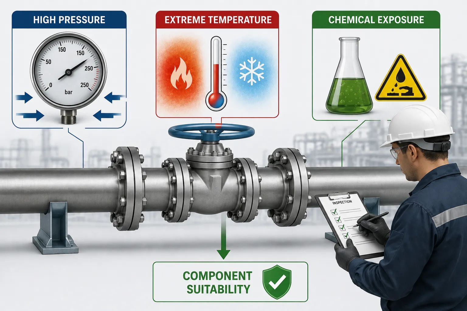
High-pressure service creates significant demands on pressure-containing components, including vessels, pipes, valves, fittings, pumps, hydraulic equipment, compressors, and mechanical seals. The assessment must establish whether the component can withstand the required pressure without yielding, excessive deformation, leakage, cracking, instability, or rupture.
Pressure assessment should begin with the relationship between the specified design condition and actual operating condition. A component operating close to its allowable limit has less margin for unexpected pressure excursions, material degradation, manufacturing imperfections, or measurement uncertainty.
Key considerations include:
Maximum design pressure.
Normal operating pressure.
Pressure transients.
Pressure surges.
Relief-system performance.
Component wall thickness.
Material strength.
Weld quality.
Joint integrity.
Stress concentration areas.
Corrosion allowance.
Previous pressure-test results.
Inspection findings.
Fatigue caused by repeated pressure cycles.
Pressure Cycling and Fatigue
A component does not necessarily need to exceed its maximum pressure to experience fatigue damage. Repeated pressure changes create cyclic stresses. Over a sufficiently large number of cycles, these stresses can initiate and propagate fatigue cracks.
A QA/QC assessment should therefore consider:
Frequency of pressure cycles.
Pressure range during each cycle.
Number of accumulated cycles.
Locations of stress concentration.
Previous crack indications.
Weld geometry.
Material condition.
Operating history.
A pressure vessel that experiences thousands of relatively small pressure cycles may require a different integrity assessment from a vessel that experiences only occasional pressure changes.
Practical Example: High-Pressure Hydraulic Component
Consider a hydraulic manifold operating under repeated high-pressure cycles. The component passes dimensional inspection and has the specified material certificate. However, operating records demonstrate frequent pressure fluctuations significantly greater than those anticipated during initial production planning.
A competent assessment would not simply conclude that the component remains suitable because the material certificate is correct. The pressure-cycle history should be reviewed, potential fatigue locations identified, and inspection evidence evaluated. Particular attention may be required around threaded connections, sharp geometric transitions, drilled passages, welds, and other stress concentration areas.
The key lesson is that material conformity does not by itself demonstrate continued suitability under changing service conditions.
Assessing Severe Temperature Conditions
Temperature can influence mechanical components in several ways. Elevated temperatures may reduce strength, accelerate corrosion, increase oxidation, affect lubrication, change dimensions, and promote creep in susceptible materials. Low temperatures may reduce ductility and toughness and increase the risk of brittle behaviour in susceptible materials.
A proper temperature assessment should consider both the temperature itself and the duration of exposure.
Important factors include:
Maximum temperature.
Minimum temperature.
Normal operating temperature.
Temperature excursions.
Heating rate.
Cooling rate.
Exposure duration.
Number of thermal cycles.
Material grade.
Heat-treatment condition.
Thermal expansion characteristics.
Insulation conditions.
Cooling arrangements.
High-Temperature Effects
At elevated temperature, certain materials can experience changes in mechanical behaviour. Depending on the material and service conditions, these may include:
Reduced strength.
Reduced stiffness.
Increased thermal expansion.
Oxidation.
Microstructural changes.
Creep deformation.
Stress relaxation.
Accelerated corrosion.
Changes in surface condition.
Degradation of protective coatings.
The significance of each mechanism depends on temperature, stress level, exposure duration, material type, and environment.
Creep and Long-Term Exposure
Creep is progressive deformation that can occur when a material is subjected to sustained stress at elevated temperature. Unlike an immediate overload failure, creep may develop gradually over a long period.
When evaluating components exposed to sustained high temperatures, the assessment should consider:
Operating temperature.
Applied stress.
Exposure duration.
Material characteristics.
Component geometry.
Historical deformation.
Inspection findings.
Expected future operating conditions.
For high-temperature equipment, a component that appears visually acceptable may still require detailed engineering assessment if it has accumulated significant service exposure.
Low-Temperature Service
Low temperatures can create different concerns. Some materials become less ductile as temperature decreases, increasing susceptibility to brittle fracture. This is particularly important where sudden loading, impact, pressure loading, or stress concentrations are present.
Assessment should consider:
Minimum service temperature.
Material toughness characteristics.
Component thickness.
Stress concentration.
Loading conditions.
Potential impact loading.
Weld condition.
Material history.
A material that performs satisfactorily at room temperature cannot automatically be assumed to have identical behaviour at substantially lower temperatures.
Assessing Chemical Exposure
Chemical exposure can significantly influence mechanical component integrity. The assessment should identify the chemical composition of the service environment and determine whether the selected material is compatible with that environment.
Potentially aggressive environments include:
Acids.
Alkalis.
Chlorides.
Solvents.
Hydrocarbons.
Wet gases.
Process chemicals.
Contaminated water.
High-humidity environments.
Marine atmospheres.
Reactive process fluids.
Chemical exposure may cause:
General corrosion.
Localised corrosion.
Pitting.
Crevice corrosion.
Erosion-corrosion.
Stress-corrosion cracking.
Chemical attack.
Hydrogen-related degradation.
Surface deterioration.
Loss of wall thickness.
Material Compatibility
Material compatibility is a central consideration in chemical environments. The correct material selection depends on the chemical composition, concentration, temperature, exposure time, flow conditions, contaminants, and mechanical loading.
An assessment should establish:
What chemical is present?
What is its concentration?
What is the operating temperature?
Is water present?
Are chlorides or other contaminants present?
Is the environment static or flowing?
Is the component under tensile stress?
What corrosion mechanisms are credible?
What inspection evidence is available?
The combination of chemical exposure and mechanical stress can be particularly important because some degradation mechanisms become more significant when environmental and mechanical factors act together.
Evaluating Combined Extreme Conditions
The most demanding assessments involve multiple simultaneous conditions. For example, a component may experience:
High pressure plus high temperature.
High temperature plus corrosive chemicals.
Low temperature plus impact loading.
Pressure cycling plus corrosive exposure.
Vibration plus chemical degradation.
Thermal cycling plus pressure cycling.
A component should therefore be assessed as an integrated engineering system rather than by evaluating each condition in isolation.
Combined-Condition Assessment Process
A structured process can include:
Define the component’s intended function.
Establish design requirements.
Determine actual operating conditions.
Identify pressure and temperature extremes.
Identify chemical exposure.
Identify mechanical and cyclic loading.
Confirm material specification.
Review manufacturing history.
Identify credible degradation mechanisms.
Review inspection and testing evidence.
Compare actual conditions with acceptable limits.
Evaluate remaining integrity and service life.
Determine whether additional controls are required.
Document the engineering decision.
This process creates a defensible basis for deciding whether the component can remain in service, requires additional monitoring, needs repair, or should be replaced.
Reviewing Material Selection for Extreme Environments
Material selection is one of the earliest and most important controls for extreme operating conditions. A material should possess appropriate mechanical properties while also remaining compatible with the thermal and chemical environment.
The assessment should consider:
Strength.
Hardness.
Ductility.
Toughness.
Corrosion resistance.
Temperature resistance.
Wear resistance.
Thermal expansion.
Weldability.
Heat-treatment condition.
Chemical compatibility.
A high-strength material is not automatically the best choice. For example, increasing hardness may improve wear resistance but may also influence toughness or susceptibility to particular degradation mechanisms. Similarly, corrosion-resistant material may require consideration of mechanical loading, fabrication requirements, cost, and joining processes.
Assessing Manufacturing Quality
Extreme service conditions can amplify manufacturing imperfections. Weld discontinuities, dimensional inaccuracies, sharp geometric transitions, residual stresses, poor surface condition, incorrect heat treatment, or inadequate material traceability may become more significant under severe service.
QA/QC review should therefore examine manufacturing evidence such as:
Material certificates.
Welding documentation.
Heat-treatment records.
Inspection reports.
Non-destructive examination results where applicable.
Dimensional inspection records.
Hardness results.
Pressure-test records.
Repair records.
Non-conformance reports.
Final release documentation.
Manufacturing quality should be considered together with service conditions rather than treated as a separate issue.
Identifying Degradation Mechanisms
A degradation mechanism is a process through which a component progressively loses its required properties or structural integrity. Identifying the likely mechanism is essential because inspection methods and preventive controls should be selected accordingly.
Potential mechanisms include:
Corrosion.
Erosion.
Fatigue.
Thermal fatigue.
Creep.
Wear.
Brittle fracture.
Stress-corrosion cracking.
Hydrogen-related damage.
Thermal degradation.
Plastic deformation.
Distortion.
Loss of wall thickness.
For each credible mechanism, the engineer should consider its likelihood, potential severity, location, rate of development, detectability, and consequences.
Practical Risk-Based Assessment
A useful assessment approach is to connect operating conditions with potential failure mechanisms.
For example:
High pressure → high mechanical stress → deformation or rupture risk.
Pressure cycling → cyclic stress → fatigue risk.
High temperature → reduced strength → increased deformation risk.
High temperature and long exposure → creep → dimensional or structural degradation.
Low temperature → reduced toughness → brittle fracture risk.
Corrosive fluid → material degradation → wall loss or cracking.
Chemical exposure plus tensile stress → environmentally assisted cracking risk.
Vibration → cyclic loading → fatigue or loosening risk.
Thermal cycling → expansion and contraction → thermal fatigue.
This approach helps transform raw operating data into meaningful QA/QC decisions.
Inspection and Testing Strategy
Inspection should be matched to the credible failure mechanisms. A single inspection technique rarely provides complete evidence of component integrity.
Depending on the application, evidence may include:
Visual inspection.
Dimensional inspection.
Hardness testing.
Thickness measurements.
Pressure testing.
Material verification.
Surface examination.
Volumetric examination.
Temperature monitoring.
Vibration monitoring.
Corrosion monitoring.
Historical inspection comparison.
The purpose is not simply to collect more data. The objective is to collect relevant evidence that addresses the actual risks associated with service conditions.
Procedure for Determining Component Suitability
Step 1: Establish the Component Function
First determine what the component is required to do and what failure would mean operationally and from an integrity perspective.
Consider:
Pressure containment.
Structural support.
Rotational transmission.
Fluid control.
Sealing.
Load transfer.
Thermal containment.
Mechanical movement.
Step 2: Establish the Operating Envelope
Document:
Normal pressure.
Maximum pressure.
Normal temperature.
Maximum and minimum temperature.
Chemical environment.
Cyclic conditions.
Mechanical loading.
Vibration.
Operating duration.
Step 3: Confirm Material and Manufacturing Condition
Verify:
Material grade.
Heat number.
Material certificates.
Heat-treatment condition.
Welding records.
Manufacturing records.
Repair history.
Step 4: Identify Degradation Mechanisms
Determine which mechanisms could realistically affect the component.
Examples include:
Corrosion.
Fatigue.
Creep.
Wear.
Thermal fatigue.
Brittle fracture.
Step 5: Review Inspection Evidence
Compare current inspection results with historical data where available.
Look for:
Increasing wall loss.
Crack indications.
Increasing vibration.
Increasing temperature.
Dimensional changes.
Hardness changes.
Distortion.
Repeated repairs.
Step 6: Compare Evidence with Acceptance Requirements
The assessment should establish whether the available evidence demonstrates acceptable integrity under the actual service conditions.
Step 7: Determine the Appropriate Action
Possible outcomes include:
Continue operation.
Continue with enhanced monitoring.
Reduce operating conditions.
Repair the component.
Replace the component.
Carry out additional testing.
Remove the component from service pending engineering review.
The decision should be supported by documented evidence rather than assumptions.
Key Benefits of Extreme-Condition Assessment
A systematic assessment provides several important benefits across mechanical engineering and QA/QC operations.
Reduces the likelihood of unexpected component failure.
Improves mechanical integrity.
Supports evidence-based acceptance decisions.
Identifies unsuitable materials before serious degradation occurs.
Improves understanding of service-related deterioration.
Supports preventive maintenance.
Helps prioritise inspection resources.
Supports safer operating limits.
Reduces unplanned downtime.
Protects production continuity.
Improves component reliability.
Strengthens material traceability.
Supports engineering change decisions.
Provides documented evidence for technical review.
Helps identify opportunities for component-life extension where justified.
Practical Example: High-Temperature Process Pipe
Consider a process pipe carrying a hot chemical fluid. The pipe was originally selected for the intended operating temperature and chemical environment. After several years of operation, the production team increases process temperature to improve throughput.
The QA/QC engineer should not assume that the original approval remains sufficient. The revised operating temperature may affect material strength, corrosion rate, thermal expansion, insulation performance, and degradation mechanisms.
The assessment should include:
Review of original material specification.
Review of operating temperature history.
Review of chemical composition.
Examination of historical thickness measurements.
Assessment of corrosion trends.
Review of thermal cycling.
Examination of previous repairs.
Comparison of current conditions with original design assumptions.
Determination of whether additional inspection is required.
If evidence shows accelerating wall loss after the temperature increase, continued operation without further controls would require careful engineering justification. The appropriate response may include increased monitoring, revised operating limits, repair, or replacement.
Practical Example: Low-Temperature Mechanical Component
A mechanical valve is required to operate during winter conditions where temperatures can fall substantially below normal ambient conditions. The valve material has adequate strength at normal temperature but its suitability at the minimum service temperature requires verification.
The assessment should consider:
Minimum expected temperature.
Material toughness.
Component geometry.
Pressure loading.
Potential impact or sudden loading.
Welded areas.
Historical service performance.
Manufacturer requirements.
The key principle is that room-temperature performance does not automatically establish suitability at the lowest operating temperature.
Practical Example: Chemical Exposure and Corrosion
A mechanical pump handles a chemical solution containing corrosive constituents. The pump casing initially meets all dimensional and material requirements. After prolonged operation, inspection reveals localised surface deterioration.
A professional assessment should examine:
Chemical concentration.
Operating temperature.
Fluid velocity.
Material compatibility.
Location of deterioration.
Wall thickness.
Historical inspection results.
Pump operating conditions.
Potential interaction between corrosion and mechanical stress.
The correct response is not simply to repaint or clean the component. The degradation mechanism must be understood so that the engineering control addresses the underlying cause.
Case Study: Assessing a Mechanical Component Under Combined Pressure, Temperature and Chemical Exposure
Case Background
A fabricated mechanical pressure-containing component is installed in a chemical processing system. The component operates under elevated pressure and temperature while containing a chemically aggressive process fluid. The original material documentation confirms the specified material grade, and manufacturing records demonstrate that the component passed required inspections before commissioning.
After several years of operation, the process team reports increased operating temperature and more frequent pressure cycling. Routine inspection also identifies a small reduction in wall thickness in selected areas.
Initial Assessment
The first stage is to establish whether the current operating conditions remain consistent with the original design basis.
The engineering team reviews:
Original material specification.
Design pressure.
Historical operating pressure.
Current pressure range.
Original design temperature.
Current operating temperature.
Chemical composition.
Historical inspection records.
Wall-thickness measurements.
Manufacturing records.
Previous repairs.
The review identifies that current operating conditions are more severe than those experienced during the early operating period.
Identification of Risks
The combined conditions indicate several potential degradation mechanisms:
Increased pressure creates higher mechanical demand.
More frequent pressure cycling increases fatigue exposure.
Higher temperature may influence material strength and corrosion behaviour.
Chemical exposure increases corrosion risk.
Reduced wall thickness decreases the remaining structural margin.
The assessment therefore needs to consider the interaction between these factors rather than evaluating them separately.
Data-Based Evaluation
Historical thickness measurements are compared with current measurements to determine whether material loss is stable, gradual, or accelerating.
The engineering team also reviews:
Pressure-cycle frequency.
Temperature history.
Chemical concentration.
Inspection locations.
Previous corrosion findings.
Any evidence of cracking or deformation.
If the data indicate an increasing degradation rate, the component should not simply be accepted because it passed its original inspection.
Engineering Decision
Based on the evidence, possible actions may include:
Enhanced inspection frequency.
Additional material examination.
Reduced operating temperature.
Reduced pressure or pressure cycling where technically appropriate.
Repair.
Replacement.
Additional engineering assessment.
Continued service subject to documented controls.
The final decision should be proportionate to the evidence, degradation rate, consequences of failure, and remaining integrity margin.
Case Study Lessons
The case demonstrates several important principles:
Original conformity does not guarantee indefinite service suitability.
Actual operating conditions must be compared with design assumptions.
Pressure and temperature should be evaluated together.
Chemical compatibility remains important throughout service life.
Historical inspection data can reveal degradation trends.
Wall-thickness loss should be evaluated in relation to service conditions.
Changes in operating conditions can change the component risk profile.
QA/QC decisions should be evidence-based and documented.
Component integrity is a continuing engineering responsibility rather than a one-time acceptance activity.
Common Assessment Errors
Extreme-condition assessment can become unreliable when engineering teams focus on isolated evidence instead of the complete operating context.
Common errors include:
Relying only on the material certificate.
Considering maximum pressure without temperature.
Ignoring pressure cycling.
Ignoring thermal cycling.
Assuming a higher-strength material is automatically better.
Treating corrosion as purely cosmetic.
Ignoring chemical concentration.
Failing to review historical inspection data.
Assuming original design conditions remain unchanged.
Accepting components based only on dimensional conformity.
Ignoring manufacturing history.
Failing to identify credible degradation mechanisms.
Treating inspection results without considering measurement uncertainty.
Continuing operation despite unexplained degradation.
Making acceptance decisions without documented engineering justification.
Best-Practice Principles for Mechanical QA/QC
Effective extreme-condition assessment should be based on several consistent principles.
Establish actual operating conditions rather than relying solely on intended conditions.
Confirm material identity and specification.
Evaluate pressure and temperature together.
Assess chemical compatibility.
Consider cyclic loading and thermal cycling.
Review manufacturing and repair history.
Identify credible degradation mechanisms.
Compare current inspection data with historical results.
Use appropriate inspection and testing methods.
Consider remaining service life.
Escalate uncertain or abnormal findings for engineering evaluation.
Document technical decisions and supporting evidence.
Maintain traceability between component, material, inspection and operating history.
Reassess components when operating conditions change.
Role of Data in Extreme-Condition Assessment
Data provides the foundation for objective QA/QC decisions. Operating records, inspection measurements, material test results, temperature histories, pressure logs, chemical analysis, vibration data, and maintenance records can collectively demonstrate whether component performance is stable or deteriorating.
Useful data may include:
Pressure trends.
Temperature trends.
Wall-thickness measurements.
Corrosion rates.
Vibration trends.
Hardness measurements.
Crack inspection results.
Repair frequency.
Failure history.
Operating cycles.
Chemical concentration.
Leakage records.
Trend analysis is particularly valuable because a single measurement may not reveal progressive deterioration. A series of measurements can show whether degradation is stable, accelerating, or associated with particular operating conditions.
Decision-Making Framework
A practical decision framework can be structured around five questions:
1. Is the component correctly specified?
Confirm material, design requirements, dimensions and manufacturing condition.
2. Are actual operating conditions within the intended envelope?
Compare pressure, temperature, chemical exposure and mechanical loading with applicable design requirements.
3. What degradation mechanisms are credible?
Identify corrosion, fatigue, creep, wear, cracking, thermal degradation and other relevant mechanisms.
4. Does inspection evidence demonstrate continued integrity?
Review current and historical inspection and testing data.
5. Is continued operation adequately justified?
Determine whether continued operation, enhanced monitoring, repair, replacement or additional assessment is appropriate.
This framework encourages disciplined professional judgement and reduces the likelihood of making decisions based on incomplete information.
Benefits for Reliability and Quality Assurance
When extreme-condition assessment is integrated into mechanical QA/QC systems, it contributes directly to long-term reliability. It enables organisations to move from reactive responses to proactive integrity management.
Key benefits include:
Earlier identification of degradation.
Better control of component failure risks.
Improved reliability of mechanical systems.
More effective inspection planning.
Better material-selection decisions.
Improved maintenance planning.
Reduced unexpected shutdowns.
Better management of ageing equipment.
Stronger evidence for engineering decisions.
Improved control of operating changes.
Greater confidence in component integrity.
Professional Application in Mechanical Engineering
A competent mechanical QA/QC professional should understand that safe performance under extreme conditions is determined by the interaction between design, material, manufacturing, operation, inspection and degradation. No single certificate, test result, inspection or material property can independently demonstrate complete suitability in every application.
Professional judgement therefore involves connecting technical evidence to the actual service environment. Where evidence is incomplete, contradictory, or outside established acceptance criteria, the correct approach is to identify the uncertainty, control the component appropriately, and obtain further technical evidence rather than making an unsupported assumption.
This is particularly important for pressure-containing equipment, high-temperature machinery, chemical-processing components, rotating equipment, heavy mechanical structures, piping systems, heat-exposed assemblies, and components exposed to aggressive environments.
Conclusion
Assessing whether mechanical components can safely withstand high pressures, severe temperatures, chemical exposure and other extreme working conditions requires an integrated understanding of materials, mechanical loading, operating conditions, manufacturing quality and degradation mechanisms. A component must be evaluated against the conditions it will actually experience, including pressure fluctuations, thermal cycling, chemical concentration, vibration, duration of exposure and changes to the original operating envelope. Material strength alone is insufficient; mechanical integrity depends on the interaction between material properties, component design, manufacturing condition and environmental exposure.
A robust QA/QC assessment uses documented evidence, inspection results, historical performance data and engineering judgement to determine whether a component remains suitable for service. By identifying potential failure mechanisms early, comparing actual conditions with design requirements, monitoring degradation trends and applying appropriate corrective or preventive controls, mechanical engineering teams can improve reliability, reduce unexpected failures and support safer long-term operation. The fundamental principle is to make component acceptance and continued-service decisions based on verifiable engineering evidence rather than assumptions, ensuring that mechanical integrity remains aligned with the demands of the operating environment.
2. Calculate Safety Factors and Stress Limits for Critical Moving Parts to Ensure They Will Not Fail During Sudden Operational Surges
Critical moving components in mechanical systems can experience loading conditions that are significantly higher than their normal operating loads. Shafts, gears, couplings, bearings, drive components, rotating assemblies, connecting rods, pins, fasteners, flywheels, impellers and other moving parts may be exposed to sudden acceleration, torque spikes, pressure surges, emergency stops, impact loading, transient vibration or unexpected changes in operating speed. Although a component may perform satisfactorily under normal conditions, a sudden operational surge can temporarily increase the applied stress beyond the level anticipated during routine operation.
Calculating safety factors and establishing appropriate stress limits provides a structured method for determining whether a critical moving component has sufficient strength and reliability for its intended service conditions. The assessment involves identifying the expected loads, determining the resulting stresses, comparing those stresses with appropriate material or design limits, and applying a suitable safety factor. The objective is not simply to make a component stronger than necessary, but to establish an appropriate and technically justified margin between expected operating demand and the component’s allowable capacity.
For mechanical QA/QC professionals, safety-factor assessment is particularly important because component reliability depends on more than nominal design load. Real machinery experiences variations in loading, manufacturing tolerances, material variability, misalignment, friction, temperature changes, vibration and transient events. A sound engineering assessment therefore considers both expected operating loads and reasonably foreseeable peak or surge conditions.
Understanding Safety Factors in Mechanical Engineering
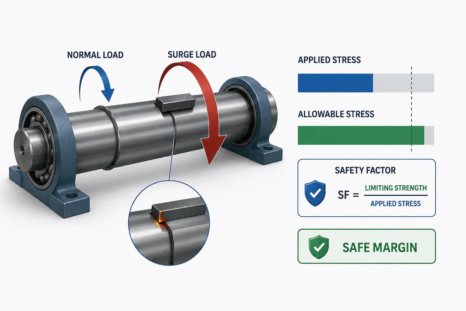
A safety factor is a numerical ratio used to compare the capacity or limiting strength of a component with the stress or load expected during service. It provides a margin between the calculated service demand and the relevant limiting condition.
A simplified expression is:
Where:
- SF = safety factor
- Limiting strength = relevant material or component strength
- Applied stress = calculated service stress
For example, if a component has a relevant limiting strength of 300 MPa and the calculated maximum service stress is 150 MPa:
SF = 300 / 150 = 2.0
This means the limiting strength is twice the calculated applied stress under the assessed condition.
The numerical value of a safety factor should not be selected arbitrarily. It depends on the component, loading condition, consequence of failure, uncertainty in loading, material behaviour, manufacturing quality, applicable design requirements and service environment.
Key Concepts in Safety-Factor and Stress Assessment
| Key concept | Definition | Engineering significance | Typical application |
|---|---|---|---|
| Applied stress | Stress generated by an operating load | Represents actual mechanical demand | Shaft, gear or pin assessment |
| Allowable stress | Maximum permitted design stress under specified conditions | Establishes an acceptable design limit | Critical mechanical components |
| Limiting strength | Strength associated with the relevant failure criterion | Provides a basis for comparison | Yield or ultimate strength |
| Safety factor | Ratio between limiting capacity and applied demand | Provides design margin | Surge and overload assessment |
| Yield strength | Stress associated with the onset of significant plastic deformation | Important for permanent deformation assessment | Shafts, brackets and gears |
| Ultimate tensile strength | Maximum tensile stress before tensile failure | Helps assess fracture margin | Tensile-loaded components |
| Stress concentration | Local increase in stress caused by geometry or discontinuity | Can significantly increase local stress | Keyways, holes and shoulders |
| Dynamic load | Load varying with time or motion | May exceed static loading | Rotating machinery |
| Surge load | Temporary increase above normal operating load | Tests transient component capacity | Drive systems and pumps |
| Fatigue | Progressive damage from repeated cyclic loading | Important for moving components | Shafts, gears and rotating parts |
| Allowable limit | Defined boundary for acceptable service performance | Supports acceptance decisions | QA/QC verification |
Identifying Critical Moving Parts
Not every component requires the same depth of stress assessment. Critical moving parts deserve particular attention because their failure can cause equipment damage, loss of containment, production interruption or secondary hazards.
Examples include:
Drive shafts.
Gear shafts.
Rotating couplings.
Gears.
Sprockets.
Flywheels.
Impellers.
Rotors.
Connecting rods.
Crankshafts.
Pins.
Bearings and bearing supports.
High-load fasteners.
Rotating hubs.
Mechanical drive components.
Hydraulic actuator components.
Moving linkages.
A component should be considered critical where its failure could have significant consequences or where it operates under high cyclic, dynamic or transient loading.
Establishing the Normal Operating Load
Before calculating a safety factor, the normal operating condition must be clearly established. The calculated stress is only meaningful if the applied load is representative of the actual service requirement.
Relevant information may include:
Normal operating torque.
Normal rotational speed.
Operating pressure.
Component weight.
External mechanical loads.
Axial loads.
Radial loads.
Bending loads.
Torsional loads.
Operating temperature.
Duty cycle.
Start-up conditions.
Shutdown conditions.
Acceleration and deceleration.
Expected load fluctuations.
Operating data should preferably be supported by reliable engineering documentation, equipment specifications, test data or measured operating information.
Identifying Sudden Operational Surges
A critical part of the assessment is determining what may cause a temporary increase in loading.
Sudden operational surges can result from:
Rapid acceleration.
Emergency stopping.
Sudden changes in process load.
Motor starting conditions.
Torque fluctuations.
Pump pressure surges.
Sudden valve operation.
Mechanical jamming.
Impact loading.
Misalignment.
Sudden changes in rotational speed.
Drive-system instability.
Unexpected resistance.
Process interruptions.
The maximum foreseeable transient load should be identified where the design assessment requires it. Using only the average operating load can produce an unrealistic assessment of component integrity.
Static and Dynamic Loading
Static loading is relatively constant or changes slowly enough that dynamic effects are insignificant for the assessment. Dynamic loading changes with time and may introduce additional forces or stresses.
Moving components frequently experience dynamic loading because acceleration, deceleration, rotation and cyclic movement are inherent to their operation.
Dynamic effects may involve:
Inertial forces.
Centrifugal effects.
Impact forces.
Torque fluctuations.
Vibratory stresses.
Resonance.
Repeated loading.
Transient acceleration.
For this reason, a component that appears adequate under a static calculation may require further evaluation under dynamic operating conditions.
Calculating Basic Mechanical Stress
The type of stress calculation depends on how the component is loaded.
Common forms include:
Tensile stress.
Compressive stress.
Shear stress.
Bending stress.
Torsional stress.
Combined stress.
For a simple axial load:
σ = F / A
Where:
- σ = normal stress
- F = applied force
- A = cross-sectional area
For a simple torque-driven shaft, torsional stress is related to the applied torque, shaft geometry and polar section properties. The exact equation depends on the shaft geometry and engineering model used.
The important QA/QC principle is that the calculated stress must represent the actual critical loading condition and not merely the easiest load to calculate.
Bending Stress in Moving Components
Shafts and rotating members may experience bending because of externally applied forces, gear forces, belt loads, bearing reactions or misalignment.
A simplified bending relationship is:
σ_b = M × c / I
Where:
- σ_b = bending stress
- M = bending moment
- c = distance from the neutral axis
- I = second moment of area
The calculation demonstrates why geometry is important. Increasing the effective section size can substantially influence bending resistance.
When assessing a shaft, the engineer should consider:
Shaft diameter.
Bending moment.
Torque.
Bearing locations.
Gear locations.
Keyways.
Shoulders.
Fillets.
Surface condition.
Material properties.
Torsional Stress in Shafts
Torque is particularly important for shafts, couplings and rotating drive components. A sudden increase in torque can cause a corresponding increase in torsional stress.
For example, a drive shaft normally transmitting 1,000 N·m may experience a transient torque of 1,500 N·m during a sudden operational event. The stress assessment should consider the transient torque rather than relying solely on the normal operating torque if that surge is reasonably foreseeable.
The assessment should also consider:
Shaft diameter.
Shaft material.
Keyways.
Splines.
Couplings.
Stress concentrations.
Torsional vibration.
Repeated torque cycles.
Combined Stress Conditions
Critical moving components often experience more than one type of stress at the same time. A shaft may simultaneously experience:
Bending from external loads.
Torsion from transmitted torque.
Axial loading.
Cyclic stress from rotation.
Thermal effects.
It is therefore important to assess the combined loading condition rather than considering each stress independently where interaction is significant.
The engineering assessment should identify the governing stress condition and compare it with the applicable allowable criterion.
Stress Concentration
One of the most important considerations in mechanical component assessment is the presence of local geometric features that increase stress.
Common stress concentration locations include:
Keyways.
Sharp shoulders.
Holes.
Grooves.
Threads.
Splines.
Abrupt diameter changes.
Weld toes.
Machining marks.
Surface defects.
A nominal stress calculation based on a smooth, uniform component may underestimate the actual local stress.
For this reason, the assessment may require a stress concentration factor or another appropriate engineering method.
Example of Stress Concentration
Consider a rotating shaft with a keyway. The nominal torsional stress may appear comfortably below the material’s allowable value. However, the keyway interrupts the shaft geometry and creates a local concentration of stress.
The QA/QC assessment should therefore consider:
Nominal shaft stress.
Keyway geometry.
Material condition.
Surface finish.
Cyclic loading.
Stress concentration.
Fatigue sensitivity.
Ignoring the keyway could produce an overly optimistic safety assessment.
Selecting an Appropriate Safety Factor
The safety factor should reflect the level of uncertainty and consequence associated with the component.
Relevant considerations include:
Consequence of failure.
Accuracy of load calculations.
Reliability of material properties.
Manufacturing variability.
Loading uncertainty.
Dynamic effects.
Fatigue exposure.
Operating environment.
Inspection capability.
Failure detectability.
Applicable design requirements.
Importance of the component.
A high-consequence component may require a more conservative design approach than a non-critical component, but the actual value must be established according to the applicable engineering design basis rather than chosen simply because a larger number appears safer.
Allowable Stress and Stress Limits
An allowable stress represents a defined upper limit against which calculated service stress can be evaluated.
A simplified relationship can be expressed as:
σ_allowable = σ_limit / SF
Where:
- σ_allowable = allowable stress
- σ_limit = relevant limiting strength
- SF = selected safety factor
For example:
σ_allowable = 360 MPa / 2 = 180 MPa
A calculated stress of 150 MPa would therefore be below this simplified allowable value.
However, real engineering assessments may involve more complex criteria, including temperature-dependent properties, fatigue limits, buckling, fracture mechanics, code-specific allowable stresses and combined loading. The simplified calculation should therefore be treated as an educational illustration rather than a substitute for the applicable design methodology.
Safety Factors Under Sudden Operational Surges
Sudden surges are particularly important because the component may experience a load significantly above its normal operating level.
A practical assessment sequence is:
Establish the normal operating load.
Identify foreseeable surge conditions.
Determine the peak transient load.
Calculate the corresponding stress.
Consider dynamic effects.
Identify stress concentrations.
Establish the applicable material limit.
Apply the appropriate safety factor.
Compare calculated stress with allowable stress.
Determine whether the component has adequate margin.
The critical point is that the safety factor should be applied consistently to the correct design condition.
Example: Rotating Drive Shaft
A drive shaft normally transmits 800 N·m of torque. During an identified operational surge, torque may temporarily reach 1,200 N·m.
If the shaft is assessed only against 800 N·m, the calculation may underestimate the maximum service stress. The engineer should assess the 1,200 N·m surge condition and determine whether the resulting stress remains within the applicable allowable limit.
The assessment should also consider:
Shaft diameter.
Material strength.
Keyway geometry.
Stress concentration.
Number of surge events.
Torsional fatigue.
Operating temperature.
Manufacturing quality.
This demonstrates why surge assessment is essential for rotating machinery.
Safety Factor and Fatigue
A safety factor based only on static strength may not fully address repeated loading. Moving components often experience thousands or millions of stress cycles.
Fatigue assessment should consider:
Stress amplitude.
Mean stress.
Number of cycles.
Surface finish.
Material condition.
Stress concentration.
Operating speed.
Load spectrum.
Previous fatigue damage.
Environmental effects.
A component can therefore have a satisfactory static safety factor while still requiring fatigue assessment because repeated loading may initiate progressive cracking.
Dynamic Effects and Vibration
Vibration can significantly influence moving component integrity. Excessive vibration may create additional cyclic stresses, increase bearing loads, promote fatigue and indicate imbalance, misalignment or other mechanical problems.
A QA/QC assessment should consider whether:
Operating speed creates significant vibration.
The component passes through critical speed ranges.
Rotating masses are balanced.
Shaft alignment is acceptable.
Bearings are functioning correctly.
Dynamic loads exceed assumptions.
Vibration trends are increasing.
An increasing vibration trend can be an early indication that the original stress assumptions no longer represent actual operating behaviour.
Temperature Effects on Stress Limits
Material strength can vary with temperature. Therefore, a stress limit established at ambient temperature should not automatically be applied to a component operating at substantially higher temperatures.
The assessment should consider:
Material strength at service temperature.
Thermal expansion.
Temperature gradients.
Thermal cycling.
Creep where relevant.
Lubrication effects.
Changes in material behaviour.
For components exposed to severe temperature conditions, the applicable temperature-dependent design requirements should be used.
Material Properties and Safety-Factor Assessment
The reliability of a stress calculation depends partly on the quality of the material data used.
Relevant material information may include:
Yield strength.
Tensile strength.
Shear strength.
Fatigue properties.
Toughness.
Hardness.
Temperature-dependent strength.
Heat-treatment condition.
The QA/QC engineer should verify that the material being assessed corresponds to the actual component and that the relevant material condition has been correctly identified.
Material certificates, inspection records and testing results can support this verification.
Process for Calculating Safety Factors
Stage 1: Define the Component
Identify:
Component type.
Material.
Geometry.
Function.
Critical sections.
Connection details.
Stage 2: Establish Loading Conditions
Determine:
Normal load.
Maximum operating load.
Transient load.
Cyclic load.
Impact load.
Thermal load.
Stage 3: Calculate Stresses
Determine relevant:
Tensile stress.
Bending stress.
Shear stress.
Torsional stress.
Combined stress.
Stage 4: Identify Local Stress Effects
Review:
Keyways.
Grooves.
Threads.
Holes.
Shoulders.
Welded regions.
Surface defects.
Stage 5: Establish Material Limits
Confirm:
Relevant strength.
Service temperature.
Material condition.
Applicable allowable limit.
Stage 6: Apply the Safety Factor
Use the applicable engineering design methodology to establish the required margin.
Stage 7: Compare Demand and Capacity
Determine whether:
Calculated stress is below allowable stress.
Surge conditions remain acceptable.
Fatigue considerations are satisfactory.
Local stress concentrations remain controlled.
Stage 8: Document the Decision
Record:
Assumptions.
Loads.
Calculations.
Material data.
Safety factor.
Stress limits.
Inspection evidence.
Final engineering decision.
Practical QA/QC Checklist for Stress Assessment
When reviewing a critical moving component, the QA/QC professional should verify that the assessment addresses:
Component identification.
Material specification.
Material traceability.
Geometry.
Normal operating load.
Maximum foreseeable load.
Surge conditions.
Dynamic loading.
Stress concentrations.
Temperature.
Cyclic loading.
Fatigue risk.
Inspection condition.
Manufacturing quality.
Applicable acceptance criteria.
Calculated stress.
Allowable stress.
Safety factor.
Engineering approval.
Practical Example: Gear and Shaft Assembly
Consider a gearbox used to drive heavy industrial equipment. The shaft normally transmits a steady torque, but the machine occasionally experiences sudden resistance when the driven equipment encounters a temporary process obstruction.
The original design calculation considered normal torque but did not adequately document the transient condition.
A revised QA/QC assessment should:
Establish normal torque.
Determine the foreseeable surge torque.
Calculate shaft torsional stress.
Assess bending caused by gear forces.
Review keyway stress concentration.
Check material properties.
Consider fatigue from repeated surge events.
Review shaft inspection history.
Determine whether the existing stress margin remains acceptable.
If the calculated peak stress approaches or exceeds the applicable allowable limit, potential engineering actions could include reducing the surge load, modifying operating controls, improving component geometry, selecting a suitable material, increasing shaft dimensions or implementing another technically justified control.
Practical Example: Pump Shaft During Sudden Start-Up
A pump shaft experiences rapid acceleration during start-up. The normal operating condition is stable, but start-up creates a temporary increase in torque.
The assessment should distinguish between:
Steady-state torque.
Start-up torque.
Acceleration torque.
Potential pressure-related loading.
Repeated start-stop cycles.
If the pump starts frequently, the transient event may become a significant fatigue consideration even if the individual surge does not exceed the static strength limit.
The QA/QC assessment therefore needs to consider both peak stress and the number of repeated cycles.
Practical Example: Connecting Pin Under Impact Loading
A mechanical linkage contains a high-strength connecting pin. During normal movement, the pin experiences moderate shear and bending. However, sudden stopping creates impact loading.
The assessment should consider:
Normal load.
Peak impact load.
Pin diameter.
Shear stress.
Bending stress.
Contact stress.
Material strength.
Surface condition.
Wear.
Stress concentration.
A simple calculation based only on the normal load could underestimate the actual service demand.
Case Study: Sudden Operational Surge in a Critical Rotating Assembly
Background
A heavy industrial machine uses a rotating shaft to transmit mechanical power between a drive motor and a production unit. Under normal conditions, the shaft operates within its established torque range. However, production records show occasional sudden load increases when material enters the downstream equipment unevenly.
Operators report that the machine occasionally experiences a brief increase in vibration during these events.
Initial QA/QC Concern
The shaft has passed its original dimensional and material verification checks. Its material certificate is compliant, and routine inspection has not identified visible damage.
However, the combination of:
Torque surges.
Increased vibration.
Repeated operation.
Stress concentration at a keyway.
Cyclic loading.
creates a potential reliability concern.
Assessment
The engineering team first establishes the normal torque and peak observed torque. The stress calculation is then performed for both normal and transient conditions.
The assessment also reviews:
Shaft material.
Shaft diameter.
Keyway dimensions.
Surface condition.
Alignment.
Bearing condition.
Historical vibration.
Number of surge events.
Previous inspection findings.
The calculated stress under normal conditions is comfortably below the applicable allowable limit. However, the transient condition produces significantly higher stress.
Engineering Interpretation
The result demonstrates that normal operating stress alone does not adequately represent the component’s service demand. The transient load must be considered because it is a foreseeable operating event.
The repeated nature of the surge also means that fatigue should be considered. The keyway becomes particularly important because it creates a local stress concentration.
Corrective Considerations
Depending on the engineering assessment, potential controls could include:
Reducing the magnitude of load surges.
Improving process control.
Investigating alignment.
Monitoring vibration.
Reviewing keyway geometry.
Increasing inspection frequency.
Assessing fatigue life.
Reviewing shaft design.
Replacing or modifying the component where required.
Case Study Conclusion
The case demonstrates that component safety cannot be established solely by comparing normal operating stress with material strength. A reliable assessment must consider transient loads, dynamic effects, stress concentration and repeated loading. The combination of calculation and operational evidence provides a stronger basis for determining whether the component remains suitable for service.
Common Errors in Safety-Factor Calculations
Poor stress assessments can result from incorrect assumptions, incomplete operating data or inappropriate application of safety factors.
Common errors include:
Using normal load instead of maximum foreseeable load.
Ignoring transient operational surges.
Treating dynamic loads as static loads.
Ignoring stress concentrations.
Using outdated material properties.
Applying room-temperature properties at elevated temperature.
Ignoring fatigue.
Ignoring repeated start-stop cycles.
Assuming a larger safety factor automatically resolves every uncertainty.
Failing to verify component dimensions.
Ignoring manufacturing defects.
Ignoring surface condition.
Failing to document assumptions.
Using inappropriate acceptance limits.
Treating a simplified calculation as a complete design assessment.
Benefits of Appropriate Safety-Factor Assessment
A properly structured safety-factor assessment provides significant engineering and operational benefits.
Improves mechanical reliability.
Reduces unexpected component failure.
Identifies inadequate stress margins.
Supports safe equipment operation.
Helps control transient loading risks.
Supports maintenance planning.
Identifies fatigue-sensitive components.
Improves inspection priorities.
Supports material-selection decisions.
Provides evidence for design verification.
Helps evaluate engineering modifications.
Reduces unplanned downtime.
Protects critical machinery.
Strengthens QA/QC documentation.
Supports evidence-based professional judgement.
Using Inspection Data to Validate Stress Assumptions
Calculated stress should not always be considered independently from actual component condition. Inspection data can provide valuable evidence about whether the component is behaving as expected.
Useful information includes:
Crack indications.
Surface damage.
Wear patterns.
Shaft runout.
Vibration measurements.
Bearing condition.
Dimensional changes.
Deformation.
Previous repairs.
Fatigue indications.
Operating temperature.
If inspection results reveal deterioration despite an apparently adequate calculated safety factor, the engineering assessment should investigate whether the original assumptions remain valid.
Linking Safety Factors with Continuous Improvement
Safety-factor assessment can also contribute to continuous improvement. When repeated surge events or component failures are identified, the organisation can analyse the underlying causes rather than simply replacing failed parts.
Potential improvement actions include:
Improving operating procedures.
Reducing unnecessary load fluctuations.
Improving alignment.
Optimising component geometry.
Improving material selection.
Improving lubrication.
Increasing monitoring.
Revising inspection intervals.
Updating design assumptions.
Reviewing previous failure data.
This approach changes QA/QC from a purely inspection-based function into a proactive reliability-management activity.
Professional Decision-Making Framework
When determining whether a critical moving part can safely withstand sudden operational surges, the following decision sequence provides a practical framework:
Identify
Identify the component, function, material and critical loading locations.
Quantify
Quantify normal, maximum and foreseeable transient loads.
Calculate
Calculate the relevant stresses under the governing loading conditions.
Correct
Account for geometry, stress concentrations, dynamic effects and other relevant factors.
Compare
Compare calculated stresses against the applicable allowable limits.
Evaluate
Consider fatigue, temperature, material condition, manufacturing quality and inspection evidence.
Decide
Determine whether the component has adequate margin for the intended service.
Document
Record calculations, assumptions, evidence, acceptance criteria and engineering conclusions.
Final Engineering Perspective
Safety factors and stress limits are fundamental tools for assessing the reliability of critical mechanical components, particularly those subjected to sudden operational surges. However, the safety factor should never be treated as an arbitrary number that automatically guarantees component integrity. Its value depends on the quality of the underlying load information, material data, component geometry, failure mechanism, manufacturing condition and applicable engineering design requirements.
A robust assessment begins with the actual operating envelope and includes foreseeable transient conditions. Normal torque, pressure or mechanical loading should be supplemented by credible surge conditions, dynamic effects and cyclic behaviour. Stress concentrations at keyways, grooves, shoulders, holes and other geometric discontinuities must also be considered because local stresses can be substantially higher than nominal calculated values.
Conclusion
Calculating safety factors and stress limits enables mechanical engineering and QA/QC professionals to establish whether critical moving components possess sufficient capacity to withstand normal operation and foreseeable sudden operational surges. The assessment requires accurate identification of loads, appropriate stress calculations, reliable material data, consideration of geometry and stress concentration, and comparison against applicable allowable limits. For rotating and moving components, fatigue, vibration, dynamic loading and repeated transient events must also be considered because a component can remain below its static strength limit while still accumulating progressive damage.
The most reliable approach is therefore evidence-based and risk-focused. Engineers should combine calculations with material records, manufacturing information, inspection results, operating history and observed equipment behaviour. When these factors are evaluated together, safety factors become a practical tool for controlling mechanical failure risk, improving component reliability and supporting defensible QA/QC decisions. Where calculated margins are inadequate or operating conditions have changed, appropriate engineering controls should be introduced before component integrity is compromised.
3: Validate the Suitability of Specific Valves, Pipes, or Rotating Parts by Matching Their Performance Data Sheets Against Actual Plant Operating Limits
Mechanical equipment such as valves, pipes, pumps, compressors, shafts, couplings and other rotating components must be demonstrably suitable for the conditions in which they will actually operate. A component may appear technically acceptable based on its catalogue description, material certificate or nominal design rating, yet still be unsuitable for a particular plant if its pressure, temperature, flow, speed, torque, chemical compatibility, vibration or other performance limits are exceeded. Effective mechanical QA/QC therefore requires a systematic comparison between documented equipment performance data and the real operating envelope of the plant.
Validating equipment suitability is fundamentally an evidence-based engineering activity. The performance data sheet establishes what the manufacturer or designer states the component can achieve under defined conditions, while plant operating information establishes what the equipment will actually experience. The QA/QC professional must bring these two sources of information together, identify differences, evaluate margins, and determine whether the component can safely and reliably perform its intended function.
This approach is particularly important for pressure-containing equipment, process piping, control valves, isolation valves, pumps, compressors and rotating machinery because their failure can affect production, containment, equipment integrity and personnel safety. The assessment should therefore consider both normal operating conditions and reasonably foreseeable variations, including start-up, shutdown, pressure surges, temperature excursions, changes in flow, transient loads and other abnormal but credible operating conditions.
Purpose of Performance Data Sheet Validation
A performance data sheet contains technical information that defines the expected operating capability of a component. Depending on the equipment, it may include pressure ratings, temperature limits, flow capacity, differential pressure, rotational speed, power requirements, torque, materials, dimensions, efficiency, vibration limits and other technical parameters.
The purpose of validation is to determine whether those documented capabilities are compatible with actual plant requirements.
The assessment should answer questions such as:
- Can the valve withstand the actual plant pressure?
- Is the valve material compatible with the process fluid?
- Is the pipe suitable for the operating and design temperature?
- Can the pipe withstand pressure and mechanical loading?
- Can a pump deliver the required flow and pressure?
- Is the pump operating point within its acceptable performance range?
- Can a rotating shaft withstand the operating torque and speed?
- Is the equipment suitable for start-up and shutdown conditions?
- Is there sufficient engineering margin?
- Are actual operating conditions within the manufacturer’s stated limits?
- Has the equipment been selected for the actual service environment?
A positive answer should be supported by documented evidence rather than assumptions.
Understanding the Plant Operating Envelope
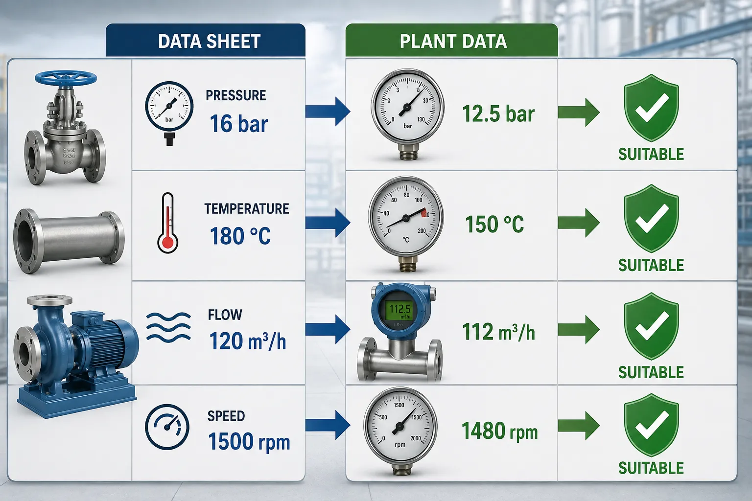
The plant operating envelope describes the range of conditions under which equipment is expected to operate. It normally includes both routine operating conditions and defined limits.
Relevant parameters can include:
- Normal operating pressure.
- Maximum operating pressure.
- Minimum operating pressure.
- Design pressure.
- Normal temperature.
- Maximum temperature.
- Minimum temperature.
- Flow rate.
- Differential pressure.
- Fluid density.
- Fluid viscosity.
- Chemical composition.
- Rotational speed.
- Torque.
- Power.
- Vibration.
- Mechanical loading.
- Start-up conditions.
- Shutdown conditions.
- Pressure surges.
- Temperature excursions.
- Operating cycles.
The difference between normal operating values and maximum allowable values is particularly important. A component may be acceptable during normal operation but become unsuitable during a foreseeable transient condition.
Key Concepts for Equipment Suitability Validation
| Key concept | Definition | Importance in validation | Example evidence |
|---|---|---|---|
| Performance data sheet | Document defining equipment performance characteristics and limits | Establishes documented equipment capability | Manufacturer data sheet |
| Operating limit | Maximum or minimum acceptable operating condition | Defines the permissible service envelope | Equipment specification |
| Design pressure | Pressure used as a basis for equipment design | Establishes pressure-resistance requirements | Design documentation |
| Operating pressure | Actual pressure experienced during service | Shows real mechanical demand | Plant operating records |
| Design temperature | Temperature considered during design | Establishes thermal requirements | Engineering specification |
| Operating temperature | Actual service temperature | Confirms thermal compatibility | Process records |
| Flow rate | Volume or mass of fluid passing through equipment | Important for valves, pumps and pipes | Flow measurements |
| Differential pressure | Pressure difference across equipment | Critical for valve and pump performance | Pressure records |
| Pressure rating | Maximum pressure associated with defined conditions | Supports pressure suitability assessment | Manufacturer documentation |
| Material compatibility | Ability of material to withstand service environment | Controls corrosion and degradation risk | Material specification |
| Rotational speed | Operating speed of rotating equipment | Influences mechanical and dynamic stresses | Equipment data sheet |
| Torque rating | Maximum specified torque capacity | Important for shafts, couplings and actuators | Manufacturer data |
| Safety margin | Difference between operating demand and permitted limit | Indicates available operating reserve | Engineering calculation |
Types of Equipment Requiring Validation
The principle applies to many mechanical components and equipment types.
Valves
Valve suitability may depend on:
- Pressure rating.
- Temperature rating.
- Flow capacity.
- Differential pressure.
- Valve size.
- Material.
- Trim material.
- Sealing system.
- Actuator capability.
- Operating torque.
- Chemical compatibility.
- Pressure drop.
- Operating frequency.
Pipes
Pipe validation may consider:
- Nominal size.
- Wall thickness.
- Material grade.
- Pressure capability.
- Temperature range.
- Corrosion allowance.
- Fluid compatibility.
- Flow requirements.
- External loading.
- Support arrangement.
- Thermal expansion.
- Connection type.
Pumps
Pump suitability may require evaluation of:
- Flow rate.
- Head.
- Differential pressure.
- Speed.
- Power.
- Efficiency.
- Fluid properties.
- Temperature.
- Net positive suction conditions where applicable.
- Vibration.
- Operating range.
Rotating Components
Rotating parts may include:
- Shafts.
- Couplings.
- Impellers.
- Rotors.
- Gears.
- Flywheels.
- Drive components.
Relevant parameters include:
- Maximum speed.
- Torque.
- Power.
- Shaft strength.
- Dynamic loading.
- Balance.
- Vibration.
- Temperature.
- Fatigue exposure.
Reading a Valve Performance Data Sheet
A valve data sheet provides information necessary to determine whether the valve is appropriate for the service.
Important information may include:
- Valve type.
- Nominal size.
- Pressure class or rating.
- Design pressure.
- Design temperature.
- Body material.
- Trim material.
- Seal material.
- Flow coefficient.
- Maximum differential pressure.
- Actuator requirements.
- Operating torque.
- Leakage classification where specified.
- Process fluid.
- Installation requirements.
The QA/QC engineer should compare each relevant parameter with the plant requirement.
For example, if a valve is rated for a particular pressure and temperature range but the plant operates above one of those limits, the valve cannot simply be accepted because its nominal size and material appear correct.
Valve Pressure Validation
Pressure is one of the first parameters to verify.
The assessment should compare:
- Plant normal pressure.
- Plant maximum operating pressure.
- Plant design pressure.
- Valve rated pressure.
- Pressure surges.
- Differential pressure across the valve.
A simple comparison can be expressed as:
Valve Pressure Rating >= Maximum Applicable Plant Pressure
However, this comparison should be interpreted according to the applicable equipment specification and rating conditions. Pressure ratings may depend on temperature, material and equipment configuration.
Practical Valve Example
Suppose a plant line normally operates at 8 MPa, while a foreseeable transient can reach 9 MPa. A valve data sheet indicates a rated pressure of 10 MPa under the applicable conditions.
The assessment should not compare only 8 MPa with 10 MPa. The 9 MPa transient should also be considered because it represents a foreseeable operating demand.
The simplified pressure margin is:
Pressure Margin = Valve Rating – Maximum Applicable Pressure
Pressure Margin = 10 MPa – 9 MPa = 1 MPa
This provides a simplified indication of the available pressure margin, although the formal engineering acceptance must consider the applicable rating basis, temperature and other requirements.
Temperature Validation for Valves and Pipes
Temperature can significantly influence equipment performance and material strength. A valve body, gasket, seal, pipe or rotating component may have different allowable limits depending on temperature.
The QA/QC assessment should compare:
- Minimum design temperature.
- Maximum design temperature.
- Normal operating temperature.
- Maximum operating temperature.
- Start-up temperature.
- Shutdown temperature.
- Thermal cycling.
- Material limitations.
The evaluation should also consider whether seals, gaskets and other non-metallic components remain suitable.
Practical Example
A pipe system normally operates at 180°C but may reach 210°C during a controlled process excursion. The pipe material and associated components must be assessed against the highest credible temperature rather than the normal 180°C alone.
The QA/QC professional should verify:
- Material suitability.
- Pressure-temperature relationship.
- Gasket suitability.
- Thermal expansion.
- Support arrangement.
- Insulation requirements.
- Historical temperature excursions.
Validating Pipe Suitability
Pipe suitability involves more than confirming nominal diameter. The pipe must be able to withstand pressure, temperature, mechanical loading and environmental conditions while providing the required flow capacity.
The assessment should include:
- Pipe size.
- Material grade.
- Wall thickness.
- Design pressure.
- Operating pressure.
- Design temperature.
- Operating temperature.
- Corrosion allowance.
- Chemical compatibility.
- Flow requirement.
- External mechanical loading.
- Thermal expansion.
Wall Thickness Considerations
A pipe may have the correct nominal specification but experience wall loss during service. Historical thickness measurements should therefore be considered when validating continued suitability.
Relevant evidence includes:
- Original wall thickness.
- Minimum measured wall thickness.
- Historical thickness measurements.
- Corrosion rate.
- Design requirements.
- Inspection interval.
- Remaining service margin.
The assessment should focus on current and projected condition rather than relying solely on the original specification.
Flow and Pressure Drop
For valves and pipes, flow performance is another important consideration. A component may withstand pressure but still be unsuitable if it restricts flow excessively or cannot deliver the required process capacity.
The assessment should consider:
- Required flow.
- Actual flow.
- Pressure drop.
- Valve opening position.
- Pipe diameter.
- Fluid properties.
- Flow velocity.
- Pump capacity.
For a control valve, operating close to a fully open or fully closed condition may indicate that the selected valve is not operating within an appropriate control range.
Validating Pump Performance
Pump performance data typically relate flow, head, pressure, speed, efficiency and power. The actual plant operating point should be compared with the manufacturer’s documented performance.
A simplified assessment should identify:
- Required flow.
- Required head.
- Actual flow.
- Actual head.
- Pump speed.
- Motor power.
- Fluid temperature.
- Fluid density.
- Fluid viscosity.
- Operating range.
- Vibration.
Practical Pump Example
A process requires a flow of 200 m³/h at a specified head. The selected pump data sheet indicates a performance range that includes this operating point.
During commissioning, actual measurements show the pump operating substantially outside the expected point.
The QA/QC response should investigate:
- Actual suction pressure.
- Discharge pressure.
- Flow measurement.
- Pump speed.
- Valve position.
- Fluid properties.
- System resistance.
- Pump condition.
The pump should not be accepted simply because the catalogue data sheet appears suitable. Actual plant performance must correspond with the intended operating requirement.
Rotating Equipment Validation
Rotating components can experience significant mechanical and dynamic stresses. The assessment should compare actual operating speed and torque with component ratings.
Important parameters include:
- Maximum continuous speed.
- Maximum transient speed.
- Operating torque.
- Peak torque.
- Power.
- Shaft dimensions.
- Material.
- Balance requirements.
- Vibration limits.
- Bearing loads.
- Temperature.
A rotating shaft operating at a speed significantly higher than its validated operating range may experience increased dynamic stresses and vibration.
Matching Actual Data with Manufacturer Data
The validation process should use a structured comparison matrix.
For example:
| Parameter | Manufacturer/Data Sheet | Actual Plant Condition | Assessment |
|---|---|---|---|
| Pressure | 10 MPa maximum | 8.5 MPa normal | Within limit |
| Temperature | 250°C maximum | 220°C maximum | Within limit |
| Flow | 150–250 m³/h | 200 m³/h | Within range |
| Speed | 3,000 rpm maximum | 2,800 rpm | Within limit |
| Torque | 1,500 N·m maximum | 1,200 N·m peak | Within limit |
| Chemical service | Specified fluid | Actual process fluid | Verify compatibility |
| Vibration | Manufacturer limit | Measured plant value | Compare and trend |
This type of matrix makes discrepancies easier to identify and provides a clear QA/QC record.
Establishing Acceptance Criteria
Acceptance criteria should be established before making the final suitability decision.
Criteria may relate to:
- Pressure.
- Temperature.
- Flow.
- Speed.
- Torque.
- Material.
- Chemical compatibility.
- Vibration.
- Dimensional requirements.
- Leakage.
- Performance efficiency.
A simple decision structure can be:
Actual Condition <= Applicable Equipment Limit → Potentially acceptable
Actual Condition > Applicable Equipment Limit → Requires engineering review
However, the assessment should also consider whether the equipment is operating too close to its limit to provide a suitable margin.
Considering Operating Margin
Operating margin is important because operating exactly at a maximum rating leaves little reserve for uncertainty or transient events.
For example:
Operating Margin = Applicable Limit – Maximum Expected Operating Condition
If a component has a pressure limit of 12 MPa and maximum expected plant pressure is 10 MPa:
Operating Margin = 12 MPa – 10 MPa = 2 MPa
This does not automatically establish safe operation because the formal assessment must consider the applicable rating basis, pressure-temperature relationship, transients and other technical requirements. Nevertheless, the concept helps demonstrate why margin matters.
Procedure for Validating Equipment Suitability
Step 1: Identify the Equipment
Record:
- Equipment tag number.
- Manufacturer.
- Model.
- Size.
- Material.
- Serial number.
- Revision status.
Step 2: Collect Performance Documentation
Obtain:
- Manufacturer data sheet.
- Technical specification.
- Design documentation.
- Material certificates.
- Test records.
- Inspection records.
- Operating manual.
- Approved drawings.
Step 3: Establish Actual Plant Conditions
Collect:
- Pressure data.
- Temperature data.
- Flow data.
- Speed data.
- Torque data.
- Chemical information.
- Vibration data.
- Operating cycles.
Step 4: Identify Maximum and Minimum Conditions
Do not rely solely on average operating values.
Determine:
- Maximum pressure.
- Minimum pressure.
- Maximum temperature.
- Minimum temperature.
- Maximum flow.
- Minimum flow.
- Maximum speed.
- Maximum torque.
- Transient conditions.
Step 5: Compare Data
Create a parameter-by-parameter comparison.
Check:
- Rating.
- Material.
- Capacity.
- Pressure.
- Temperature.
- Speed.
- Torque.
- Chemical compatibility.
Step 6: Identify Discrepancies
Record any:
- Exceeded limits.
- Missing information.
- Unverified assumptions.
- Conflicting documentation.
- Unexpected operating conditions.
Step 7: Assess the Engineering Significance
Determine whether the discrepancy affects:
- Safety.
- Integrity.
- Reliability.
- Performance.
- Service life.
- Quality.
Step 8: Obtain Additional Evidence Where Required
Possible evidence may include:
- Additional inspection.
- Performance testing.
- Material verification.
- Vibration measurement.
- Pressure testing.
- Engineering calculation.
- Manufacturer confirmation.
Step 9: Make the Suitability Decision
Possible decisions include:
- Accept.
- Accept with defined controls.
- Require additional assessment.
- Repair.
- Modify.
- Replace.
- Reject.
Step 10: Document the Decision
The final record should identify:
- Equipment.
- Operating conditions.
- Applicable limits.
- Evidence reviewed.
- Deviations.
- Engineering assessment.
- Final decision.
- Approval.
Validating Chemical Compatibility
Chemical compatibility is particularly important for valves, pipes and pumps handling aggressive process fluids.
The assessment should consider:
- Chemical identity.
- Concentration.
- Temperature.
- Pressure.
- Flow velocity.
- Contaminants.
- Moisture.
- Exposure duration.
Material compatibility should be verified against appropriate technical information. A component that is suitable for one concentration or temperature may not necessarily be suitable under another combination of conditions.
Potential degradation mechanisms include:
- General corrosion.
- Pitting.
- Crevice corrosion.
- Erosion-corrosion.
- Stress-corrosion cracking.
- Chemical attack.
- Material embrittlement.
Considering Start-Up and Shutdown Conditions
Many equipment failures occur during transient conditions rather than steady-state operation.
Start-up and shutdown can create:
- Rapid pressure changes.
- Rapid temperature changes.
- Thermal expansion.
- Thermal contraction.
- Sudden flow changes.
- Torque fluctuations.
- Vibration.
- Differential pressure changes.
Therefore, validation should consider the complete operating cycle.
Practical Example: Valve Selection for a Process Line
A process line requires a valve to operate with a normal pressure of 6 MPa and a maximum foreseeable pressure of 8 MPa. The process temperature normally remains around 160°C but may temporarily reach 190°C.
The selected valve data sheet must be reviewed for:
- Pressure capability at the applicable temperature.
- Body material.
- Trim compatibility.
- Seal temperature capability.
- Differential pressure.
- Flow requirement.
- Actuator torque.
The QA/QC engineer should not simply compare 8 MPa with the valve’s headline pressure rating. The pressure-temperature relationship and actual service conditions must be considered.
Practical Example: Pipe for High-Temperature Chemical Service
A process pipe carries an aggressive chemical at elevated temperature. The original pipe specification appears suitable based on nominal pressure and temperature.
However, operating data show that the chemical concentration is higher than originally expected.
The QA/QC review should therefore investigate:
- Material compatibility.
- Corrosion history.
- Wall-thickness measurements.
- Chemical concentration.
- Temperature history.
- Corrosion allowance.
- Inspection trends.
If historical measurements demonstrate accelerated wall loss, continued use may require additional engineering controls even though the original pipe specification was compliant.
Practical Example: Rotating Shaft
A rotating shaft is specified for a maximum operating speed of 2,500 rpm. Plant operating data show that the machine regularly reaches 2,450 rpm and occasionally exceeds this value during transient conditions.
The assessment should consider:
- Maximum actual speed.
- Shaft material.
- Shaft diameter.
- Balance.
- Vibration.
- Bearing condition.
- Transient speed.
- Fatigue.
- Manufacturer’s operating limits.
The small numerical difference between normal speed and maximum rating should not automatically be considered insignificant. The significance depends on the equipment design, transient duration, dynamic behaviour and applicable technical requirements.
Case Study: Integrated Equipment Suitability Assessment
Case Background
A chemical-processing facility plans to increase production throughput. The modification will increase process flow, operating temperature and pump loading. Existing valves, pipes and rotating equipment are proposed for continued use.
The QA/QC engineer is asked to validate whether the existing equipment remains suitable.
Data Collection
The team collects:
- Manufacturer performance data sheets.
- Equipment specifications.
- Material certificates.
- Historical operating records.
- Pressure measurements.
- Temperature measurements.
- Flow measurements.
- Pump performance data.
- Vibration records.
- Inspection reports.
- Previous maintenance records.
Assessment of Valves
The valve data sheets are compared with the revised pressure, temperature and flow conditions. One valve remains within its documented pressure and temperature range, but its differential pressure approaches the upper operating limit.
The engineering team identifies this as an item requiring closer review rather than automatically accepting it.
Assessment of Pipes
The revised flow increases velocity. Historical thickness data show gradual corrosion. The team therefore evaluates whether increased flow velocity could influence erosion-corrosion and whether sufficient wall thickness remains available.
Assessment of Rotating Equipment
The pump must operate at a higher flow rate. The revised operating point is compared with the manufacturer’s performance curve and power requirements. Vibration data are also reviewed.
Engineering Decision
The review identifies that some components remain suitable while others require further evaluation or modification.
This demonstrates an important QA/QC principle: equipment suitability should be assessed individually against actual service requirements rather than assuming that an entire system remains acceptable because it operated successfully under previous conditions.
Common Validation Errors
Several weaknesses can undermine equipment suitability assessments.
Common errors include:
- Comparing only normal operating conditions.
- Ignoring transient conditions.
- Using outdated performance data sheets.
- Ignoring temperature effects on pressure ratings.
- Assuming catalogue values apply to every operating condition.
- Ignoring chemical compatibility.
- Ignoring flow requirements.
- Failing to review actual plant measurements.
- Ignoring equipment ageing.
- Ignoring historical inspection data.
- Accepting equipment based solely on material grade.
- Failing to assess operating margin.
- Ignoring vibration trends.
- Using average values instead of maximum credible conditions.
- Failing to document discrepancies.
Benefits of Performance Data Validation
A structured comparison between equipment data sheets and actual plant operating limits provides substantial benefits.
- Improves mechanical equipment reliability.
- Reduces unsuitable equipment installation.
- Identifies operating-limit exceedances.
- Supports safe equipment selection.
- Reduces premature equipment failure.
- Improves process performance.
- Supports maintenance planning.
- Helps control equipment ageing.
- Improves material compatibility decisions.
- Supports engineering change management.
- Provides objective QA/QC evidence.
- Improves technical documentation.
- Supports auditability.
- Helps prevent unplanned shutdowns.
- Strengthens engineering decision-making.
Using Digital Data for Validation
Modern plants can provide large quantities of operational data through monitoring and control systems. This data can improve equipment suitability assessment when it is accurate, traceable and correctly interpreted.
Useful data sources may include:
- Pressure transmitters.
- Temperature sensors.
- Flow meters.
- Speed sensors.
- Torque measurements.
- Vibration monitoring.
- Equipment historians.
- Maintenance management systems.
- Inspection databases.
The QA/QC professional should ensure that the data used for validation are relevant to the equipment being assessed and represent appropriate operating periods.
Managing Data Quality
Good engineering decisions depend on reliable data.
Data validation should consider:
- Measurement accuracy.
- Calibration status.
- Sampling frequency.
- Data completeness.
- Time period.
- Sensor location.
- Instrument reliability.
- Abnormal readings.
- Data gaps.
If plant records show a pressure value that conflicts significantly with another reliable measurement source, the discrepancy should be investigated before using the data as the basis for a critical suitability decision.
Change Management and Revalidation
Equipment suitability should be reassessed whenever significant plant changes occur.
Triggers may include:
- Increased production rate.
- Increased pressure.
- Increased temperature.
- Changed process chemical.
- Changed flow rate.
- Increased operating speed.
- Equipment modification.
- Material substitution.
- Process redesign.
- Changed operating cycle.
- Extended equipment service life.
This is particularly important because a component that was suitable for its original duty may not remain suitable after process changes.
Professional QA/QC Decision Framework
A practical decision framework can be summarised as:
Verify
Confirm the equipment identity and documentation.
Measure
Establish actual plant operating conditions.
Compare
Match actual conditions against documented equipment limits.
Evaluate
Assess margins, deviations and degradation mechanisms.
Validate
Obtain additional evidence where uncertainty exists.
Decide
Accept, modify, monitor, repair, replace or escalate as appropriate.
Record
Document the complete technical basis for the decision.
Final Professional Perspective
Validating valves, pipes and rotating parts against actual plant operating limits is an essential part of mechanical QA/QC because equipment performance cannot be separated from the environment in which the equipment operates. Manufacturer data sheets provide essential technical information, but they must be interpreted in relation to actual pressure, temperature, flow, speed, torque, chemical exposure and transient operating conditions.
The strongest validation process compares documented equipment capability with measured or reliably established plant conditions parameter by parameter. It also considers operating margins, ageing, inspection history, degradation mechanisms and foreseeable changes to plant operation. Where information is incomplete or conditions exceed documented limits, the appropriate response is controlled engineering review rather than assumption-based acceptance.
Conclusion
The suitability of mechanical valves, pipes and rotating components should be demonstrated by matching their documented performance capabilities with the actual operating envelope of the plant. This involves reviewing pressure, temperature, flow, speed, torque, material compatibility, vibration, mechanical loading and transient conditions, while also considering inspection history and equipment ageing. A systematic comparison matrix provides a practical way to identify whether each component operates within its applicable limits and whether sufficient engineering margin exists.
For mechanical QA/QC professionals, this approach supports reliable equipment selection, commissioning, inspection, maintenance and change management. It helps identify unsuitable components before failure occurs and provides a documented technical basis for acceptance or further engineering action. Most importantly, validating equipment against real plant conditions ensures that mechanical components are assessed not merely according to what they were designed or marketed to do, but according to the demands they will actually experience throughout their operating life.