
Lesson 6: Evaluate system performance and reliability against international mechanical engineering standards.
Mechanical system performance and reliability are fundamental indicators of engineering quality, operational continuity, equipment safety, and long-term asset value. Effective evaluation requires more than checking whether machinery is currently operating; it involves analysing how consistently systems perform under defined operating conditions, how effectively they maintain mechanical integrity, and whether their performance remains aligned with applicable international mechanical engineering standards. A structured evaluation considers inspection findings, testing results, maintenance history, equipment condition, operating parameters, failure patterns, reliability indicators, and quality records to establish whether mechanical systems continue to meet their intended performance requirements.
A comprehensive performance and reliability assessment provides an evidence-based method for identifying deterioration, inefficiency, recurring defects, excessive downtime, abnormal operating conditions, and potential weaknesses in mechanical components and assemblies. Engineers can compare actual performance against defined technical criteria, manufacturer requirements, approved specifications, engineering tolerances, inspection results, and relevant international standards. This approach supports informed engineering judgement by distinguishing isolated operational variations from significant reliability concerns. It also enables quality and maintenance teams to prioritise corrective measures according to safety, mechanical integrity, operational importance, and potential consequences of failure.
Internationally aligned mechanical engineering practice increasingly requires organisations to demonstrate that equipment performance is systematically monitored, verified, documented, and improved. Reliability assessment therefore forms an important connection between mechanical inspection, QA/QC, preventive maintenance, asset integrity, operational excellence, and continual improvement. By evaluating performance trends and reliability evidence over time, organisations can identify opportunities to improve equipment availability, reduce unplanned failures, optimise maintenance resources, strengthen quality controls, and support safer and more dependable mechanical operations. This evidence-based approach helps organisations maintain consistent engineering performance while demonstrating alignment with recognised international mechanical engineering principles and standards.
1: Compare Real-Time Mechanical Performance Metrics Against Recognised International Codes, Such as ASME, API, or ISO Engineering Standards
Comparing real-time mechanical performance metrics with recognised international engineering standards is an important component of effective mechanical QA/QC, asset integrity, reliability management, and operational performance evaluation. Mechanical equipment can appear to operate normally while gradually developing changes in vibration, temperature, pressure, flow, speed, load, efficiency, leakage, dimensional stability, or other operating characteristics. Monitoring these parameters in real time allows engineering teams to identify deviations before they develop into significant reliability, safety, or mechanical integrity problems.
The comparison process should not be treated as a simple exercise of matching a single measurement against a single numerical value. Professional evaluation requires engineers to understand the intended function of the equipment, its design basis, operating envelope, applicable code or standard, manufacturer information, historical performance, measurement uncertainty, operating conditions, and the significance of any deviation. Standards such as ASME, API, and ISO contain different types of requirements and should therefore be applied according to their scope and applicability. A suitable comparison establishes whether actual mechanical performance remains within the technically acceptable conditions established for the equipment and its intended service.
Real-time performance comparison also strengthens evidence-based decision-making. Instead of relying solely on scheduled inspections or subjective observations, engineers can combine live operational data with inspection records, testing results, maintenance history, alarm trends, historical baselines, and applicable engineering requirements. This creates a more comprehensive understanding of equipment condition and supports decisions relating to maintenance, inspection frequency, operating restrictions, corrective action, and long-term asset reliability.
Understanding Real-Time Mechanical Performance Evaluation
Real-time mechanical performance evaluation is the systematic monitoring and interpretation of operating information while mechanical equipment is operating or being assessed under defined conditions.
Typical performance information may include:
- Vibration.
- Temperature.
- Pressure.
- Flow rate.
- Rotational speed.
- Torque.
- Load.
- Displacement.
- Leakage.
- Energy consumption.
- Lubrication condition.
- Bearing condition.
- Mechanical efficiency.
- Operating hours.
- Alarm frequency.
- Start-up and shutdown behaviour.
The purpose is not simply to collect data. The information must be interpreted against appropriate technical requirements and operating expectations.
Why International Standards Matter
International engineering standards provide recognised technical frameworks for designing, manufacturing, inspecting, testing, operating, and maintaining mechanical equipment.
Depending on the equipment and application, relevant standards may establish requirements concerning:
- Design.
- Materials.
- Fabrication.
- Inspection.
- Testing.
- Performance.
- Equipment integrity.
- Operating limits.
- Maintenance considerations.
- Quality assurance.
- Reliability-related practices.
However, the applicable standard must always be identified correctly. An engineer should not assume that every ASME, API, or ISO publication applies to every mechanical system.
Understanding ASME, API and ISO References
ASME, API, and ISO represent different standardisation frameworks with different scopes.
ASME
ASME standards and codes are widely associated with mechanical engineering, pressure equipment, piping, boilers, pressure vessels, and related engineering applications.
Depending on the equipment and project requirements, ASME documents may provide requirements or guidance relating to:
- Pressure equipment.
- Piping.
- Materials.
- Welding.
- Inspection.
- Testing.
- Design.
- Construction.
- In-service considerations.
The exact ASME document and edition applicable to a particular system must be confirmed rather than assumed.
API
API standards are widely used in petroleum, petrochemical, natural gas, process, and related industries.
Depending on the application, API documents may address:
- Rotating equipment.
- Pumps.
- Compressors.
- Pressure equipment.
- Inspection.
- Maintenance.
- Mechanical integrity.
- Process equipment.
- Reliability-related practices.
API requirements are particularly relevant where equipment operates in demanding process environments.
ISO
ISO develops international standards covering a broad range of engineering, quality, management, measurement, reliability, and technical subjects.
Relevant ISO standards may address:
- Mechanical vibration.
- Condition monitoring.
- Asset management.
- Quality management.
- Risk-related practices.
- Measurement.
- Reliability.
- Maintenance.
- Technical documentation.
The engineer must establish the precise scope of the relevant ISO standard before using it as an evaluation benchmark.
Key Definitions and Concepts
| Term | Definition | Mechanical Engineering Application |
|---|---|---|
| Real-Time Data | Information collected during current equipment operation | Used to monitor operating behaviour |
| Performance Metric | Measurable indicator of equipment performance | Vibration, temperature, pressure or speed |
| Reliability | Ability to perform required function consistently for a defined period | Supports equipment availability |
| Operating Envelope | Defined range of acceptable operating conditions | Prevents operation outside intended conditions |
| Baseline | Reference performance condition used for comparison | Identifies deterioration over time |
| Threshold | Defined value requiring attention or action | Supports alarms and engineering decisions |
| Trend | Direction of parameter change over time | Identifies gradual deterioration |
| Deviation | Difference between observed and expected performance | Indicates possible abnormal behaviour |
| Code | Structured set of technical requirements | Supports design, construction or integrity decisions |
| Standard | Agreed technical specification or guidance framework | Supports consistent engineering practice |
| Acceptance Criterion | Requirement used to determine conformity | Supports pass/fail or engineering decisions |
| Condition Monitoring | Monitoring equipment condition using measurable indicators | Supports predictive maintenance |
| Mechanical Integrity | Ability of equipment to remain structurally and functionally sound | Protects safety and reliability |
| Data Validation | Process of checking whether collected data is credible | Prevents poor decisions from faulty data |
| Measurement Uncertainty | Potential range of variation associated with measurement | Supports responsible interpretation |
| Alarm Limit | Defined parameter level requiring attention | Supports early intervention |
| Criticality | Significance of equipment failure to operations or safety | Determines monitoring priority |
Selecting the Correct Performance Metrics
Not every metric is appropriate for every mechanical system.
For example:
- Pumps may require vibration, pressure, flow and temperature monitoring.
- Compressors may require vibration, temperature, pressure and rotational-speed monitoring.
- Rotating shafts may require vibration and displacement assessment.
- Pressure equipment may require pressure, temperature and integrity-related indicators.
- Gearboxes may require vibration, temperature, speed and lubrication-related information.
- Bearings may require temperature, vibration and condition-related monitoring.
Metric selection should therefore be based on the equipment’s failure modes and intended function.
Establishing a Performance Baseline
Before meaningful comparison can occur, an appropriate baseline should be established.
A baseline may be developed from:
- Commissioning data.
- Manufacturer information.
- Verified acceptance testing.
- Previous reliable operating periods.
- Controlled performance testing.
- Historical maintenance records.
- Engineering calculations.
- Approved specifications.
The baseline should represent a known acceptable operating condition.
Why Historical Baselines Are Important
A single measurement provides limited information.
For example, a vibration reading may be within an accepted range today but may have increased steadily over six months.
Trend analysis could therefore reveal deterioration before the absolute value becomes critical.
Engineers should consider:
- Current value.
- Previous value.
- Rate of change.
- Operating load.
- Equipment speed.
- Temperature.
- Process conditions.
- Maintenance history.
Establishing the Applicable Standard
The comparison process should begin by identifying which requirements apply.
The engineer should determine:
- Equipment type.
- Service application.
- Design basis.
- Industry sector.
- Applicable contractual requirements.
- Applicable regulatory requirements.
- Applicable code.
- Applicable standard.
- Current approved edition.
- Manufacturer requirements.
The use of an incorrect standard can lead to inappropriate conclusions.
Standard Applicability Assessment
A structured applicability assessment may include:
Equipment Identification
Determine exactly what equipment is being evaluated.
Service Identification
Understand what the equipment is designed to do.
Technical Scope
Identify standards covering the relevant equipment or activity.
Project Requirements
Review contractual and project-specific requirements.
Edition Verification
Confirm the applicable revision or edition.
Requirement Mapping
Link each relevant requirement to the performance parameter being assessed.
Comparing Real-Time Data With Requirements
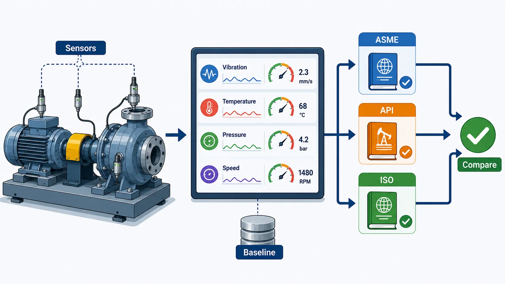
The comparison process should follow a controlled sequence:
Real-Time Data → Data Validation → Operating Condition Review → Applicable Requirement → Baseline Comparison → Deviation Analysis → Risk Assessment → Engineering Decision
Each stage helps prevent incorrect interpretation.
Data Validation Before Comparison
Before comparing data against standards, the engineer should confirm that the measurements are credible.
Checks may include:
- Sensor identification.
- Calibration status.
- Data timestamp.
- Measurement units.
- Sensor condition.
- Sampling frequency.
- Data completeness.
- Instrument range.
- Operating state.
Poor-quality data can produce misleading conclusions.
Importance of Measurement Units
Unit consistency is essential.
For example, pressure data may be recorded using different units, while temperature may be reported using different scales.
Before comparison, engineers should verify:
- Unit system.
- Conversion accuracy.
- Decimal precision.
- Sensor configuration.
- Reporting convention.
A numerical value cannot be compared responsibly until its meaning and units are confirmed.
Considering Operating Conditions
Mechanical performance varies with operating conditions.
A pump operating at one load may produce different vibration and temperature behaviour from the same pump operating at another load.
Therefore, engineers should consider:
- Load.
- Speed.
- Temperature.
- Pressure.
- Flow.
- Process condition.
- Start-up or shutdown status.
- Ambient conditions.
Comparing measurements without considering operating state can produce false conclusions.
Example: Pump Performance
A centrifugal pump shows increasing vibration.
Real-time data indicates:
- Increased vibration.
- Slight bearing temperature increase.
- Reduced flow.
- Increased operating hours.
A basic evaluation might identify vibration as the primary concern.
A more professional evaluation considers the combined pattern.
Possible considerations include:
- Operating condition.
- Alignment.
- Bearing condition.
- Hydraulic behaviour.
- Foundation condition.
- Maintenance history.
The engineer then compares the observed behaviour with applicable equipment requirements and historical baseline information.
Example: Compressor Performance
A process compressor shows a gradual increase in vibration while operating under a stable load.
The engineering team compares:
- Current vibration.
- Historical trend.
- Operating speed.
- Temperature.
- Previous maintenance.
- Applicable requirements.
The trend may indicate developing deterioration even if the current reading has not reached an intervention threshold.
This demonstrates why trend analysis should complement absolute limit comparison.
Performance Thresholds
Performance thresholds can support early identification of abnormal conditions.
Thresholds may be associated with:
- Normal operation.
- Increased monitoring.
- Investigation.
- Maintenance planning.
- Immediate intervention.
However, threshold values must come from appropriate technical sources and equipment-specific requirements rather than arbitrary organisational assumptions.
Baseline Versus Standard
A baseline and a standard serve different purposes.
The baseline describes expected or historically verified equipment behaviour.
A standard establishes a technical framework or requirement.
Both may be useful.
For example:
- Baseline: historical vibration behaviour under a defined operating condition.
- Standard requirement: applicable technical criterion for evaluating that equipment or condition.
An engineer should not automatically treat historical performance as proof of compliance.
Real-Time Monitoring Systems
Modern mechanical systems may use:
- Sensors.
- Data acquisition systems.
- Condition-monitoring platforms.
- Supervisory control systems.
- Automated alarms.
- Trend dashboards.
- Digital maintenance systems.
These systems can provide continuous information about equipment behaviour.
However, automated monitoring does not eliminate engineering judgement.
Data Quality Controls
Real-time monitoring systems should be periodically checked.
Important controls include:
- Sensor calibration.
- Sensor health.
- Data validation.
- Timestamp synchronisation.
- Data storage.
- Alarm configuration.
- Communication reliability.
- Data security.
A faulty sensor can create an apparent mechanical problem that does not actually exist.
Recognising False Signals
An abnormal reading does not automatically prove equipment failure.
Potential causes include:
- Sensor malfunction.
- Calibration error.
- Loose connection.
- Environmental interference.
- Temporary process disturbance.
- Data transmission error.
- Incorrect configuration.
Therefore, abnormal data should be investigated and corroborated where appropriate.
Cross-Checking Performance Data
Where a critical deviation is identified, engineers may compare:
- Multiple sensors.
- Historical records.
- Physical inspection.
- Maintenance records.
- Operator observations.
- Independent measurements.
- Test results.
Cross-checking strengthens confidence in the engineering conclusion.
Performance Trend Analysis
Trend analysis examines how performance changes over time.
Useful trend characteristics include:
- Stable performance.
- Gradual deterioration.
- Sudden deterioration.
- Cyclic variation.
- Intermittent abnormality.
- Repeated excursions.
Each pattern can have different engineering significance.
Sudden Versus Gradual Changes
A sudden increase in a mechanical parameter may require immediate investigation.
A gradual increase may indicate progressive deterioration.
Both can be important, but they require different responses.
The engineer should consider:
- Magnitude.
- Rate of change.
- Equipment criticality.
- Operating conditions.
- Historical behaviour.
- Potential failure consequences.
Comparing Performance With Manufacturer Information
Manufacturer data can provide important reference information.
It may include:
- Operating ranges.
- Design conditions.
- Performance curves.
- Recommended limits.
- Maintenance requirements.
- Testing requirements.
Manufacturer information should be evaluated alongside applicable codes, standards, specifications, and actual service conditions.
International Standards and Organisational Requirements
An organisation may establish additional internal requirements beyond the minimum applicable standard.
The comparison process should therefore consider:
- Regulatory requirements.
- Applicable codes.
- International standards.
- Contractual requirements.
- Manufacturer requirements.
- Organisational specifications.
Where multiple requirements apply, the engineering team should establish which requirement governs the specific decision.
Managing Conflicting Requirements
If requirements appear inconsistent, the issue should be formally reviewed.
The team should:
- Identify the exact requirements.
- Confirm document revisions.
- Establish applicability.
- Consult responsible engineering authority.
- Document the interpretation.
- Update the applicable procedure if required.
Informal assumptions should be avoided.
Performance Comparison Process
A robust process can be structured into the following stages:
Stage 1: Identify the Equipment
Record:
- Equipment number.
- Type.
- Manufacturer.
- Model.
- Location.
- Service.
Stage 2: Define the Intended Function
Establish what the equipment must achieve.
Stage 3: Identify Critical Performance Metrics
Select relevant parameters.
Stage 4: Establish the Baseline
Use verified historical or commissioning information.
Stage 5: Identify Applicable Requirements
Determine the correct codes, standards and specifications.
Stage 6: Validate Real-Time Data
Check data quality and measurement reliability.
Stage 7: Compare Performance
Compare actual behaviour against applicable criteria and baseline.
Stage 8: Analyse Deviations
Determine magnitude, trend and significance.
Stage 9: Assess Risk
Consider safety, integrity, reliability and operational consequences.
Stage 10: Determine Action
Possible actions include:
- Continue monitoring.
- Increase inspection frequency.
- Investigate.
- Repair.
- Maintain.
- Restrict operation.
- Replace equipment.
- Conduct further testing.
Key Benefits
Improved Reliability
Continuous comparison can identify deterioration before failure.
Improved Safety
Abnormal mechanical conditions can be identified earlier.
Better Maintenance Planning
Maintenance can be prioritised using evidence.
Improved Asset Integrity
Performance data supports better mechanical integrity decisions.
Reduced Unplanned Downtime
Early intervention can prevent unexpected failures.
Better QA/QC Evidence
Objective performance information strengthens quality decisions.
Improved Regulatory Readiness
Documented comparison demonstrates systematic performance monitoring.
Better Resource Allocation
Engineering resources can be directed toward high-risk equipment.
Practical Example: Real-Time Bearing Monitoring
A critical rotating machine has continuous bearing temperature and vibration monitoring.
The historical baseline indicates stable behaviour under normal load.
Over several weeks:
- Vibration gradually increases.
- Bearing temperature rises slightly.
- Operating conditions remain relatively stable.
The engineering team validates the sensors and confirms that the measurements are credible.
The trend is compared with applicable technical requirements and organisational intervention criteria.
Rather than waiting for an outright failure, the team initiates a controlled investigation.
Possible actions include:
- Detailed vibration analysis.
- Physical inspection.
- Lubrication review.
- Alignment verification.
- Bearing condition assessment.
This approach demonstrates proactive mechanical reliability management.
Practical Example: Pressure System Performance
A mechanical pressure system operates with real-time pressure and temperature monitoring.
The pressure remains generally stable but periodically approaches a defined operating boundary.
The engineer reviews:
- Actual pressure.
- Temperature.
- Operating duration.
- Historical trends.
- Applicable design information.
- Inspection records.
The analysis determines whether the variation is expected operational behaviour or evidence of a developing problem.
The critical principle is that a reading should be interpreted in its engineering context rather than viewed in isolation.
Practical Example: API-Oriented Equipment Monitoring
A process facility monitors a rotating mechanical asset used in a critical production service.
The organisation identifies an applicable API framework for the equipment and maps relevant performance indicators against the requirements and established monitoring programme.
The review includes:
- Vibration trends.
- Temperature.
- Speed.
- Operating conditions.
- Maintenance history.
- Previous inspection results.
A gradual deterioration pattern is identified.
The organisation increases monitoring and schedules a controlled inspection rather than waiting for equipment failure.
Practical Example: ISO-Based Condition Monitoring
An organisation establishes a condition-monitoring programme for rotating machinery.
The programme integrates:
- Sensor data.
- Trend analysis.
- Inspection records.
- Maintenance history.
- Defined evaluation criteria.
The quality team uses the resulting information to identify changes in mechanical condition and support maintenance planning.
The process demonstrates how condition monitoring can form part of a broader asset-management and reliability strategy.
Common Errors in Performance Comparison
Several mistakes can reduce the value of real-time mechanical evaluation.
Using the Wrong Standard
A standard should never be selected simply because it is commonly used in the industry.
Comparing Data Without Operating Context
Performance values must be interpreted according to load, speed, temperature and service conditions.
Ignoring Historical Trends
A single acceptable measurement may conceal gradual deterioration.
Trusting Sensors Without Validation
Sensor faults can produce false alarms or missed conditions.
Treating Standards as Universal Limits
Different standards have different scopes and purposes.
Ignoring Manufacturer Requirements
Equipment-specific information can be important to correct interpretation.
Using Obsolete Requirements
The applicable edition or revision should be verified.
Making Decisions From One Parameter
Mechanical condition should often be evaluated using multiple relevant indicators.
Quality Assurance Controls
A QA/QC system should establish controls for:
- Data collection.
- Sensor calibration.
- Measurement traceability.
- Data validation.
- Standard identification.
- Document revision control.
- Engineering review.
- Decision approval.
- Record retention.
These controls improve confidence in the comparison process.
Documentation Requirements
Performance evaluations should be documented sufficiently to support later review.
Records may include:
- Equipment identification.
- Date and time.
- Operating conditions.
- Measured values.
- Units.
- Sensor identification.
- Applicable requirements.
- Baseline.
- Trend information.
- Engineering assessment.
- Action taken.
- Approval.
Engineering Decision-Making
The final decision should be based on evidence.
Possible decisions include:
- Performance acceptable.
- Continue routine monitoring.
- Increase monitoring.
- Conduct additional inspection.
- Schedule maintenance.
- Conduct further testing.
- Restrict operating conditions.
- Remove equipment from service.
The decision should reflect the significance of the deviation and the consequences of failure.
Risk-Based Interpretation
The same deviation can have different significance depending on equipment criticality.
For example, a minor deviation on non-critical equipment may require monitoring, while the same deviation on safety-critical equipment may require immediate engineering evaluation.
Risk assessment should consider:
- Failure probability.
- Failure consequence.
- Equipment criticality.
- Personnel exposure.
- Environmental impact.
- Production impact.
- Mechanical integrity.
Integrating Real-Time Data With QA/QC
Real-time performance data should not exist separately from the quality system.
It should connect with:
- Inspection planning.
- Maintenance management.
- NCR systems.
- Asset registers.
- Engineering change control.
- Audit records.
- Reliability analysis.
This integration allows data to support broader engineering decisions.
Role of the Mechanical QA/QC Engineer
The QA/QC engineer should:
- Confirm applicable requirements.
- Verify data quality.
- Review performance trends.
- Assess deviations.
- Coordinate engineering evaluation.
- Maintain traceability.
- Verify corrective actions.
- Support audit evidence.
- Ensure controlled documentation.
The role requires both technical understanding and professional judgement.
Role of Maintenance Teams
Maintenance personnel can contribute:
- Equipment history.
- Previous failure information.
- Maintenance findings.
- Component replacement records.
- Lubrication information.
- Repair history.
Combining maintenance knowledge with real-time data improves reliability evaluation.
Role of Operations Personnel
Operators may identify:
- Unusual noise.
- Changes in vibration.
- Temperature changes.
- Leakage.
- Process instability.
- Start-up abnormalities.
Operator observations can provide useful supporting evidence alongside instrumented data.
Compliance Review Cycle
A sustainable comparison programme can follow:
Monitor → Validate → Compare → Analyse → Assess → Act → Verify → Trend
This cycle should be repeated throughout the equipment lifecycle.
Case Study: Comparing Real-Time Pump Performance With Applicable Requirements
Background
A manufacturing facility operates a critical pump that supports a continuous production process. The pump is fitted with sensors that monitor vibration, temperature, pressure and flow.
The organisation has established historical baseline information and identifies applicable technical requirements for the equipment.
Initial Observation
The monitoring system detects a gradual increase in vibration.
The current value remains within the organisation’s normal operating range, but the trend is significantly different from the historical baseline.
Data Validation
The QA/QC and maintenance teams verify:
- Sensor identification.
- Calibration status.
- Data timestamps.
- Operating load.
- Pump speed.
- Process conditions.
The data is confirmed as credible.
Engineering Comparison
The team compares the current trend with:
- Historical performance.
- Applicable technical requirements.
- Manufacturer information.
- Maintenance history.
The analysis indicates that continued operation should be accompanied by increased monitoring and further investigation.
Investigation
The team performs additional checks on:
- Alignment.
- Bearing condition.
- Foundation condition.
- Operating conditions.
- Lubrication.
A developing mechanical issue is identified before major equipment failure occurs.
Outcome
The organisation schedules corrective maintenance during a controlled shutdown.
The pump is subsequently returned to service, and the performance trend is monitored.
The case demonstrates the value of comparing real-time data with appropriate engineering requirements rather than waiting for an obvious failure.
Conclusion
Comparing real-time mechanical performance metrics against recognised international engineering codes and standards provides an evidence-based foundation for evaluating equipment condition, reliability, mechanical integrity, and operational performance. Effective comparison requires more than checking whether a measured value appears acceptable. Engineers must establish the correct technical requirements, verify standard applicability, validate measurement data, understand operating conditions, establish reliable baselines, analyse trends, and apply professional engineering judgement.
ASME, API, and ISO frameworks can provide important technical reference points, but their applicability depends on the specific equipment, industry, service conditions, project requirements, and scope of the relevant document. A professional QA/QC approach therefore maps applicable requirements to actual equipment performance rather than applying generic limits without context. Real-time data becomes particularly valuable when combined with historical trends, inspection findings, maintenance records, manufacturer information, and condition-monitoring evidence.
A well-controlled performance comparison system enables organisations to identify deterioration earlier, prioritise maintenance, reduce unplanned downtime, strengthen mechanical integrity, improve operational reliability, and support compliance decisions. The most effective approach is a continuous cycle of monitoring, validation, comparison, analysis, risk assessment, action, and verification. When embedded within the wider mechanical QA/QC and asset-management framework, this approach supports safer, more reliable, and more efficient mechanical engineering operations while providing objective evidence that equipment performance is being systematically evaluated against appropriate international engineering requirements.
2: Calculate Mechanical Reliability Factors and Operational Lifespans Using System Run-Time Data, Wear-and-Tear Models, and Historical Maintenance Logs
Calculating mechanical reliability factors and estimating operational lifespan are essential activities within advanced mechanical engineering, QA/QC, maintenance, asset integrity, and reliability management. Mechanical equipment does not normally fail simply because it reaches a particular age. Its condition is influenced by operating hours, load cycles, temperature, vibration, lubrication, alignment, material properties, environmental conditions, maintenance quality, operating practices, and the severity of service. A reliable lifespan assessment therefore requires engineers to combine real operating data with historical maintenance evidence and appropriate engineering models.
Run-time data provides information about how much service equipment has experienced, while maintenance records reveal how the equipment has behaved throughout its operating history. Wear-and-tear models provide a structured method for interpreting deterioration and estimating future performance. When these information sources are combined, engineers can move from reactive maintenance towards evidence-based reliability management. Instead of replacing components solely according to fixed calendar intervals, engineering teams can use condition, utilisation, failure history, and degradation trends to determine when inspection, repair, refurbishment, or replacement is justified.
A professional reliability assessment must also recognise uncertainty. An estimated remaining operational life is not an absolute prediction of the exact date on which equipment will fail. It is an engineering estimate based on available evidence, assumptions, historical behaviour, operating conditions, and applicable models. The quality of the result therefore depends on the quality of the underlying data and the suitability of the model used. For safety-critical mechanical systems, reliability calculations should be supported by appropriate engineering review, inspection evidence, manufacturer information, applicable codes or standards, and defined acceptance criteria.
Understanding Mechanical Reliability
Mechanical reliability describes the probability that equipment will perform its intended function for a specified period under defined operating conditions.
Reliability should be considered in relation to:
- Intended function.
- Operating environment.
- Service conditions.
- Operating duration.
- Load.
- Maintenance strategy.
- Failure mechanisms.
- Component criticality.
- Required performance.
A component may be reliable under one operating condition but experience accelerated deterioration under another.
Reliability and Availability
Reliability and availability are related but different concepts.
Reliability concerns the ability of equipment to perform without failure over a defined period.
Availability considers whether the equipment is capable of performing its function when required, taking account of failures and restoration activities.
A system may therefore have:
- High reliability and high availability.
- High reliability but poor availability due to long repair periods.
- Lower reliability but relatively high availability if repairs are rapid.
Both concepts are useful in mechanical performance evaluation.
Key Definitions and Concepts
| Term | Definition | Mechanical Engineering Application |
|---|---|---|
| Reliability | Probability of performing the required function for a defined period | Evaluating equipment failure behaviour |
| Availability | Proportion of time equipment is capable of performing its function | Assessing operational readiness |
| Failure Rate | Frequency at which failures occur within a defined population or period | Supporting reliability analysis |
| Mean Time Between Failures | Average operating time between failures for repairable equipment | Evaluating equipment reliability |
| Mean Time To Repair | Average time required to restore equipment after failure | Supporting availability analysis |
| Run-Time | Period during which equipment operates | Establishing service exposure |
| Operating Hours | Accumulated hours of equipment operation | Supporting life estimation |
| Wear Rate | Rate at which a component loses functional condition | Estimating degradation |
| Degradation | Progressive deterioration of equipment condition | Monitoring remaining life |
| Remaining Useful Life | Estimated future service period before defined intervention or end-of-life condition | Supporting maintenance decisions |
| Maintenance Log | Historical record of maintenance activities and findings | Identifying recurring deterioration |
| Failure Mode | Specific way in which equipment can fail | Supporting reliability assessment |
| Failure Mechanism | Physical or operational process causing failure | Understanding degradation |
| Life Model | Mathematical or engineering method for estimating service life | Supporting lifespan prediction |
| Hazard Rate | Conditional rate of failure at a particular point in life | Analysing failure behaviour |
| Reliability Function | Probability of surviving without failure to a given time | Supporting reliability calculations |
| Preventive Maintenance | Planned action intended to prevent or reduce failure | Extending equipment service life |
| Corrective Maintenance | Action performed to restore equipment after a defect or failure | Returning equipment to service |
| Condition Monitoring | Assessment of equipment condition using measurable indicators | Supporting predictive decisions |
| Criticality | Significance of equipment failure to safety or operations | Prioritising reliability controls |
Why Run-Time Data Matters
Operating hours provide a basic measure of equipment exposure.
For example, two identical pumps may both have been installed for five years, but one may have operated continuously while the other operated intermittently.
Calendar age alone would therefore provide an incomplete basis for lifespan estimation.
Run-time information may include:
- Total operating hours.
- Start-stop cycles.
- Load cycles.
- Speed.
- Temperature exposure.
- Pressure cycles.
- Duty cycles.
- Standby periods.
- Operating environment.
Operating Hours and Component Exposure
Accumulated operating hours can be used to identify maintenance and inspection points.
However, operating hours should not be interpreted in isolation.
A machine operating for 5,000 hours under moderate load may experience less degradation than another machine operating for 3,000 hours under severe conditions.
The engineering assessment should therefore consider both duration and severity.
Understanding Wear and Tear
Wear and tear describes progressive physical deterioration caused by continued use and environmental exposure.
Mechanical wear may result from:
- Friction.
- Repeated loading.
- Surface contact.
- Abrasion.
- Erosion.
- Corrosion.
- Thermal cycling.
- Vibration.
- Misalignment.
- Lubrication deficiencies.
Different components experience different degradation mechanisms.
Common Mechanical Degradation Mechanisms
Abrasive Wear
Material is removed through contact with harder particles or surfaces.
Adhesive Wear
Material transfers between contacting surfaces due to local interaction.
Fatigue
Repeated loading produces progressive damage that may eventually result in cracking or failure.
Corrosion
Material degradation occurs through chemical or electrochemical interaction with the environment.
Erosion
Material is progressively removed through high-velocity fluid or particle interaction.
Thermal Degradation
Repeated or excessive temperature exposure may reduce material or component performance.
Fretting
Small-amplitude relative movement between contacting surfaces can produce local damage.
Understanding the dominant mechanism is essential before selecting an appropriate lifespan model.
Historical Maintenance Logs
Maintenance records provide valuable evidence about actual equipment behaviour.
Useful information includes:
- Failure dates.
- Component replacements.
- Repair dates.
- Inspection results.
- Lubrication activities.
- Alignment work.
- Bearing replacements.
- Vibration findings.
- Temperature observations.
- Leakage events.
- Previous corrective actions.
- Recurring defects.
Historical records can reveal patterns that are not obvious from current operating data.
Building a Reliable Equipment History
An effective equipment history should connect:
Equipment ID → Operating Hours → Maintenance → Failure Events → Inspection Findings → Repairs → Current Condition
This traceability enables more reliable engineering analysis.
Data Quality Before Reliability Calculation
Reliability calculations are only as credible as the data used.
Before performing calculations, engineers should verify:
- Equipment identification.
- Operating-hour records.
- Failure dates.
- Maintenance dates.
- Component replacement records.
- Inspection results.
- Measurement units.
- Missing data.
- Duplicate entries.
- Data inconsistencies.
Incorrect data can significantly distort reliability estimates.
Establishing the Observation Period
A reliability analysis should define the period being evaluated.
The observation period may be:
- One year.
- Several years.
- A defined production campaign.
- A specific equipment lifecycle.
- A component population.
- A defined number of operating cycles.
The chosen period should provide sufficient evidence for the intended analysis.
Basic Reliability Calculation
For a simplified population where failures are recorded over a defined operating period, an approximate failure rate can be calculated as:
Failure Rate = Number of Failures ÷ Total Operating Time
For example, if a group of similar mechanical units records 4 failures over 20,000 total operating hours:
Failure Rate = 4 ÷ 20,000
This produces a simplified failure rate of:
0.0002 failures per operating hour.
This value can then be used as one input to broader reliability analysis, provided the assumptions behind the calculation are appropriate.
Mean Time Between Failures
For repairable equipment, a simplified MTBF calculation can be expressed as:
MTBF = Total Operating Time ÷ Number of Failures
If equipment operates for 20,000 hours and experiences four relevant failures:
MTBF = 20,000 ÷ 4
MTBF = 5,000 hours.
MTBF should be interpreted carefully because it is an average and does not mean that every unit will operate exactly 5,000 hours before failure.
Mean Time To Repair
MTTR can be calculated as:
MTTR = Total Repair Time ÷ Number of Repairs
For example, if four repairs require a combined 40 hours:
MTTR = 40 ÷ 4
MTTR = 10 hours.
This information helps assess restoration efficiency and equipment availability.
Availability Calculation
A simplified inherent availability relationship can be expressed as:
Availability = MTBF ÷ (MTBF + MTTR)
Using:
- MTBF = 5,000 hours.
- MTTR = 10 hours.
Availability becomes:
5,000 ÷ 5,010
This indicates very high theoretical availability, subject to the assumptions of the simplified model.
Actual operational availability may be affected by:
- Planned maintenance.
- Waiting time.
- Spare-parts availability.
- Staffing.
- Production constraints.
- Inspection requirements.
- External dependencies.
Reliability Function
Reliability can be expressed conceptually as:
R(t) = Probability that equipment performs its required function through time t.
For some simplified constant failure-rate assumptions, reliability may be represented by an exponential model:
R(t) = e^(-λt)
where:
- R(t) = reliability at time t.
- λ = assumed constant failure rate.
- t = operating time.
This model should not automatically be applied to every mechanical system because actual failure behaviour may change throughout the equipment lifecycle.
Failure Rate and Equipment Life
Failure behaviour may change as equipment ages.
A common conceptual representation is the bathtub curve, consisting of:
- Early-life failures.
- Relatively stable useful-life behaviour.
- Increasing wear-out failures.
This model is useful for explaining different stages of equipment reliability.
However, actual equipment may not follow a simple bathtub curve.
Early-Life Failures
Early failures may arise from:
- Manufacturing defects.
- Installation errors.
- Incorrect assembly.
- Commissioning problems.
- Inadequate procedures.
- Initial adjustment issues.
These failures may decline after initial corrective action.
Useful-Life Period
During a stable operating period, failures may occur at a relatively consistent rate.
Maintenance and condition monitoring can help maintain performance.
Wear-Out Period
As components age, deterioration may increase because of:
- Fatigue.
- Wear.
- Corrosion.
- Material degradation.
- Repeated thermal cycling.
- Increasing clearances.
At this stage, inspection and replacement planning become increasingly important.
Remaining Useful Life
Remaining Useful Life, or RUL, is an estimate of how much additional service a component may provide before reaching a defined intervention or end-of-life condition.
RUL should be based on evidence such as:
- Current condition.
- Historical degradation.
- Operating exposure.
- Inspection results.
- Failure history.
- Wear models.
- Manufacturer information.
- Engineering assessment.
Simple Remaining-Life Example
Suppose a component historically reaches approximately 12,000 operating hours before requiring replacement.
A particular component has accumulated 8,500 hours.
A simple remaining-life estimate could be:
12,000 − 8,500 = 3,500 hours.
However, this does not mean the component is guaranteed to last another 3,500 hours.
The estimate must be adjusted if current inspection data shows accelerated degradation.
Wear-Rate Model
A simple linear wear model may be represented as:
Wear Rate = Change in Wear ÷ Operating Time
For example, if a component loses 0.20 mm of usable thickness over 2,000 hours:
Wear Rate = 0.20 ÷ 2,000
Wear Rate = 0.0001 mm per operating hour.
If the remaining allowable wear is known, an indicative remaining service period can be estimated.
Limitations of Linear Wear Models
Linear models are useful for simple trend analysis but may not represent real deterioration accurately.
Wear can accelerate because of:
- Increasing temperature.
- Poor lubrication.
- Increased loading.
- Surface damage.
- Corrosion.
- Misalignment.
- Changing process conditions.
Therefore, the engineer should verify whether the observed trend supports a linear assumption.
Historical Maintenance Trend Analysis
Maintenance records should be analysed for patterns.
The quality team may examine:
- Failure frequency.
- Component replacement frequency.
- Repair duration.
- Recurring failure modes.
- Failure location.
- Operating hours at failure.
- Maintenance intervals.
Recurring patterns can indicate that the current maintenance strategy requires improvement.
Practical Example: Bearing Reliability
A rotating machine has experienced repeated bearing replacements.
Historical records show:
- First replacement: 9,000 operating hours.
- Second replacement: 8,400 hours.
- Third replacement: 7,900 hours.
The declining service period suggests that the issue may not simply be normal ageing.
The engineering team should investigate:
- Lubrication.
- Alignment.
- Loading.
- Installation.
- Shaft condition.
- Vibration.
- Operating environment.
Replacing bearings at shorter intervals without addressing the underlying mechanism may not improve reliability.
Maintenance Interval Analysis
Historical maintenance records can help determine whether maintenance intervals are appropriate.
The team may compare:
- Planned interval.
- Actual failure time.
- Inspection findings.
- Component condition.
- Repair history.
If components consistently fail before the planned interval, the maintenance strategy should be reviewed.
If components remain in excellent condition far beyond the planned interval, condition-based approaches may be worth evaluating where technically appropriate.
Preventive Maintenance Effectiveness
Preventive maintenance should be assessed using evidence.
Useful indicators include:
- Failure frequency.
- Unplanned downtime.
- Repeat failures.
- Component life.
- Maintenance cost.
- Inspection findings.
- Emergency repairs.
A high number of preventive maintenance activities does not automatically mean the strategy is effective.
Reliability-Centred Thinking
Reliability analysis should focus on how equipment fails and what consequences result.
For each critical component, consider:
- Intended function.
- Functional failure.
- Failure mode.
- Failure mechanism.
- Failure consequence.
- Detection method.
- Preventive control.
- Corrective action.
This supports better maintenance and reliability decisions.
Component Criticality
Criticality should influence lifespan assessment.
A component may be considered highly critical where failure could result in:
- Serious safety consequences.
- Major production interruption.
- Significant equipment damage.
- Environmental consequences.
- Loss of essential system function.
Higher-criticality components require stronger evidence before extending operating life.
Calculating Operational Exposure
Engineers can calculate cumulative operating exposure using:
Total Exposure = Sum of Valid Operating Periods
Where operating data contains interruptions, the periods should be reviewed carefully to avoid double counting.
Relevant exposure may also include:
- Number of starts.
- Number of shutdowns.
- Load cycles.
- Pressure cycles.
- Thermal cycles.
For some failure mechanisms, cycles may be more significant than total operating hours.
Cyclic Loading
Mechanical fatigue may depend strongly on repeated loading.
Useful parameters include:
- Number of cycles.
- Load amplitude.
- Stress range.
- Operating frequency.
- Cycle history.
An engineer should therefore avoid assuming that operating hours alone represent total mechanical exposure.
Maintenance Log Normalisation
Historical records may use inconsistent terminology.
For example:
- “Bearing replaced”.
- “Bearing renewed”.
- “New bearing fitted”.
- “Bearing changed”.
These may represent the same activity.
Data should therefore be standardised before statistical analysis.
Reliability Data Quality Checks
The engineering team should identify:
- Missing failure dates.
- Missing operating hours.
- Duplicate failures.
- Incorrect equipment IDs.
- Unclear repair records.
- Unrecorded component changes.
- Inconsistent failure classifications.
This improves the credibility of calculations.
Using Failure Distribution Models
Where sufficient historical data exists, engineers may use statistical models to understand failure behaviour.
Potential approaches include:
- Exponential models.
- Weibull analysis.
- Lognormal models.
- Reliability distributions.
The selected model should reflect the available data and engineering context.
Weibull Analysis
Weibull analysis can be useful for examining different failure behaviours.
Its shape parameter can help indicate whether failure behaviour is associated conceptually with:
- Early-life failures.
- Random failures.
- Increasing wear-out failures.
However, reliable application requires appropriate data quality and statistical competence.
Engineering Use of Reliability Models
Reliability models should support engineering decisions rather than replace engineering judgement.
They can help determine:
- Inspection frequency.
- Maintenance strategy.
- Replacement timing.
- Spare-parts requirements.
- Criticality priorities.
- Reliability improvement opportunities.
Combining Models With Inspection Evidence
A model might predict a remaining life of a certain duration.
However, a physical inspection could reveal unexpected cracking or accelerated wear.
The physical evidence may require the predicted lifespan to be reconsidered.
This demonstrates the importance of combining:
Model + Monitoring + Inspection + Maintenance History + Engineering Judgement
Operational Lifespan Versus Design Life
Design life and operational lifespan are not always identical.
Design life may represent the period for which the equipment was designed under defined assumptions.
Actual operational lifespan depends on:
- Service conditions.
- Maintenance.
- Loading.
- Environment.
- Degradation.
- Inspection results.
- Repair history.
Equipment may require intervention before its nominal design period or may continue safely under controlled conditions where appropriate engineering assessment supports it.
Factors Affecting Operational Lifespan
Important factors include:
- Operating temperature.
- Pressure.
- Mechanical loading.
- Speed.
- Vibration.
- Lubrication.
- Alignment.
- Corrosion.
- Contamination.
- Start-stop frequency.
- Maintenance quality.
- Installation quality.
- Environmental exposure.
Practical Example: Gearbox Lifespan
A gearbox has a historical replacement interval of approximately 30,000 operating hours.
Current data indicates:
- 24,000 operating hours.
- Increasing vibration.
- Slight temperature increase.
- No major recent repairs.
- Increased production load.
A simple calendar or run-time calculation might suggest that 6,000 hours remain.
However, the current degradation indicators suggest that this estimate is overly optimistic.
The engineering team therefore conducts further condition assessment before making a lifespan decision.
Practical Example: Pump Maintenance History
A pump has accumulated 18,000 operating hours.
Historical records show:
- Two seal replacements.
- One bearing replacement.
- Several alignment corrections.
- Increasing vibration during recent operation.
The data suggests that the pump’s service history contains recurring mechanical issues.
The engineer should not estimate remaining life solely from operating hours. The maintenance pattern should be investigated to identify whether a systemic issue is accelerating deterioration.
Practical Example: Compressor Reliability
A compressor fleet contains ten similar units.
Over several years, the organisation records:
- Operating hours.
- Failure events.
- Repair durations.
- Component replacements.
The analysis indicates that several units experience similar failures at comparable service exposure.
This may support a fleet-level reliability review rather than treating each failure as an isolated event.
Reliability Improvement Actions
Where reliability calculations identify weaknesses, possible actions include:
- Adjusting maintenance intervals.
- Increasing condition monitoring.
- Improving lubrication.
- Correcting alignment.
- Reviewing operating conditions.
- Replacing degraded components.
- Improving inspection methods.
- Revising procedures.
- Training maintenance personnel.
- Reviewing equipment design.
Key Benefits
Improved Maintenance Planning
Reliability calculations provide evidence for maintenance timing.
Reduced Unexpected Failure
Early identification of deterioration can reduce sudden equipment failures.
Better Asset Life Management
Engineering teams can make more informed decisions about continued operation.
Improved Resource Allocation
Maintenance resources can be directed toward critical equipment.
Reduced Lifecycle Cost
Evidence-based maintenance can reduce unnecessary replacements and avoid major failures.
Improved Safety
Reliability analysis supports better control of mechanically critical equipment.
Better QA/QC Decisions
Historical evidence provides stronger justification for inspection and maintenance decisions.
Common Errors in Lifespan Calculation
Relying Only on Calendar Age
Calendar age does not represent actual operating exposure.
Relying Only on Operating Hours
Different loads and environments produce different degradation rates.
Ignoring Maintenance History
Past repairs and failures provide valuable evidence.
Assuming Constant Failure Rate
Failure behaviour may change throughout equipment life.
Ignoring Current Condition
Historical averages cannot replace current inspection evidence.
Treating Predictions as Guarantees
A lifespan estimate contains uncertainty.
Using Poor Data
Incomplete or inconsistent records can produce misleading results.
Reliability Assessment Procedure

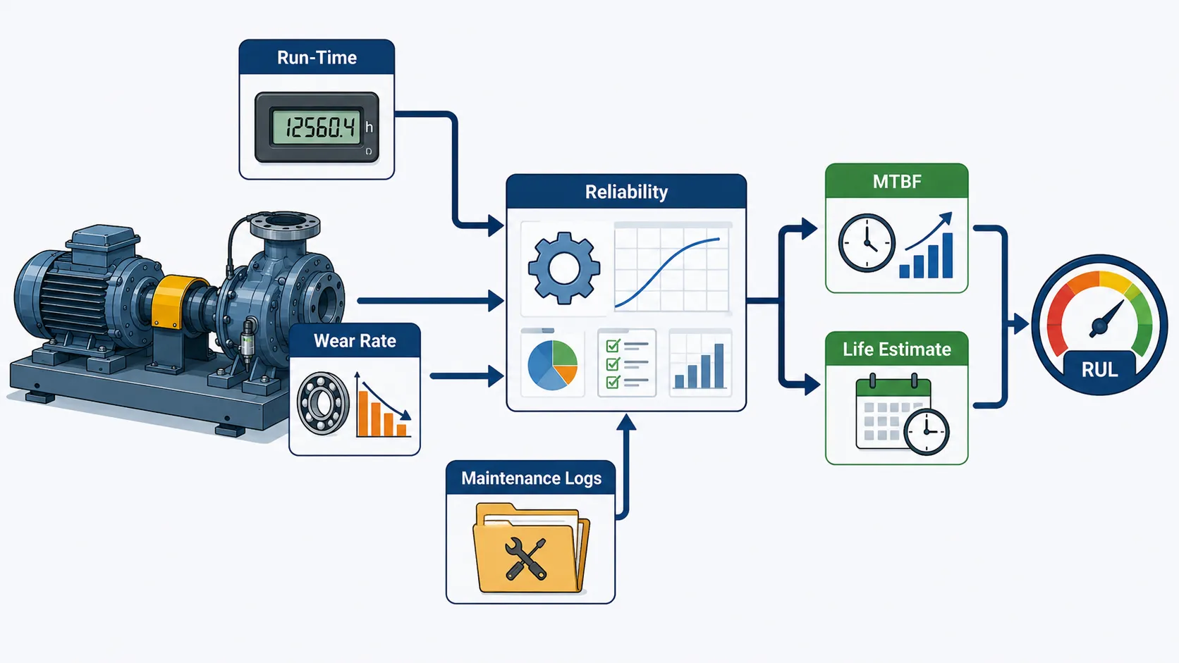
A structured procedure may include:
Step 1: Identify Equipment
Confirm asset number, type, manufacturer and service.
Step 2: Establish Criticality
Determine consequences of failure.
Step 3: Collect Run-Time Data
Obtain operating hours and relevant cycle information.
Step 4: Review Maintenance History
Identify failures, repairs and component changes.
Step 5: Identify Failure Mechanisms
Determine the dominant deterioration mechanisms.
Step 6: Assess Current Condition
Use inspection and condition-monitoring evidence.
Step 7: Calculate Reliability Indicators
Calculate appropriate factors such as failure rate, MTBF or availability.
Step 8: Develop Degradation Model
Use an appropriate wear or statistical model where justified.
Step 9: Estimate Remaining Life
Estimate potential remaining service under defined assumptions.
Step 10: Apply Engineering Judgement
Review uncertainty and consequences.
Step 11: Determine Action
Select monitoring, maintenance, repair, replacement or further assessment.
Step 12: Record and Review
Document the assessment and update it as new evidence becomes available.
Case Study: Estimating the Remaining Life of a Critical Pump
Background
A production facility operates a critical pump continuously. The pump has accumulated 28,000 operating hours.
The organisation maintains historical records showing:
- Previous bearing replacements.
- Seal replacements.
- Alignment corrections.
- Vibration measurements.
- Maintenance dates.
- Failure events.
Initial Reliability Assessment
The maintenance database shows that comparable pumps have historically operated for approximately 35,000 hours before major refurbishment.
A simple run-time estimate therefore suggests approximately:
35,000 − 28,000 = 7,000 hours.
However, the engineering team does not treat this as a guaranteed remaining life.
Current Condition
Recent monitoring shows:
- Gradually increasing vibration.
- Slight bearing temperature increase.
- Stable operating speed.
- Increased production loading.
The team validates the sensor information and confirms the data is reliable.
Historical Comparison
The historical records show that similar vibration increases previously occurred before bearing deterioration.
The current trend is therefore considered significant.
Engineering Assessment
The team reviews:
- Operating hours.
- Current vibration.
- Temperature trend.
- Maintenance history.
- Loading.
- Inspection evidence.
The estimated remaining life is revised from a simple run-time estimate to a condition-based assessment requiring further inspection.
Action
The organisation:
- Increases monitoring frequency.
- Conducts additional inspection.
- Reviews alignment.
- Checks lubrication.
- Plans controlled maintenance.
Outcome
A developing bearing condition is identified before catastrophic failure.
The case demonstrates that operational lifespan should be calculated using multiple evidence sources rather than relying solely on nominal service hours.
Conclusion
Calculating mechanical reliability factors and operational lifespans requires a structured combination of system run-time data, historical maintenance records, current equipment condition, wear-and-tear models, failure information, and professional engineering judgement. Operating hours provide an important measure of exposure, but they should be interpreted alongside load cycles, environmental conditions, temperature, vibration, lubrication, maintenance history, and known degradation mechanisms. Reliability indicators such as failure rate, MTBF, MTTR, availability, and reliability functions can provide useful quantitative evidence when their assumptions and limitations are understood.
Wear models and statistical reliability techniques can help estimate deterioration and remaining useful life, but these estimates should never be treated as guaranteed failure predictions. A component with an apparently favourable historical service life may deteriorate more rapidly because of changed operating conditions, poor maintenance, increased loading, corrosion, misalignment, or another emerging failure mechanism. For this reason, reliability calculations should be continuously reviewed against inspection findings and current condition-monitoring evidence.
A robust mechanical reliability programme combines quantitative analysis with practical engineering knowledge. The process should establish equipment criticality, validate operational data, analyse maintenance history, identify failure mechanisms, calculate relevant reliability factors, model degradation where appropriate, estimate remaining life, assess uncertainty, and determine proportionate engineering action. When embedded within mechanical QA/QC, asset integrity, maintenance, and operational excellence systems, this approach supports safer equipment operation, more effective maintenance planning, reduced unplanned downtime, improved resource allocation, and more defensible decisions concerning the continued service life of critical mechanical systems.
3: Produce Strategic Engineering Recommendations Detailing Structural Upgrades or Operational Changes Needed to Achieve Long-Term Performance Excellence
Long-term mechanical performance excellence requires engineering organisations to move beyond identifying defects and responding to individual failures. Strategic engineering recommendations provide a structured route for converting inspection findings, reliability data, performance trends, maintenance history, operational experience, and compliance information into practical improvements. The objective is to ensure that mechanical systems remain safe, reliable, efficient, maintainable, and capable of meeting their intended service requirements throughout their operational lifecycle.
A strategic recommendation should therefore explain not only what needs to change, but also why the change is necessary, what evidence supports it, what risks it addresses, how it should be implemented, and how its effectiveness will be verified. Recommendations may involve structural upgrades, equipment modification, process optimisation, improved inspection arrangements, revised maintenance strategies, operating-condition changes, enhanced monitoring, component replacement, or changes to engineering procedures. The most effective recommendations balance technical performance with safety, reliability, cost, maintainability, resource availability, operational continuity, and applicable engineering requirements.
For mechanical QA/QC and engineering management, recommendations must be evidence-based and technically defensible. A proposed modification should be supported by relevant inspection results, test data, historical failure information, reliability calculations, engineering drawings, manufacturer information, applicable codes and standards, and risk evaluation. Where a structural or mechanical modification is significant, the recommendation should also recognise the need for appropriate engineering design review, verification, approval, inspection, testing, and controlled implementation before the modified system is returned to service.
Understanding Strategic Engineering Recommendations
A strategic engineering recommendation is a technically justified proposal intended to improve the future performance, reliability, integrity, safety, or efficiency of a mechanical system.
Unlike a routine maintenance instruction, a strategic recommendation considers longer-term performance.
It may address:
- Equipment design.
- Structural integrity.
- Mechanical reliability.
- Operating conditions.
- Inspection strategy.
- Maintenance strategy.
- Monitoring systems.
- Component selection.
- Process efficiency.
- Asset lifecycle.
- Quality control.
- Operational risk.
The recommendation should connect the identified engineering problem with an appropriate and measurable improvement.
Strategic Versus Routine Engineering Actions
Routine actions generally address immediate maintenance needs.
Strategic actions consider the wider system.
For example, replacing a failed bearing is a corrective action, whereas investigating why bearings repeatedly fail and redesigning the associated alignment, lubrication, monitoring, or loading controls is a strategic improvement.
Strategic thinking therefore asks:
- Why did the problem occur?
- Is the problem recurring?
- Is the current design adequate?
- Are operating conditions contributing?
- Can the failure mechanism be controlled?
- What improvement will prevent recurrence?
- How will effectiveness be measured?
Key Definitions and Concepts
| Term | Definition | Engineering Application |
|---|---|---|
| Strategic Recommendation | Evidence-based proposal for long-term improvement | Guides engineering investment |
| Structural Upgrade | Modification intended to improve structural capacity or integrity | Strengthening frames, supports or foundations |
| Operational Change | Modification to how equipment is operated | Adjusting loading or operating procedures |
| Performance Excellence | Sustained achievement of safety, reliability, efficiency and quality objectives | Long-term asset performance |
| Asset Integrity | Ability of an asset to perform its required function safely throughout its lifecycle | Protects mechanical systems |
| Reliability Improvement | Action intended to reduce failure probability or consequences | Improves equipment availability |
| Root Cause | Fundamental reason for a problem or failure | Prevents recurring failures |
| Risk Reduction | Reduction in probability or consequence of an unwanted event | Supports safer operations |
| Lifecycle Cost | Total cost associated with an asset throughout its lifecycle | Supports investment decisions |
| Maintainability | Ease and efficiency with which equipment can be inspected, maintained or repaired | Reduces downtime |
| Upgrade | Planned improvement to existing equipment or infrastructure | Extends capability or service life |
| Modification | Controlled change to equipment, system or process | Addresses identified engineering needs |
| Performance Baseline | Verified reference condition used for future comparison | Measures improvement |
| Verification | Confirmation that specified requirements have been achieved | Supports engineering acceptance |
| Validation | Confirmation that an improvement performs its intended function | Demonstrates practical effectiveness |
| Engineering Change | Controlled alteration to an approved technical arrangement | Prevents uncontrolled modifications |
Why Strategic Recommendations Are Important
A mechanical system can continue operating while gradually becoming less reliable.
Repeated corrective maintenance may temporarily restore performance without resolving the underlying cause.
Strategic recommendations help organisations:
- Address recurring problems.
- Reduce long-term failure risk.
- Improve equipment reliability.
- Extend useful service life.
- Improve mechanical integrity.
- Reduce unplanned downtime.
- Optimise maintenance expenditure.
- Improve safety.
- Strengthen compliance.
- Improve operational efficiency.
Evidence Required for Strategic Recommendations
Recommendations should be supported by reliable evidence.
Relevant evidence may include:
- Inspection findings.
- Test results.
- Vibration trends.
- Temperature trends.
- Pressure measurements.
- Flow measurements.
- Historical failure records.
- Maintenance logs.
- Non-conformance reports.
- Engineering drawings.
- Manufacturer information.
- Design calculations.
- Operating data.
- Reliability indicators.
- Previous modification records.
The stronger the evidence base, the more defensible the recommendation.
Establishing the Engineering Problem
Before recommending an upgrade or operational change, the actual problem must be clearly defined.
The engineering team should determine:
- What is underperforming?
- Where is the problem located?
- When does it occur?
- How frequently does it occur?
- What operating conditions are involved?
- What failure mechanism is suspected?
- What evidence confirms the problem?
- What are the consequences?
A vague problem statement produces vague recommendations.
Example of a Weak Problem Statement
“Pump performance needs improvement.”
This does not identify the engineering issue sufficiently.
Example of a Stronger Problem Statement
“Pump vibration has increased progressively under normal operating load, accompanied by repeated bearing replacement and declining operating reliability.”
The second statement provides a basis for engineering investigation.
Root Cause and Strategic Improvement
Strategic recommendations should address causes rather than symptoms.
A recurring mechanical problem may originate from:
- Incorrect alignment.
- Excessive loading.
- Inadequate support.
- Poor lubrication.
- Incorrect operating procedure.
- Structural resonance.
- Component selection.
- Thermal effects.
- Corrosion.
- Manufacturing variation.
- Installation quality.
The recommendation should target the dominant cause supported by evidence.
Structural Upgrades
Structural upgrades are physical modifications intended to improve the strength, stiffness, stability, support, alignment, or integrity of mechanical systems.
Potential structural improvements include:
- Reinforcing support frames.
- Improving equipment foundations.
- Strengthening brackets.
- Modifying pipe supports.
- Improving equipment anchorage.
- Replacing degraded structural components.
- Improving vibration isolation.
- Increasing structural stiffness.
- Correcting alignment-related support conditions.
Structural changes should be supported by appropriate engineering assessment.
Structural Integrity Considerations
Before recommending a structural upgrade, engineers should consider:
- Existing condition.
- Applied loads.
- Dynamic loads.
- Static loads.
- Fatigue exposure.
- Material condition.
- Corrosion.
- Existing defects.
- Connections.
- Welded joints.
- Foundation condition.
- Operating environment.
A physical modification should not be implemented solely because it appears visually stronger.
Operational Changes
Not every performance problem requires a physical upgrade.
Operational changes may include:
- Adjusting operating ranges.
- Controlling equipment loading.
- Improving start-up procedures.
- Revising shutdown procedures.
- Controlling speed.
- Improving lubrication practices.
- Reducing unnecessary cycling.
- Improving operator response to alarms.
- Optimising process conditions.
- Introducing additional condition monitoring.
Operational controls can sometimes achieve significant reliability improvements without major capital expenditure.
Structural Upgrade Versus Operational Change
The decision should be evidence-based.
A structural upgrade may be appropriate when:
- Existing capacity is inadequate.
- Structural deterioration is significant.
- Repeated failures originate from insufficient support.
- Operating conditions cannot reasonably be reduced.
- Mechanical integrity requires physical improvement.
An operational change may be appropriate when:
- Equipment is operating outside its preferred range.
- Excessive loading is avoidable.
- Start-stop cycles are unnecessarily severe.
- Process conditions can be controlled.
- Operator practices contribute to deterioration.
Selecting the Appropriate Improvement
The engineering team should consider:
- Technical effectiveness.
- Safety.
- Reliability.
- Cost.
- Implementation time.
- Maintenance requirements.
- Production disruption.
- Availability of materials.
- Competence requirements.
- Inspection requirements.
- Long-term consequences.
The cheapest option is not necessarily the most effective option.
Risk-Based Recommendation Development
A strategic recommendation should be prioritised according to risk.
Risk considerations may include:
- Probability of failure.
- Consequence of failure.
- Safety exposure.
- Equipment criticality.
- Production impact.
- Environmental consequences.
- Repair complexity.
- Failure detectability.
High-consequence issues generally require stronger controls and more robust engineering justification.
Cost-Benefit Considerations
Engineering recommendations should consider both costs and benefits.
Costs may include:
- Engineering design.
- Materials.
- Labour.
- Equipment downtime.
- Installation.
- Testing.
- Inspection.
- Training.
- Future maintenance.
Benefits may include:
- Reduced failure frequency.
- Reduced downtime.
- Longer component life.
- Improved safety.
- Reduced maintenance cost.
- Improved production stability.
- Improved energy efficiency.
Lifecycle Cost Analysis
An upgrade may have a higher initial cost but lower lifecycle cost.
For example:
Option A:
- Low installation cost.
- Frequent failures.
- High maintenance demand.
- Shorter service life.
Option B:
- Higher initial investment.
- Lower failure frequency.
- Longer service life.
- Reduced maintenance.
A strategic recommendation should consider the total lifecycle effect rather than only initial expenditure.
Engineering Change Management
Significant modifications should be controlled through an engineering change process.
The process should normally include:
- Identify the change requirement.
- Define the existing condition.
- Evaluate the proposed change.
- Assess technical risks.
- Develop engineering design.
- Review applicable requirements.
- Obtain appropriate approval.
- Plan implementation.
- Inspect and test the modification.
- Update technical documentation.
- Verify performance.
- Close the change formally.
This prevents uncontrolled modifications from introducing new risks.
Design Review
Before a significant structural or mechanical upgrade is implemented, an engineering review should consider:
- Design assumptions.
- Loading.
- Material selection.
- Interfaces.
- Tolerances.
- Accessibility.
- Maintainability.
- Inspection requirements.
- Failure consequences.
Design review should identify unintended consequences before installation.
Compatibility Assessment
A new component or modification must be compatible with the existing system.
Compatibility may involve:
- Dimensions.
- Materials.
- Loads.
- Connections.
- Operating temperatures.
- Pressure.
- Speed.
- Lubrication.
- Control systems.
- Maintenance requirements.
A technically superior component can still create problems if it is incompatible with the existing system.
Operational Envelope
Every mechanical system has an intended operating envelope.
Recommendations should establish whether the equipment is:
- Operating within design conditions.
- Approaching an operational boundary.
- Frequently exceeding preferred conditions.
- Experiencing unstable conditions.
- Subject to excessive cycling.
Changing operating conditions can sometimes reduce mechanical degradation significantly.
Performance Improvement Targets
A recommendation should contain measurable objectives.
Potential indicators include:
- Reduced vibration.
- Reduced failure frequency.
- Increased MTBF.
- Reduced MTTR.
- Increased availability.
- Reduced downtime.
- Reduced leakage.
- Improved efficiency.
- Reduced maintenance cost.
- Increased component life.
Without measurable targets, it becomes difficult to determine whether the recommendation succeeded.
Performance Baseline
Before implementing a major improvement, the organisation should establish a baseline.
For example:
- Current vibration.
- Current operating temperature.
- Current failure rate.
- Current MTBF.
- Current maintenance cost.
- Current downtime.
- Current energy consumption.
These values can then be compared with post-improvement performance.
Implementation Planning
A strategic recommendation should explain how the change will be implemented.
The plan may identify:
- Responsible engineering team.
- Required resources.
- Required materials.
- Specialist contractors.
- Shutdown requirements.
- Inspection requirements.
- Testing requirements.
- Documentation requirements.
- Training requirements.
- Completion criteria.
Managing Operational Disruption
Mechanical upgrades may require equipment shutdown.
The engineering team should evaluate:
- Production impact.
- Shutdown duration.
- Spare equipment availability.
- Temporary operating arrangements.
- Safety controls.
- Testing requirements.
- Restart procedures.
A technically correct upgrade can still create operational difficulties if implementation is poorly planned.
Verification After Implementation
A recommendation is not complete when installation ends.
Post-implementation verification should establish whether:
- The modification meets design requirements.
- Equipment operates correctly.
- Performance has improved.
- Safety controls remain effective.
- New defects have not been introduced.
- Documentation has been updated.
Validation of Performance
Performance validation may involve:
- Functional testing.
- Load testing.
- Vibration measurement.
- Temperature monitoring.
- Pressure testing.
- Inspection.
- Operational observation.
- Trend comparison.
The selected method should reflect the nature of the improvement.
Practical Example: Pump Support Upgrade
Existing Problem
A critical pump experiences recurring vibration and repeated alignment corrections.
Maintenance records show that bearing replacements have become more frequent.
Investigation
Engineering analysis identifies movement in the supporting structure during operation.
The team reviews:
- Vibration data.
- Alignment records.
- Foundation condition.
- Operating load.
- Maintenance history.
Strategic Recommendation
The recommended improvement includes:
- Structural support assessment.
- Strengthening of the affected support.
- Alignment verification.
- Post-modification vibration monitoring.
Expected Benefit
The objective is to reduce structural movement and stabilise equipment alignment.
Verification
After implementation, the engineering team compares:
- Vibration.
- Alignment.
- Bearing temperature.
- Failure frequency.
The improvement is considered effective only when evidence demonstrates sustained performance improvement.
Practical Example: Compressor Operational Optimisation
A compressor experiences elevated vibration during certain operating conditions.
Investigation shows that the problem occurs primarily at a particular operating range.
Rather than immediately replacing major components, the engineering team evaluates whether operating conditions can be controlled.
Possible recommendations include:
- Adjusting operating parameters.
- Improving start-up procedures.
- Establishing controlled operating boundaries.
- Increasing condition monitoring.
- Reviewing alarm settings.
This illustrates how operational changes can complement physical engineering improvements.
Practical Example: Gearbox Reliability Upgrade
A gearbox experiences recurring overheating.
Historical data identifies:
- Increased operating load.
- Lubrication degradation.
- Rising temperature.
- Reduced service intervals.
The strategic recommendation may include:
- Reviewing gearbox loading.
- Improving lubrication controls.
- Increasing temperature monitoring.
- Reviewing cooling arrangements.
- Establishing defined intervention criteria.
The recommendation should focus on preventing recurrence rather than simply replacing the gearbox.
Practical Example: Structural Fatigue Concern
Inspection identifies repeated cracking around a mechanical support connection.
The engineering team reviews:
- Crack location.
- Load conditions.
- Vibration.
- Welding details.
- Previous repairs.
- Inspection history.
A strategic recommendation may involve:
- Engineering assessment.
- Structural redesign.
- Improved connection arrangement.
- Controlled repair.
- Increased inspection frequency.
The exact modification should be based on appropriate engineering analysis and approval.
Recommendations for Long-Term Operational Excellence
Strategic recommendations should consider more than immediate repair.
Long-term improvements may include:
- Condition-monitoring expansion.
- Reliability-centred maintenance.
- Improved spare-parts planning.
- Improved inspection intervals.
- Equipment redesign.
- Operator training.
- Engineering procedure revision.
- Improved data management.
- Digital monitoring.
- Failure trend analysis.
Integrating QA/QC Into Strategic Recommendations
Quality assurance should be incorporated throughout the improvement lifecycle.
Controls may include:
- Approved engineering drawings.
- Material verification.
- Inspection plans.
- Welding controls.
- Dimensional inspection.
- Testing.
- Calibration.
- Non-conformance management.
- Final acceptance.
- Documentation control.
This ensures that the improvement itself meets the required quality level.
Contractor Management
Where specialist contractors implement an upgrade, the organisation should verify:
- Competence.
- Approved procedures.
- Relevant experience.
- Inspection arrangements.
- Testing capability.
- Quality records.
- Calibration.
- Personnel qualifications.
Contractor performance should be controlled through defined technical requirements.
Documentation Requirements
A strategic recommendation should generate a clear evidence trail.
Documentation may include:
- Problem statement.
- Engineering assessment.
- Risk assessment.
- Technical justification.
- Drawings.
- Calculations.
- Proposed modification.
- Approval records.
- Inspection records.
- Testing results.
- Commissioning information.
- Updated maintenance requirements.
- Final performance data.
Strategic Recommendation Structure
A professional recommendation can follow this structure:
1. Problem
Clearly define the identified performance issue.
2. Evidence
Summarise the data supporting the finding.
3. Risk
Explain the consequences of continued operation.
4. Root Cause
Identify the probable underlying mechanism.
5. Recommendation
Describe the proposed improvement.
6. Technical Justification
Explain why the solution is appropriate.
7. Implementation
Explain how the improvement should be delivered.
8. Resources
Identify required personnel, materials and budget.
9. Verification
Define how effectiveness will be measured.
10. Long-Term Monitoring
Explain how performance will continue to be assessed.
Key Benefits
Improved Mechanical Reliability
Strategic interventions address recurring causes rather than symptoms.
Increased Equipment Availability
Reducing failures improves operational continuity.
Extended Asset Life
Appropriate upgrades can reduce deterioration and improve service life.
Improved Safety
Structural and operational risks can be controlled systematically.
Better Maintenance Efficiency
Maintenance resources can be targeted towards genuine risk.
Reduced Lifecycle Cost
Long-term planning can reduce repeated repair expenditure.
Improved Quality Performance
Controlled engineering changes strengthen QA/QC outcomes.
Better Decision-Making
Management receives evidence-based recommendations rather than unsupported opinions.
Common Weaknesses in Engineering Recommendations
Vague Recommendations
“Improve maintenance” is insufficient without defining what should change.
No Evidence
Recommendations should be supported by inspection, testing, reliability or operational evidence.
Ignoring Root Cause
Replacing failed components repeatedly may not address the underlying problem.
No Performance Target
Without measurable outcomes, effectiveness cannot be demonstrated.
Ignoring Implementation Risk
A modification may introduce new risks if poorly planned.
Ignoring Lifecycle Cost
Initial cost alone should not determine engineering strategy.
Failure to Update Documentation
Approved drawings, procedures and maintenance requirements should reflect significant changes.
Professional Decision-Making Framework
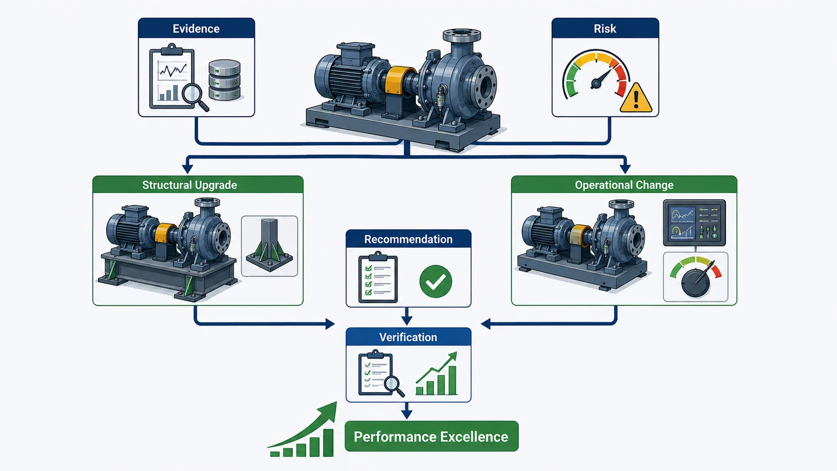
A useful decision framework is:
Evidence → Problem → Risk → Root Cause → Options → Evaluation → Recommendation → Approval → Implementation → Verification → Monitoring
This sequence creates a controlled connection between engineering analysis and operational improvement.
Strategic Recommendation Matrix
| Engineering Issue | Evidence | Potential Recommendation | Expected Outcome | Verification Method |
|---|---|---|---|---|
| Excessive vibration | Increasing vibration trend | Support or alignment improvement | Reduced vibration | Vibration monitoring |
| Repeated bearing failures | Maintenance history | Root-cause investigation and design/operational correction | Increased bearing life | MTBF comparison |
| Structural cracking | Inspection findings | Engineering redesign or controlled repair | Improved integrity | Inspection and testing |
| High operating temperature | Trend data | Cooling or operating optimisation | Reduced temperature | Temperature monitoring |
| Excessive downtime | Failure records | Reliability improvement programme | Increased availability | Availability analysis |
| Repeated leakage | Inspection records | Seal or connection improvement | Reduced leakage | Leak testing |
| Excessive loading | Operational data | Operating-envelope control | Reduced degradation | Load monitoring |
| Poor maintenance effectiveness | Audit and failure data | Revised maintenance strategy | Reduced repeat failures | Failure trend review |
Management-Level Recommendations
Senior management requires recommendations that clearly communicate:
- Engineering problem.
- Business consequence.
- Safety consequence.
- Required investment.
- Implementation timeframe.
- Expected benefit.
- Risk reduction.
- Performance target.
Technical complexity should not prevent decision-makers from understanding the importance of the recommendation.
Prioritising Recommendations
Where several improvements are identified, prioritisation may consider:
- Safety significance.
- Mechanical integrity.
- Equipment criticality.
- Failure probability.
- Production impact.
- Regulatory significance.
- Implementation complexity.
- Cost.
- Expected benefit.
High-risk issues should generally receive greater priority than low-consequence improvements.
Continuous Improvement
Strategic engineering recommendations should become part of a continuous improvement cycle:
Assess → Recommend → Approve → Implement → Verify → Measure → Review → Improve
This prevents improvements from becoming isolated projects.
Case Study: Long-Term Performance Improvement of a Critical Mechanical System
Background
A manufacturing facility operates a critical rotating mechanical system that has experienced recurring vibration, bearing failures, and production interruptions.
Historical records show increasing maintenance costs over several years.
Initial Assessment
The engineering team reviews:
- Operating hours.
- Vibration trends.
- Maintenance records.
- Failure frequency.
- Alignment history.
- Structural inspection findings.
- Production impact.
The analysis identifies a recurring relationship between structural movement and mechanical alignment.
Strategic Options
Three options are developed:
- Continue existing maintenance practices.
- Increase inspection frequency.
- Implement structural and operational improvements.
The first option has low immediate cost but does not address the underlying problem.
The second option improves detection but may not prevent recurrence.
The third option requires greater initial investment but has the potential to improve long-term reliability.
Recommended Strategy
The engineering team recommends:
- Structural support improvement.
- Alignment control.
- Enhanced vibration monitoring.
- Revised maintenance requirements.
- Defined performance targets.
- Post-modification verification.
Implementation
The change is planned during a controlled shutdown.
Engineering documentation is reviewed and approved before implementation.
Inspection and testing requirements are established.
Verification
After commissioning, performance is monitored.
The organisation compares:
- Vibration.
- Bearing temperature.
- Alignment.
- Failure frequency.
- Downtime.
- Maintenance cost.
Outcome
The improvement produces more stable operating performance and reduces repeated maintenance intervention.
The case demonstrates the importance of addressing the system-level causes of poor reliability rather than repeatedly treating individual component failures.
Conclusion
Producing strategic engineering recommendations is a critical part of transforming mechanical inspection, testing, reliability, and performance data into long-term operational improvement. Effective recommendations should be based on verified evidence and should clearly connect the identified engineering problem with its consequences, root causes, proposed solution, implementation requirements, expected benefits, and verification method. Structural upgrades may be necessary where mechanical integrity, support conditions, capacity, stiffness, fatigue resistance, or physical deterioration are responsible for poor performance, while operational changes may provide effective control where loading, speed, process conditions, start-up practices, or maintenance activities are contributing to deterioration.
A high-quality recommendation also considers lifecycle cost, equipment criticality, safety, maintainability, production continuity, quality assurance, regulatory requirements, and resource availability. Significant modifications should be managed through controlled engineering change processes, supported by appropriate design review, inspection, testing, documentation, and performance verification. The objective is not simply to install a stronger component or change an operating procedure, but to achieve a measurable and sustainable improvement in mechanical system performance.
Long-term performance excellence is achieved when recommendations become part of a continuous engineering improvement cycle. By combining reliability data, inspection findings, operational experience, historical maintenance records, risk assessment, and engineering judgement, organisations can prioritise investments that reduce failure risk, extend asset life, improve availability, strengthen mechanical integrity, and control lifecycle costs. A strategic approach therefore enables mechanical engineering teams to move from reactive problem-solving towards proactive asset performance management, creating safer, more reliable, efficient, and resilient mechanical operations.