
Lesson 4: Implement corrective measures to address quality deficiencies in mechanical systems.
Corrective measures are a fundamental part of effective mechanical QA/QC, ensuring that identified quality deficiencies are properly investigated, controlled, and resolved before they affect equipment performance, reliability, safety, or compliance. Mechanical quality deficiencies may result from dimensional inaccuracies, material defects, fabrication errors, incorrect assembly, equipment deterioration, inadequate maintenance, or deviations from approved engineering drawings, specifications, codes, and standards. Effective corrective action therefore involves more than repairing a visible defect; it requires identifying the problem, assessing its significance, determining the appropriate response, and confirming that the deficiency has been effectively resolved.
This lesson, “Implement Corrective Measures to Address Quality Deficiencies in Mechanical Systems,” examines a systematic approach to managing mechanical quality problems from identification through resolution and verification. It explores the use of inspection findings, measurement results, test data, non-conformance records, engineering documentation, and risk assessments to determine suitable corrective measures. Key areas include root cause analysis, repair and rework decisions, technical verification, quality control, documentation, traceability, and prevention of recurrence. These practices help ensure that corrective actions are technically appropriate, proportionate to the identified risk, and aligned with relevant engineering requirements.
Effective corrective action also supports mechanical system integrity, reliability, and continual improvement. Whether addressing a defective shaft, bearing wear, dimensional non-conformity, alignment problem, fabrication defect, pressure-system issue, or equipment performance failure, corrective decisions should consider safety, engineering tolerances, operational requirements, quality standards, downtime, cost, and long-term asset performance. By analysing recurring deficiencies and verifying the effectiveness of corrective measures, organisations can reduce repeat failures, strengthen QA/QC processes, improve maintenance outcomes, and support more reliable mechanical systems.
1: Design Realistic, Immediate Engineering Solutions and Rework Plans to Fix Validated Quality Deficiencies in Broken or Weak Mechanical Assemblies
Mechanical assemblies are expected to perform safely, reliably, and consistently under defined operating conditions. When inspection, testing, measurement, or operational evidence confirms that an assembly is defective, damaged, weak, or outside specified requirements, the engineering response must be practical, technically justified, and sufficiently controlled to restore the required level of quality. In mechanical QA/QC, a corrective solution should never be based solely on convenience or visual appearance. The proposed repair or rework must address the validated deficiency while considering design intent, material properties, loading conditions, dimensional tolerances, operating environment, safety requirements, maintainability, and future reliability.
Designing an immediate engineering solution involves translating an inspection finding into a controlled technical response. This may include repair, rework, replacement, adjustment, alignment, machining, strengthening, component substitution, controlled welding, surface restoration, fastening correction, lubrication correction, or other approved engineering intervention. The appropriate response depends on the nature and severity of the defect. A minor dimensional deviation may require controlled machining or adjustment, whereas a cracked load-bearing component may require complete replacement or an engineered repair supported by technical assessment.
For mechanical QA/QC professionals, the central principle is that corrective action must restore conformity rather than merely remove the visible symptom. A successful rework plan therefore connects the validated defect with its root cause, required engineering condition, corrective method, inspection requirements, acceptance criteria, responsible personnel, resources, and final verification. This creates a traceable process from defect identification to completed corrective action and provides objective evidence that the mechanical assembly is suitable for its intended service.
Understanding Validated Quality Deficiencies
A validated quality deficiency is a confirmed condition in which a mechanical component, assembly, process, or result does not satisfy an applicable requirement. Validation normally requires objective evidence rather than assumption. Evidence may originate from dimensional inspection, non-destructive testing, functional testing, material documentation, visual examination, vibration analysis, pressure testing, alignment checks, maintenance records, or comparison against approved engineering documentation.
A deficiency should be clearly defined before a corrective measure is selected. Engineers and QA/QC personnel should distinguish between an observed symptom and the actual quality problem. For example, excessive vibration may be the observable symptom, while the underlying deficiency could be shaft misalignment, bearing damage, imbalance, loose foundations, coupling problems, or inappropriate operating conditions.
Typical validated mechanical quality deficiencies include:
- Dimensional measurements outside tolerance
- Excessive shaft runout
- Incorrect component alignment
- Bearing damage or abnormal wear
- Cracks in load-bearing components
- Corrosion affecting section thickness
- Incorrect assembly clearances
- Damaged threads or fasteners
- Improper torque application
- Weld discontinuities or unacceptable weld defects
- Surface damage affecting sealing or fit
- Gear tooth damage or incorrect engagement
- Excessive leakage from mechanical joints
- Distortion following fabrication or welding
- Incorrect material or component identification
- Improper lubrication or contamination
- Deformation caused by excessive loading
- Inadequate support or foundation conditions
The confirmed deficiency should be recorded using appropriate QA/QC documentation before repair or rework begins. This provides a controlled starting point for the engineering decision.
Key Principles for Immediate Engineering Solutions
An immediate engineering solution is not necessarily a permanent solution. In many operational environments, an organisation may need to restore safe functionality quickly while a more comprehensive engineering investigation or permanent replacement is being developed. Immediate corrective action must therefore be controlled carefully.
The following principles should guide the response:
- Protect personnel before protecting production.
- Confirm the defect before selecting the repair.
- Understand the intended design function.
- Determine whether the defect affects safety or structural integrity.
- Prevent further damage before corrective work begins.
- Use technically suitable materials and processes.
- Maintain dimensional and geometric requirements.
- Follow approved engineering procedures.
- Define inspection and acceptance criteria in advance.
- Record every significant corrective activity.
- Verify the repaired assembly before returning it to service.
- Escalate safety-critical defects to appropriate engineering authority.
- Consider whether the same defect could exist elsewhere.
A fast solution is only an effective solution when it remains technically defensible and controlled.
From Defect Identification to Corrective Action
The corrective process should follow a logical sequence. The first stage is to understand exactly what has failed or deviated. The second is to assess the consequence of the deficiency. The third is to determine the technically appropriate corrective option. The fourth is to plan the work and controls. The fifth is to implement the repair or rework. The final stage is verification and release.
A practical corrective action sequence is:
- Identify the validated deficiency.
- Confirm the affected component or assembly.
- Review drawings and specifications.
- Establish the required condition.
- Assess operational and safety implications.
- Determine the probable root cause.
- Develop possible corrective options.
- Evaluate repair, rework, replacement, or acceptance alternatives.
- Select the technically appropriate solution.
- Develop a controlled rework plan.
- Obtain required technical approval.
- Prepare tools, materials, personnel, and equipment.
- Isolate and control the defective assembly.
- Complete the corrective work.
- Perform required inspections and tests.
- Compare results against acceptance criteria.
- Document the completed action.
- Obtain appropriate release or approval.
- Monitor performance after return to service.
-
Capture lessons for recurrence prevention.

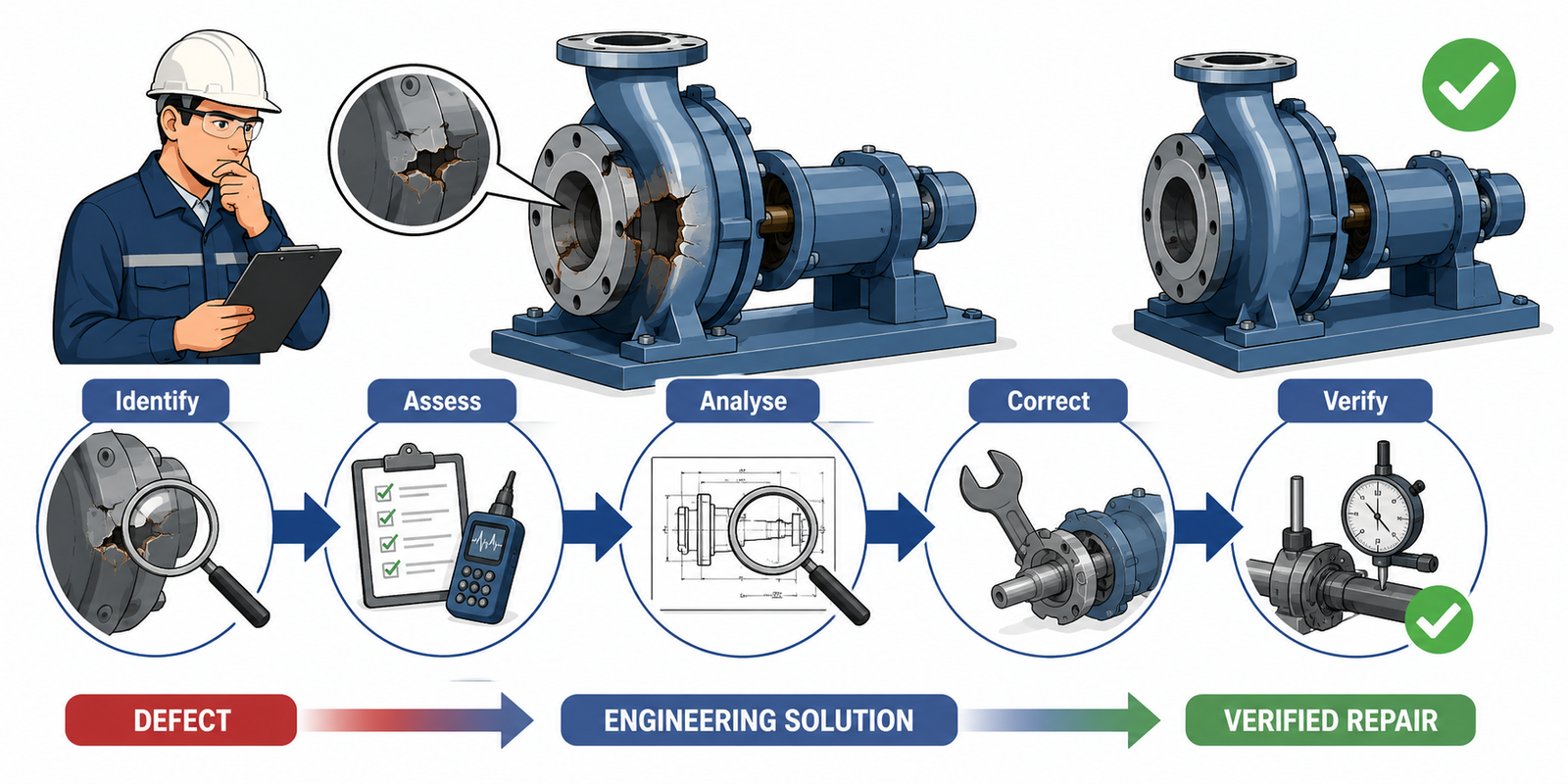
Table: Corrective Engineering Response to Mechanical Quality Deficiencies
| Deficiency | Engineering Response | Key Control | Verification Method |
|---|---|---|---|
| Shaft misalignment | Realign coupling and supports | Alignment tolerance | Laser or dial alignment |
| Excessive runout | Controlled machining or replacement | Dimensional tolerance | Dial indicator measurement |
| Bearing damage | Replace bearing and inspect shaft | Correct fit and lubrication | Clearance and functional test |
| Damaged thread | Rework or approved insert | Thread specification | Thread gauge and inspection |
| Surface corrosion | Clean, assess, restore or replace | Remaining section thickness | Thickness measurement |
| Gear tooth damage | Replace or approved repair | Gear geometry | Visual and dimensional inspection |
| Weld defect | Controlled repair welding | Approved welding procedure | NDT and visual inspection |
| Excessive clearance | Adjustment, machining or replacement | Specified clearance | Feeler gauge or micrometer |
| Loose fasteners | Controlled tightening or replacement | Torque requirement | Torque verification |
| Housing distortion | Rework, machining or replacement | Alignment and geometry | Dimensional inspection |
Developing a Realistic Engineering Solution
Review the Design Intent
Before deciding how to repair a mechanical assembly, the engineering team should establish what the component was originally designed to do. Design intent provides the foundation for deciding whether a repair is technically acceptable.
Relevant information may include:
- Approved engineering drawings
- Assembly drawings
- Component specifications
- Material specifications
- Equipment datasheets
- Manufacturer requirements
- Design calculations
- Operating limits
- Dimensional tolerances
- Surface-finish requirements
- Fit and clearance requirements
- Pressure and temperature limits
- Load and speed requirements
- Maintenance instructions
- Previous inspection records
A repair that changes a component’s geometry, material, stiffness, mass, or connection method may alter its performance. Therefore, the proposed corrective measure must be assessed against the original functional requirements.
Assess the Extent of Damage
The visible defect may not represent the full extent of the problem. For example, a crack visible on the surface of a shaft may extend below the surface or into a highly stressed region. Similarly, bearing damage may have resulted from shaft misalignment or lubrication failure, meaning that simply replacing the bearing may not solve the underlying problem.
The assessment should establish:
- Defect location
- Defect size
- Defect depth
- Affected component
- Affected assembly
- Possible secondary damage
- Operating conditions
- Loading conditions
- Failure history
- Remaining serviceability
- Potential consequences of continued operation
Where necessary, additional inspection or testing should be completed before the corrective solution is finalised.
Determine the Corrective Option
Mechanical QA/QC decisions commonly involve four broad options: repair, rework, replacement, or controlled acceptance. The choice should be based on engineering evidence rather than production pressure.
Repair may be suitable when the original component can be restored without compromising its intended performance. Rework may be appropriate where material can be removed, dimensions adjusted, surfaces restored, or assembly conditions corrected. Replacement is normally preferred when the component has suffered severe damage, cannot be reliably restored, or when repair would introduce unacceptable uncertainty.
A controlled acceptance or concession may sometimes be considered where a deviation does not adversely affect function, safety, integrity, or regulatory compliance and has been formally evaluated by the appropriate authority. Such a decision should never be used simply to avoid corrective work.
Evaluate Repair Versus Replacement
A repair decision should consider technical, operational, financial, and quality factors simultaneously.
Important considerations include:
- Severity of the defect
- Component criticality
- Remaining structural capacity
- Material condition
- Repairability
- Availability of replacement parts
- Expected repair life
- Cost of repair
- Cost of replacement
- Production downtime
- Safety consequences
- Inspection requirements
- Reliability after repair
- Manufacturer limitations
- Future maintenance requirements
For example, replacing a damaged bearing may be straightforward, but if the shaft journal is worn beyond its specified tolerance, installing a new bearing alone would not provide a reliable solution. The shaft condition must also be corrected or the shaft replaced.
Designing a Controlled Rework Plan
Define the Scope of Work
A rework plan should clearly identify what is being corrected and what is excluded from the activity. Ambiguous work scopes can result in incomplete repairs or inconsistent results.
A good scope should identify:
- Equipment identification
- Component identification
- Defect reference
- Location of defect
- Required corrective action
- Applicable drawings
- Required materials
- Required tools
- Inspection points
- Testing requirements
- Acceptance criteria
- Responsible personnel
- Approval requirements
- Completion documentation
The scope should be sufficiently detailed to control the work without introducing unnecessary complexity.
Establish the Work Sequence
The order of corrective activities can influence the quality of the final result. For example, alignment should normally be verified after relevant components have been correctly installed and secured. Similarly, dimensional verification should occur after machining but before final assembly.
A typical rework sequence could include:
- Isolate equipment.
- Confirm component identification.
- Record existing condition.
- Remove damaged component where required.
- Clean and prepare the affected area.
- Perform detailed inspection.
- Complete approved repair or rework.
- Restore required dimensions.
- Conduct intermediate inspection.
- Reassemble components.
- Verify alignment and clearances.
- Complete functional testing.
- Record final results.
- Release the equipment.
Define Acceptance Criteria Before Work Begins
Acceptance criteria provide an objective basis for determining whether corrective work has succeeded. Without predefined criteria, there is a risk that personnel will judge the repair subjectively.
Acceptance criteria may include:
- Dimensional tolerance
- Geometric tolerance
- Surface finish
- Shaft runout
- Alignment tolerance
- Bearing clearance
- Fastener torque
- Pressure-test result
- Leakage limit
- Vibration level
- Temperature range
- Functional performance
- NDT acceptance requirements
The criteria should be taken from the appropriate engineering specification, approved drawing, manufacturer requirement, applicable standard, or authorised engineering assessment.
Root Cause and Corrective Action
Why Root Cause Matters
Correcting the immediate defect without addressing its cause can result in recurrence. Root cause analysis should therefore form part of the corrective process, particularly for repeated, safety-critical, or high-consequence failures.
For example, repeated bearing failures may be associated with:
- Misalignment
- Poor lubrication
- Contamination
- Excessive loading
- Incorrect installation
- Incorrect bearing selection
- Shaft damage
- Foundation movement
- Operating conditions outside design limits
Replacing the bearing without investigating these factors may restore the equipment temporarily but does not provide an effective long-term corrective action.
Practical Root Cause Questions
Engineering teams can ask:
- What failed?
- Where did it fail?
- When did it fail?
- What conditions existed during failure?
- Has the problem occurred previously?
- What changed before the failure?
- Was the component correctly specified?
- Was the component correctly manufactured?
- Was assembly completed correctly?
- Was maintenance performed correctly?
- Were operating limits exceeded?
- Could another component have caused the failure?
These questions help move the investigation from symptom correction toward systemic improvement.
Managing Repair and Rework Risks
Corrective work can introduce new risks if it is poorly planned. A repair may alter component properties, create new stress concentrations, introduce dimensional errors, or compromise protective surfaces.
Before work begins, the engineering team should evaluate:
- Mechanical loading
- Thermal effects
- Pressure conditions
- Rotational speed
- Material compatibility
- Welding effects
- Machining allowances
- Heat treatment requirements
- Surface condition
- Alignment
- Access limitations
- Contamination risks
- Temporary support requirements
- Personnel safety
- Post-repair inspection requirements
Particular attention should be given to critical components. A repair to a non-critical cover may have significantly different consequences from a repair to a rotating shaft, pressure boundary, lifting component, or primary structural connection.
Selecting Materials and Repair Methods
Material Compatibility
The replacement or repair material must be suitable for the service environment and compatible with the original component where relevant. Material selection can influence strength, hardness, wear resistance, corrosion resistance, thermal behaviour, and fatigue performance.
Before selecting a material, consider:
- Material grade
- Mechanical properties
- Operating temperature
- Corrosion environment
- Wear conditions
- Compatibility with mating components
- Manufacturing requirements
- Heat treatment
- Welding requirements
- Surface treatment
- Availability and traceability
Material substitution should not be treated as a simple purchasing decision where the component is safety or performance critical.
Repair Method Selection
Different deficiencies require different corrective techniques. Examples include:
- Controlled machining for dimensional correction
- Shaft polishing for minor surface restoration
- Component replacement for severe damage
- Bearing replacement for confirmed bearing failure
- Alignment correction for misalignment
- Thread restoration for damaged threads
- Approved welding repair for suitable weldable components
- Surface treatment for specified corrosion protection
- Fastener replacement where integrity is compromised
- Controlled shimming for alignment correction
- Lubrication correction for maintenance-related deficiencies
The selected method should be appropriate to the component, material, defect, and service conditions.
Inspection and Verification During Rework
Quality control should not be limited to the final inspection. Intermediate inspection points are often essential because defects can become concealed after subsequent assembly stages.
Useful inspection hold points include:
- Initial condition inspection
- Material verification
- Preparation inspection
- Dimensional inspection
- Repair-process inspection
- Post-machining inspection
- Weld inspection
- Alignment inspection
- Assembly inspection
- Final functional testing
A staged inspection approach helps identify errors before they become more difficult or expensive to correct.
Documentation and Traceability
A properly controlled corrective action should create an auditable record. Documentation provides evidence that the deficiency was understood, the corrective method was approved, the work was completed correctly, and the repaired assembly met defined requirements.
Typical records include:
- Non-conformance report
- Inspection report
- Engineering assessment
- Repair procedure
- Rework instruction
- Material certificates
- Measurement records
- Test reports
- NDT reports
- Calibration records
- Photographic evidence
- Alignment records
- Torque records
- Final acceptance documentation
Traceability is particularly important for safety-critical mechanical components because future maintenance and engineering decisions may depend on the repair history.
Practical Example: Correcting a Pump Shaft Deficiency
Scenario
A centrifugal process pump experiences increasing vibration during operation. Inspection identifies excessive shaft runout. Further dimensional measurement confirms that the shaft journal is outside the specified tolerance, while the bearing also shows abnormal wear.
The initial temptation may be to replace the bearing because it is visibly damaged. However, the engineering assessment identifies the shaft condition as a contributing factor. Replacing the bearing alone could result in another premature failure.
Engineering Assessment
The QA/QC engineer reviews:
- Pump assembly drawing
- Shaft dimensional requirements
- Bearing specification
- Alignment requirements
- Operating speed
- Historical vibration readings
- Previous maintenance records
- Shaft inspection results
The evidence indicates that the shaft journal has exceeded the permissible dimensional condition and that the bearing damage is likely secondary.
Corrective Solution
The engineering team determines that the appropriate response is controlled shaft rework or replacement, depending on the remaining material allowance. If sufficient material remains for machining while retaining the required shaft dimensions and mechanical properties, controlled machining may be considered. If the dimensional reduction would compromise the design condition, replacement becomes the preferred solution.
The rework plan includes:
- Remove and identify the pump shaft.
- Record the existing dimensional condition.
- Inspect the shaft for additional damage.
- Confirm material identification.
- Establish machining limits.
- Machine the affected journal under controlled conditions.
- Verify final dimensions.
- Check shaft runout.
- Inspect the bearing seat.
- Install the correct bearing.
- Verify coupling alignment.
- Complete controlled assembly.
- Conduct operational testing.
- Measure vibration.
- Compare results against acceptance criteria.
- Document the completed corrective action.
Verification
The repair is not considered complete merely because the shaft has been machined. Final verification should demonstrate that the complete assembly performs correctly.
Verification may include:
- Shaft diameter measurement
- Shaft runout measurement
- Bearing clearance verification
- Coupling alignment
- Fastener torque verification
- Lubrication confirmation
- Rotation check
- Vibration monitoring
- Temperature monitoring
- Leakage inspection
- Functional performance testing
If the final measurements and operational results meet the defined acceptance criteria, the pump can proceed through the appropriate release process.
Lessons from the Case
This example demonstrates why effective mechanical corrective action must consider the complete assembly rather than an isolated component. The bearing was damaged, but the underlying shaft condition had to be addressed to prevent recurrence.
The case also demonstrates several important QA/QC principles:
- Confirm the defect with objective evidence.
- Investigate related components.
- Identify the underlying cause.
- Compare conditions against engineering requirements.
- Select repair or replacement based on technical evidence.
- Define acceptance criteria before corrective work.
- Verify the entire assembly after repair.
- Record the corrective action for future traceability.
Key Benefits of Effective Corrective Measures
Well-designed corrective measures provide benefits that extend beyond restoring a single component.
Improved Mechanical Reliability
Corrective action restores equipment to an appropriate technical condition and reduces the likelihood of premature failure.
Improved Asset Integrity
Properly controlled repairs protect critical mechanical components from progressive deterioration and help maintain their intended operating capability.
Reduced Repeat Defects
Root cause investigation and corrective action reduce the likelihood that the same quality deficiency will occur again.
Better Maintenance Performance
Accurate corrective records help maintenance teams understand equipment history and make better future maintenance decisions.
Reduced Downtime
A well-planned rework strategy can minimise unnecessary disassembly, repeated repairs, and extended equipment outages.
Improved Cost Control
Although a technically appropriate repair may require an initial investment, preventing repeat failure can significantly reduce long-term costs associated with emergency repairs, production losses, replacement components, and secondary damage.
Stronger Quality Assurance
Documented corrective action provides objective evidence that identified deficiencies have been controlled and verified.
Better Decision-Making
Engineering decisions become more consistent when they are based on drawings, measurements, inspection results, risk assessments, and defined acceptance criteria rather than assumptions.
Practical QA/QC Decision Framework
When deciding how to correct a mechanical quality deficiency, the following questions provide a useful engineering decision structure:
- What exactly has failed or deviated?
- Is the deficiency confirmed by objective evidence?
- What function does the affected component perform?
- Is the component safety critical?
- What are the operating loads and conditions?
- What is the extent of the damage?
- What caused the deficiency?
- Can the component be safely repaired?
- Would repair restore the required design condition?
- Is replacement more technically appropriate?
- What materials and processes are required?
- What inspection points are necessary?
- What acceptance criteria apply?
- Who must approve the corrective method?
- How will the repaired assembly be tested?
- What records must be retained?
- Could the same problem exist elsewhere?
This framework supports a balanced approach that considers safety, quality, technical performance, cost, and operational continuity.
Engineering Considerations for Immediate Versus Permanent Solutions
In operational environments, an immediate corrective measure may sometimes be required to control an emerging problem while a permanent engineering solution is developed. However, temporary measures must be clearly distinguished from permanent repairs.
An immediate solution may involve:
- Temporary equipment isolation
- Controlled operating restrictions
- Temporary component replacement
- Temporary monitoring
- Increased inspection frequency
- Controlled load reduction
- Temporary support
- Short-term adjustment
Such measures should only be used where technically justified and appropriately authorised. A temporary solution should have clear conditions for use, monitoring requirements, limitations, and transition arrangements toward the permanent corrective action.
The key principle is that temporary control should reduce risk rather than create an uncontrolled dependency on an interim arrangement.
Integrating Corrective Action with Mechanical QA/QC
Corrective measures should form part of a wider quality management process. Inspection identifies the deficiency, QA/QC establishes objective evidence, engineering evaluates the technical implications, maintenance or production teams implement the approved solution, and verification confirms conformity.
This creates a closed-loop quality process:
- Inspection identifies the condition.
- Measurement confirms the deficiency.
- QA/QC records the non-conformance.
- Engineering evaluates the technical significance.
- Root cause analysis identifies contributing factors.
- Corrective planning establishes the required response.
- Rework or repair restores the component.
- Inspection verifies the work.
- Testing confirms performance.
- QA/QC documents closure.
- Management reviews recurring trends.
- Lessons learned improve future processes.
This closed-loop approach is particularly important in complex mechanical systems where one component failure can affect other connected components.
Case Study: Corrective Rework of a Gearbox Assembly
Background
A gearbox used in an industrial production line begins showing abnormal noise and increasing temperature. Routine inspection identifies surface damage on one gear and abnormal bearing clearance. Historical maintenance records show that the gearbox experienced similar symptoms several months earlier.
Initial Investigation
The QA/QC engineer reviews the inspection records and compares the measured gear condition and bearing clearance with the applicable engineering requirements. The inspection also identifies evidence of uneven gear contact.
Instead of replacing only the damaged gear, the engineering team considers the complete transmission system. Shaft alignment, bearing seating, lubrication condition, gear engagement, housing condition, and operating load are reviewed.
Corrective Plan
The proposed corrective plan includes:
- Removing the affected gearbox from service.
- Inspecting all related gears.
- Checking shaft alignment.
- Measuring bearing clearances.
- Inspecting bearing seats.
- Checking housing condition.
- Verifying lubrication condition.
- Replacing damaged components.
- Correcting alignment where required.
- Replacing unsuitable bearings.
- Restoring correct lubrication.
- Checking gear contact pattern.
- Completing final dimensional inspection.
- Conducting controlled operational testing.
Verification
After reassembly, the gearbox is tested under controlled operating conditions. Temperature and vibration are monitored, while abnormal noise is checked. The measured results are compared against established operating and acceptance criteria.
The gearbox is only released after the corrective work and verification activities demonstrate that the assembly has returned to an acceptable operating condition.
Long-Term Improvement
The repeated nature of the defect indicates that the organisation should investigate why the previous corrective action did not prevent recurrence. The review may identify weaknesses in alignment control, lubrication management, inspection frequency, installation procedures, or operator practices.
The corrective action therefore extends beyond the gearbox itself and becomes an opportunity to improve the wider maintenance and QA/QC process.
Good Engineering Practice in Corrective Rework
Effective corrective measures should demonstrate several characteristics:
- Technically justified
- Based on objective evidence
- Proportionate to risk
- Consistent with design requirements
- Clearly documented
- Properly authorised
- Traceable
- Inspectable
- Testable
- Verifiable
- Suitable for intended service
- Focused on recurrence prevention
A technically successful repair is one that restores the required condition while maintaining confidence in future performance.
Conclusion
Designing realistic immediate engineering solutions and rework plans is a central responsibility within mechanical QA/QC because defective assemblies can affect equipment reliability, production continuity, asset integrity, and safety. An effective corrective response begins with objective validation of the deficiency and continues through design review, damage assessment, root cause analysis, selection of repair or replacement, controlled implementation, inspection, testing, documentation, and final verification. The process should always focus on restoring the required engineering condition rather than simply removing the visible symptom.
A strong corrective action system also creates a continuous improvement cycle. When engineering teams use inspection evidence, dimensional data, test results, maintenance history, risk assessment, and failure trends to develop corrective measures, they can reduce repeat defects and improve long-term mechanical performance. The essential engineering principle is to identify the real problem, select a technically defensible solution, control the rework process, verify the completed assembly, and capture the resulting knowledge so that future mechanical systems become safer, more reliable, and more maintainable.
2: Supervise the Execution of Corrective Maintenance Actions to Ensure Repaired Parts Are Restored to Full Operational Compliance Without Compromising Safety
Supervising corrective maintenance is a critical mechanical QA/QC responsibility because the technical quality of a repair depends not only on the selected corrective method but also on how accurately and safely that method is executed. A repair may be technically appropriate on paper but still fail to restore the mechanical system if incorrect materials, unsuitable tools, poor workmanship, inaccurate measurements, inadequate assembly procedures, or uncontrolled changes are introduced during execution. Effective supervision therefore provides a controlled link between the approved corrective action plan and the final operational condition of the repaired equipment.
Corrective maintenance supervision involves monitoring repair activities, confirming that approved procedures are followed, checking materials and component identification, verifying measurements, controlling workmanship, managing inspection hold points, and ensuring that safety and quality requirements remain effective throughout the work. It also requires communication between maintenance personnel, mechanical engineers, QA/QC inspectors, operations teams, contractors, and other technical specialists. The objective is not simply to complete the repair quickly, but to ensure that the repaired component or assembly is demonstrably fit for its intended purpose.
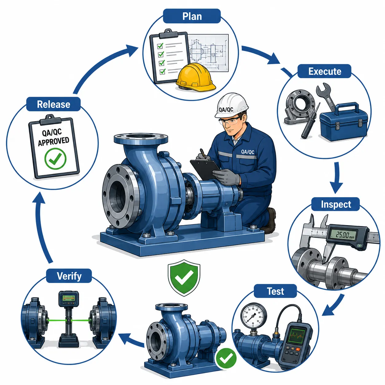
For mechanical QA/QC professionals, operational compliance means that repaired equipment satisfies its approved technical requirements, applicable acceptance criteria, safety controls, operating limits, inspection requirements, and functional performance expectations. The completed work should therefore provide objective evidence that the original deficiency has been corrected and that the corrective maintenance has not introduced new defects or unacceptable risks. A disciplined supervision process helps achieve this through the sequence of preparation, controlled execution, inspection, testing, verification, documentation, and formal release.
Understanding Corrective Maintenance Supervision
Corrective maintenance is undertaken after a defect, failure, deterioration, or non-conforming condition has been identified. It may involve repair, replacement, adjustment, restoration, machining, alignment, welding, component refurbishment, reassembly, or other approved intervention.
Supervision ensures that the corrective maintenance activity is carried out in accordance with the approved technical requirements rather than relying on informal judgement during the repair.
A supervisor or QA/QC professional should continuously consider three connected objectives:
- Safety must be maintained throughout the intervention.
- Quality requirements must be achieved during the work.
- Operational compliance must be demonstrated before release.
These objectives should not be treated separately. For example, a rushed repair may reduce downtime but increase the probability of incorrect assembly. Similarly, a technically accurate repair may still be unacceptable if isolation, access, lifting, pressure release, or other safety controls were inadequate.
Key Concepts
| Concept | Definition | Practical Application |
|---|---|---|
| Corrective Maintenance | Maintenance performed to restore equipment after a confirmed defect or failure | Repairing a damaged shaft or replacing a failed bearing |
| Work Control | System used to control how maintenance activities are planned and executed | Approved work instruction and permit controls |
| Hold Point | A defined stage where work must stop until inspection or approval is completed | Inspection before final assembly |
| Acceptance Criteria | Defined requirements used to determine whether completed work is acceptable | Shaft runout within specified tolerance |
| Operational Compliance | Demonstrated conformity with required technical and operating conditions | Equipment passes functional and performance checks |
| Quality Verification | Evidence confirming that corrective work meets specified requirements | Measurement, inspection, testing and documented results |
| Reinstatement | Controlled return of repaired equipment to service | Final checks followed by authorised release |
| Traceability | Ability to link repair activities to components, records and requirements | Component serial number linked to inspection records |
Preparing for Corrective Maintenance Execution
Review the Approved Corrective Action
Before maintenance begins, the responsible personnel should understand exactly what has been authorised. The approved corrective action should identify the defect, required repair method, applicable drawings, materials, inspection requirements, acceptance criteria, and responsibilities.
The supervisor should confirm:
- Correct equipment identification
- Correct component identification
- Approved repair method
- Current engineering documentation
- Applicable drawings and specifications
- Required tools and equipment
- Approved materials
- Competent personnel
- Required inspection stages
- Testing requirements
- Safety controls
- Acceptance criteria
- Required records
- Approval responsibilities
This review prevents a common quality problem: beginning physical work before the technical requirements are sufficiently understood.
Conduct a Pre-Work Review
A pre-work review provides an opportunity to identify problems before they affect the repair. It should bring together the relevant personnel and establish a common understanding of the work.
The review may cover:
- Scope of corrective maintenance
- Known defect condition
- Work sequence
- Technical risks
- Safety hazards
- Quality risks
- Inspection points
- Testing arrangements
- Required resources
- Expected completion condition
- Communication arrangements
- Contingency arrangements
For complex equipment, a pre-work briefing can significantly reduce misunderstanding between maintenance, engineering, QA/QC, and operations teams.
Confirming Component and Material Control
Component Identification
Incorrect component identification can result in the wrong part being repaired, replaced, or installed. This is particularly important where similar components exist within a facility.
Supervision should confirm:
- Equipment tag number
- Component identification
- Serial number where applicable
- Drawing reference
- Part number
- Orientation
- Installation location
- Removal and replacement records
Material Verification
Materials used during corrective maintenance should meet the approved requirements. This can include replacement bearings, fasteners, shafts, seals, welding consumables, gaskets, lubricants, coatings, or other materials.
The QA/QC supervisor should verify:
- Material grade
- Manufacturer information
- Certificate requirements
- Batch or heat number
- Dimensions
- Compatibility
- Storage condition
- Expiry date where applicable
- Traceability requirements
- Correct quantity
Substituting a material simply because it is readily available can create significant reliability or safety problems if the substitution has not been technically assessed and approved.
Supervising the Actual Repair
Control the Work Sequence
Corrective maintenance should follow an established sequence. The sequence should reflect the engineering requirements and avoid introducing new damage.
For a mechanical assembly, this could involve:
- Isolate equipment.
- Confirm safe work condition.
- Verify component identification.
- Record existing condition.
- Remove damaged component.
- Inspect surrounding components.
- Prepare repair area.
- Perform approved repair.
- Conduct intermediate inspection.
- Complete dimensional verification.
- Reassemble components.
- Verify clearances.
- Check alignment.
- Apply specified torque.
- Complete lubrication.
- Conduct final inspection.
- Perform functional testing.
- Record results.
- Obtain release approval.
The supervisor should ensure that deviations from the planned sequence are evaluated rather than accepted informally.
Monitor Workmanship
Workmanship can directly affect mechanical reliability. Even where the correct materials and procedures are used, poor execution can result in premature failure.
Supervision should consider:
- Correct tool use
- Proper component handling
- Cleanliness
- Surface preparation
- Correct assembly orientation
- Correct fastener installation
- Torque control
- Alignment
- Fit and clearance
- Lubrication
- Sealing
- Welding quality where applicable
- Protection of finished surfaces
A high-quality repair should not leave secondary damage, contamination, distortion, or assembly defects.
Managing Safety During Corrective Maintenance
Safety must remain an active supervision responsibility throughout corrective maintenance. The fact that equipment has been taken out of service does not automatically make the work safe.
Potential hazards can include:
- Stored mechanical energy
- Electrical energy
- Hydraulic pressure
- Pneumatic pressure
- Steam or thermal energy
- Hot surfaces
- Rotating components
- Suspended loads
- Sharp edges
- Chemical exposure
- Confined spaces
- Unexpected equipment movement
- Residual pressure
- Hazardous substances
The supervisor should confirm that appropriate controls remain in place throughout the activity.
Essential Safety Controls
Depending on the equipment and work environment, controls may include:
- Equipment isolation
- Lockout/tagout
- Permit-to-work controls
- Depressurisation
- Drainage
- Electrical isolation
- Mechanical blocking
- Controlled lifting
- Barricading
- Appropriate PPE
- Gas testing where applicable
- Safe access
- Tool control
- Housekeeping
- Emergency arrangements
Safety controls should be reassessed if the work scope changes or unexpected conditions are discovered.
Quality Hold Points and Inspection Stages
Importance of Hold Points
A hold point prevents maintenance work from progressing beyond a critical stage until the required inspection or approval has been completed. This is particularly important when subsequent work would conceal the quality of the preceding activity.
Examples include:
- Inspection before closing a gearbox housing
- Dimensional verification before installing a bearing
- Weld inspection before applying protective coating
- Alignment verification before final coupling installation
- Pressure testing before insulation
- Electrical continuity checks before enclosure closure
- Final inspection before equipment reinstatement
Hold points should be clearly identified in the corrective maintenance plan.
Witness and Review Points
Not every activity requires a formal hold point. Some may be designated as witness or review points, depending on risk and quality requirements.
The supervision strategy should therefore distinguish between:
- Hold points
- Witness points
- Surveillance activities
- Routine inspections
- Final acceptance inspections
This helps allocate QA/QC resources effectively while maintaining control over critical activities.
Dimensional and Geometric Verification
Mechanical repairs frequently depend on precise dimensions. A repaired part may appear visually acceptable while remaining outside engineering requirements.
Important measurements may include:
- Shaft diameter
- Bore diameter
- Bearing clearance
- Shaft runout
- Flatness
- Parallelism
- Perpendicularity
- Concentricity
- Gear backlash
- Coupling alignment
- Surface finish
- Component thickness
- Thread dimensions
Appropriate calibrated instruments should be used, and measurement results should be recorded against defined acceptance criteria.
Measurement Control
Supervisors should verify:
- Instrument suitability
- Calibration status
- Measurement range
- Measurement method
- Environmental conditions where relevant
- Measurement location
- Recorded result
- Acceptance limit
- Inspector identification
A measurement without a defined acceptance criterion has limited value because the result cannot be objectively judged.
Supervising Assembly and Reassembly
Correct Assembly Matters
A repaired component can still fail if it is incorrectly installed. Reassembly should therefore receive the same level of quality attention as the repair itself.
Important checks include:
- Component orientation
- Correct mating surfaces
- Correct bearing installation
- Shaft positioning
- Seal installation
- Fastener selection
- Fastener sequence
- Torque requirements
- Clearances
- Lubrication
- Alignment
- Coupling installation
- Guards and protective devices
Where manufacturer-specific assembly requirements exist, they should be incorporated into the corrective maintenance process.
Torque Control
Incorrect fastener torque can create either insufficient clamping or excessive loading. Both conditions can compromise equipment reliability.
Controlled torque practices should consider:
- Correct fastener specification
- Required torque value
- Torque sequence
- Tool calibration
- Lubrication condition
- Thread condition
- Access limitations
- Final verification
Torque records may be required for critical mechanical connections.
Alignment and Fit Verification
Alignment problems are a common contributor to mechanical failures. Corrective maintenance should therefore verify alignment where the repaired component interacts with rotating or connected equipment.
Typical applications include:
- Pump and motor alignment
- Gearbox alignment
- Coupling alignment
- Shaft alignment
- Bearing housing alignment
- Pulley alignment
- Drive system alignment
Misalignment can result in:
- Increased vibration
- Bearing wear
- Seal failure
- Coupling damage
- Shaft fatigue
- Increased energy consumption
- Excessive temperature
- Premature equipment failure
Alignment should be verified using suitable methods and against specified tolerances.
Functional Testing After Repair

Why Functional Testing Is Essential
A repaired component may satisfy dimensional requirements but still fail during operation. Functional testing therefore provides an additional layer of verification.
Testing should be based on the equipment’s intended function and applicable acceptance requirements.
Depending on the system, testing may include:
- No-load rotation
- Controlled start-up
- Pressure testing
- Leak testing
- Vibration monitoring
- Temperature monitoring
- Speed verification
- Flow verification
- Noise assessment
- Load testing
- Performance testing
- Electrical checks for electrically driven equipment
The test should be conducted under controlled conditions, with appropriate monitoring and predefined acceptance criteria.
Controlled Start-Up
For critical equipment, immediate operation at full load may not be appropriate. A staged start-up can allow abnormal conditions to be detected before they escalate.
A controlled start-up may involve:
- Confirm final inspection.
- Confirm guards and protections.
- Confirm lubrication.
- Confirm alignment.
- Start under controlled conditions.
- Monitor vibration.
- Monitor temperature.
- Monitor pressure or flow.
- Check for leakage or abnormal noise.
- Increase operating conditions progressively.
- Compare results against acceptance criteria.
- Stop and investigate if abnormal conditions occur.
Managing Unexpected Conditions
Corrective maintenance rarely proceeds exactly as expected in every situation. Hidden damage, seized components, unexpected corrosion, incorrect previous repairs, or dimensional discrepancies may be discovered during execution.
When unexpected conditions arise, the supervisor should not allow personnel to improvise uncontrolled solutions.
The response should generally involve:
- Stop affected work.
- Protect the equipment and personnel.
- Record the unexpected condition.
- Inform responsible engineering personnel.
- Assess the technical implication.
- Determine whether the approved method remains suitable.
- Revise the corrective plan where necessary.
- Obtain appropriate approval.
- Resume work under the revised controls.
This prevents uncontrolled modifications from becoming embedded in the repaired assembly.
Non-Conformance During Corrective Maintenance
A second defect may sometimes be discovered during corrective work. For example, removal of a damaged bearing may reveal a damaged bearing seat.
This should be treated as a new quality finding requiring evaluation.
The process may involve:
- Recording the additional deficiency
- Assessing its significance
- Determining whether it affects the original repair
- Updating the repair scope
- Conducting engineering assessment
- Revising inspection requirements
- Obtaining additional approval
- Completing the additional corrective work
- Re-verifying the complete assembly
The discovery of additional damage should not automatically be treated as a minor maintenance issue.
Case Study: Supervising Corrective Maintenance on a Centrifugal Pump
Background
A centrifugal pump supplying process water develops increasing vibration and elevated bearing temperature. Inspection confirms that the bearing is worn and that shaft alignment is outside the specified tolerance.
The maintenance team proposes replacing the bearing and realigning the pump.
Supervision Strategy
Before work begins, the QA/QC supervisor reviews:
- Pump identification
- Approved repair scope
- Shaft and bearing requirements
- Alignment tolerances
- Replacement bearing documentation
- Calibration records
- Safety controls
- Inspection points
- Functional testing requirements
The supervisor confirms that the equipment is correctly isolated and that the replacement bearing matches the specified requirements.
Execution
The damaged bearing is removed and the shaft and bearing seat are inspected. Additional scoring is discovered on the shaft surface.
The supervisor stops the planned installation and records the finding. Engineering reviews the condition and determines that installing the new bearing without addressing the shaft damage could result in premature failure.
The corrective plan is therefore revised to include shaft restoration or replacement, subject to dimensional assessment.
Verification
After corrective work, the supervisor oversees:
- Shaft dimensional inspection
- Bearing fit verification
- Bearing installation
- Lubrication
- Coupling alignment
- Fastener torque checks
- Guard installation
- Rotation checks
- Controlled start-up
- Vibration monitoring
- Bearing temperature monitoring
The pump is returned to service only after the final results meet the defined acceptance requirements.
Case Study Lessons
The case demonstrates that effective supervision is not simply observing maintenance personnel. It involves active technical control.
Important lessons include:
- Follow the approved corrective plan.
- Verify replacement components.
- Inspect related components.
- Stop when unexpected damage is discovered.
- Escalate technical changes.
- Verify dimensions before assembly.
- Confirm alignment after reassembly.
- Test equipment before full operational release.
- Maintain complete documentation.
Practical Example: Gearbox Rework
A gearbox experiences abnormal noise and temperature after a maintenance intervention. Inspection reveals incorrect bearing clearance and poor gear alignment.
The supervisor reviews the previous maintenance records and identifies that the bearing replacement had been completed without a documented clearance verification.
The corrective maintenance plan is revised to include:
- Bearing removal
- Bearing seat inspection
- Clearance measurement
- Gear alignment inspection
- Lubrication verification
- Correct bearing installation
- Gear contact inspection
- Shaft alignment
- Housing closure inspection
- Functional testing
During reassembly, the QA/QC inspector verifies the measured clearance against the specified range before allowing the gearbox housing to be closed.
This illustrates the importance of inspection at the correct stage. If the housing had been closed before the clearance was verified, correcting the deficiency would have required additional disassembly and increased downtime.
Documentation of Corrective Maintenance
Required Evidence
A completed corrective maintenance activity should leave a clear quality record.
Documentation may include:
- Corrective maintenance work order
- Inspection reports
- Measurement sheets
- Material certificates
- Component identification records
- Calibration certificates
- Repair records
- Welding records
- NDT reports
- Alignment reports
- Torque records
- Test results
- Photographs
- NCR closure evidence
- Final acceptance records
Documentation should be clear enough to demonstrate what was done, why it was done, who completed it, what was inspected, what results were obtained, and who authorised release.
Traceability
Traceability allows future engineers and maintenance personnel to understand the history of the equipment.
A traceable record can link:
- Equipment
- Component
- Defect
- Corrective action
- Replacement material
- Inspection
- Test
- Acceptance
- Release
This becomes particularly valuable when investigating future failures or planning preventive maintenance.
Operational Compliance and Return to Service
Defining Operational Compliance
A repaired component should not be considered compliant simply because the physical repair is complete. Operational compliance requires evidence that the equipment can perform its intended function within defined limits.
This may involve confirming:
- Correct dimensions
- Correct assembly
- Correct alignment
- Correct lubrication
- Correct pressure
- Correct temperature
- Acceptable vibration
- Acceptable leakage
- Correct speed
- Required output
- Functional protection
- Required safety controls
Final Release Process
A controlled release process may include:
- Completion of corrective work.
- Final visual inspection.
- Dimensional verification.
- Assembly verification.
- Functional testing.
- Review of inspection records.
- Confirmation of outstanding issues.
- QA/QC acceptance.
- Engineering approval where required.
- Operations acceptance.
- Equipment reinstatement.
- Post-start monitoring.
The level of approval should reflect equipment criticality and organisational procedures.
Key Benefits of Effective Corrective Maintenance Supervision
Improved Safety
Active supervision helps prevent unsafe work practices, uncontrolled energy release, incorrect component installation, and premature equipment return to service.
Improved Quality
Inspection and verification throughout the repair process reduce the risk of hidden defects remaining in the completed assembly.
Improved Reliability
Properly supervised corrective maintenance helps ensure that the root problem is addressed rather than merely treating the visible symptom.
Reduced Repeat Failures
Effective verification and root cause evaluation help prevent recurring mechanical deficiencies.
Reduced Downtime
Well-planned supervision reduces rework, incomplete repairs, repeated disassembly, and avoidable delays.
Better Cost Management
Quality-controlled repairs reduce the financial consequences of premature failure, emergency maintenance, secondary damage, and production disruption.
Stronger Traceability
Complete records provide evidence of what was repaired, how it was repaired, and how compliance was verified.
Better Engineering Decision-Making
Supervision generates reliable inspection and performance data that can support future maintenance and engineering decisions.
Common Supervision Mistakes to Avoid
Several practices can weaken corrective maintenance quality.
Rushing the Repair
Production pressure can encourage teams to bypass inspections or reduce verification activities.
Accepting Verbal Instructions
Important technical changes should be formally controlled rather than communicated only verbally.
Using Unverified Materials
A visually similar replacement component may not have equivalent engineering properties.
Skipping Intermediate Inspections
Allowing work to proceed without required hold-point inspections can conceal defects.
Treating Repair as Complete After Physical Work
A repair is not complete until required inspection and testing demonstrate conformity.
Ignoring Secondary Damage
The original defect may have affected surrounding components.
Poor Documentation
Incomplete records make future troubleshooting and quality verification difficult.
Failing to Monitor After Start-Up
Some defects become visible only under operating conditions.
Recommended Corrective Maintenance Supervision Workflow
A practical workflow can be structured as:
Stage 1: Prepare
- Review defect information.
- Confirm repair scope.
- Review drawings.
- Confirm safety controls.
- Verify materials and resources.
Stage 2: Control
- Establish inspection points.
- Brief maintenance personnel.
- Confirm tools and calibration.
- Control component identification.
- Maintain worksite safety.
Stage 3: Execute
- Follow approved repair procedures.
- Monitor workmanship.
- Verify dimensions.
- Control assembly.
- Manage deviations.
Stage 4: Inspect
- Conduct intermediate inspections.
- Verify critical dimensions.
- Confirm alignment.
- Check fasteners and lubrication.
- Review repair records.
Stage 5: Test
- Conduct functional checks.
- Complete controlled start-up.
- Monitor operating parameters.
- Compare results with acceptance criteria.
Stage 6: Release
- Review documentation.
- Confirm conformity.
- Close quality records.
- Obtain required approval.
- Return equipment to service.
Stage 7: Monitor
- Review post-repair performance.
- Monitor recurring defects.
- Capture lessons learned.
- Update maintenance strategies where appropriate.
Integrating QA/QC with Maintenance Supervision
Mechanical QA/QC and maintenance should operate as complementary functions. Maintenance teams provide practical execution capability, while QA/QC establishes and verifies conformity with defined requirements. Engineering provides technical authority where design, structural integrity, material suitability, or significant changes are involved.
An effective relationship can be represented as:
Maintenance identifies and executes → QA/QC controls and verifies → Engineering evaluates technical changes → Operations confirms functionality → Management uses results for improvement.
This integrated approach prevents corrective maintenance from becoming an isolated repair activity and instead makes it part of the wider mechanical asset integrity system.
Conclusion
Supervising corrective maintenance actions requires active control of safety, workmanship, materials, measurements, assembly, inspection, testing, documentation, and final release. The objective is not simply to ensure that a defective component has been repaired, but to establish objective evidence that the repaired part or assembly has been restored to its required engineering and operational condition. Effective supervision ensures that approved corrective procedures are followed, unexpected conditions are controlled, critical inspection points are respected, and no new quality or safety deficiencies are introduced during the repair.
A robust corrective maintenance process also supports long-term mechanical reliability and continual improvement. By combining engineering requirements, QA/QC inspection, competent maintenance execution, risk control, dimensional verification, functional testing, and traceable documentation, organisations can reduce repeat failures and improve equipment performance. The fundamental principle is clear: corrective maintenance should only be considered successful when the repair is safely executed, technically verified, operationally compliant, properly documented, and capable of supporting reliable service.
3: Verify the Success of Completed Repairs by Organising Targeted Re-Testing and Follow-Up Inspections Before Releasing the System Back into Production
Verification is the final technical control that demonstrates whether a completed mechanical repair has actually restored the equipment to its required condition. Completing a repair does not automatically mean that the original quality deficiency has been eliminated. A repaired shaft may still have excessive runout, a newly installed bearing may have incorrect clearance, a repaired pressure boundary may leak, or an aligned rotating assembly may develop abnormal vibration during operation. For this reason, mechanical QA/QC requires targeted re-testing and follow-up inspection before repaired equipment is returned to production.
Targeted re-testing means selecting inspection and testing activities that directly relate to the original defect, the corrective action performed, and the risks associated with returning the equipment to service. The verification strategy should therefore be evidence-based rather than simply repeating every test previously performed. If the original deficiency involved dimensional accuracy, dimensional measurements should be prioritised. If the problem involved vibration, alignment, bearing condition, or rotating performance, appropriate functional and condition-monitoring tests should be incorporated. The objective is to demonstrate that the repair has corrected the identified deficiency and that the equipment remains safe and capable of performing its intended function.
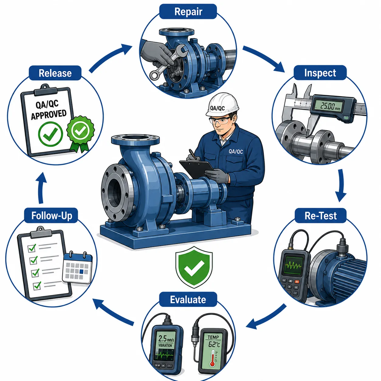
Follow-up inspection provides an additional layer of assurance after the repair has been completed and, where appropriate, after the equipment has operated under controlled conditions. It helps identify defects that may not be visible during static inspection but become apparent during operation. A disciplined verification process therefore follows the principle of “repair, inspect, test, monitor, verify, release.” This approach supports mechanical asset integrity, reliability, production continuity, quality assurance, and evidence-based maintenance decisions.
Understanding Repair Verification
Repair verification is the structured process of collecting objective evidence to demonstrate that corrective maintenance has achieved the required outcome. It connects the original quality deficiency with the final condition of the repaired equipment.
The verification process should answer several fundamental questions:
- Was the original defect corrected?
- Was the repair completed according to the approved method?
- Are the repaired dimensions within specification?
- Are related components still satisfactory?
- Has the repair introduced any new defect?
- Does the assembly function correctly?
- Does the equipment operate within defined limits?
- Has the original failure mechanism been controlled?
- Is additional monitoring required?
- Can the equipment be safely released to production?
Verification should be proportionate to the criticality of the equipment and the potential consequences of failure.
Key Concepts
| Concept | Definition | Practical Application |
|---|---|---|
| Re-Testing | Repeating or selecting tests after repair to confirm corrective effectiveness | Rechecking vibration after shaft alignment |
| Follow-Up Inspection | Inspection conducted after repair or initial operation to confirm continuing condition | Inspecting a repaired gearbox after controlled operation |
| Acceptance Criteria | Defined technical limits used to determine whether the repair is successful | Shaft runout within specified tolerance |
| Functional Test | Test demonstrating that equipment performs its intended function | Running a pump and checking flow and pressure |
| Performance Test | Test comparing operating performance with defined requirements | Checking pump output and efficiency indicators |
| Verification Evidence | Objective information demonstrating conformity | Measurements, test results and inspection records |
| Conditional Release | Controlled return to service subject to defined monitoring or restrictions | Releasing equipment with enhanced vibration monitoring |
| Final Release | Formal authorisation to return equipment to normal production | QA/QC and engineering acceptance after successful testing |
Why Re-Testing Is Essential
Mechanical failures can have multiple contributing factors. A repair may correct one visible problem without eliminating the underlying cause. Re-testing provides evidence that the corrective action has achieved its intended result.
For example, replacing a failed bearing may restore operation temporarily, but if the shaft remains misaligned, the new bearing may fail again. A suitable verification programme would therefore include bearing installation checks, shaft alignment, vibration monitoring, temperature measurement, and controlled operational testing.
Re-testing helps to:
- Confirm repair effectiveness.
- Detect residual defects.
- Identify secondary damage.
- Confirm equipment performance.
- Validate engineering assumptions.
- Demonstrate conformity.
- Reduce premature failure.
- Support safe return to production.
- Provide evidence for quality-record closure.
The most important principle is that testing should be linked directly to the failure mechanism and corrective action.
Developing a Targeted Re-Testing Strategy
Start With the Original Deficiency
The original non-conformance or failure report should be the starting point for verification planning. The QA/QC team should review what failed, why it failed, how it was repaired, and what evidence is necessary to demonstrate successful correction.
For example:
- Shaft runout → dimensional runout measurement
- Bearing failure → clearance, lubrication, temperature and vibration checks
- Gear damage → gear condition and contact verification
- Leakage → pressure and leak testing
- Misalignment → alignment measurement and operational vibration monitoring
- Weld defect → visual and applicable NDT examination
- Excessive corrosion → thickness measurement and condition assessment
This prevents generic testing from replacing technically meaningful verification.
Review the Corrective Action
The corrective action itself determines which tests should be performed.
The review should consider:
- Repair method
- Component criticality
- Material used
- Dimensions changed
- Components replaced
- Welding performed
- Machining performed
- Alignment activities
- Assembly changes
- Operating conditions
- Original failure mechanism
- Potential secondary effects
If the repair changed a component’s geometry, dimensional verification may be essential. If the repair involved welding, additional inspection or NDT may be necessary. If the repair affected a rotating assembly, operational monitoring may be required.
Establishing Acceptance Criteria
Why Acceptance Criteria Matter
A test result has limited meaning unless there is a defined basis for acceptance. “The machine is running normally” is not sufficient for high-quality verification.
Acceptance criteria may come from:
- Approved engineering drawings
- Equipment specifications
- Manufacturer instructions
- Engineering calculations
- Maintenance procedures
- Inspection specifications
- Applicable standards
- Approved repair procedures
- Contract requirements
- Organisational technical requirements
The criteria should be known before testing begins whenever practical.
Examples of Acceptance Criteria
Depending on the equipment, acceptance criteria may address:
- Dimensional tolerance
- Shaft runout
- Bearing clearance
- Alignment
- Pressure
- Temperature
- Vibration
- Leakage
- Speed
- Flow
- Torque
- Gear backlash
- Surface condition
- Functional response
- Protective-device operation
Acceptance criteria should distinguish between normal operating values, warning limits, and unacceptable conditions where appropriate.
Planning the Re-Testing Process
A structured verification plan should identify what will be tested, who will conduct the test, what equipment will be used, what conditions will apply, and how results will be recorded.
Typical Verification Planning Sequence
- Review original defect.
- Review corrective action.
- Identify failure mechanism.
- Identify critical characteristics.
- Select appropriate inspection methods.
- Select appropriate test methods.
- Establish acceptance criteria.
- Confirm calibrated instruments.
- Identify responsible personnel.
- Establish inspection and test points.
- Define controlled operating conditions.
- Conduct initial verification.
- Conduct functional testing.
- Conduct performance checks.
- Review results.
- Conduct follow-up inspection where required.
- Evaluate residual risks.
- Prepare final verification report.
- Obtain release approval.
- Monitor equipment after return to production.
Pre-Test Inspection
Before conducting operational testing, a final static inspection should confirm that the repaired equipment is physically ready for operation.
The pre-test inspection may include:
- Correct component installation
- Fastener security
- Correct torque
- Alignment
- Lubrication
- Sealing
- Guards
- Connections
- Instrumentation
- Identification
- Cleanliness
- Removal of temporary supports
- Removal of tools and foreign objects
- Correct configuration
This inspection reduces the likelihood of damaging the repaired equipment during testing.
Calibration and Test Equipment Control
Reliable verification depends on reliable measuring instruments. An inaccurate instrument can produce a false acceptance or false failure.
QA/QC personnel should verify:
- Calibration status
- Calibration validity
- Instrument identification
- Measurement range
- Resolution
- Suitability for the application
- Environmental limitations
- Correct test method
Examples include:
- Calipers
- Micrometers
- Dial indicators
- Alignment systems
- Pressure gauges
- Temperature instruments
- Vibration analysers
- Torque tools
- Thickness gauges
- Electrical test instruments where relevant
The measurement system should be appropriate to the tolerance or performance parameter being evaluated.
Dimensional Re-Testing
Mechanical Dimensions
Dimensional verification is particularly important where machining, grinding, resurfacing, component replacement, or adjustment has been performed.
Measurements may include:
- Diameter
- Length
- Thickness
- Bore
- Clearance
- Runout
- Flatness
- Concentricity
- Parallelism
- Perpendicularity
- Surface condition
The results should be compared with approved requirements.
Example: Shaft Repair
If a shaft was repaired because of excessive runout, final verification should not simply confirm the shaft’s diameter. The shaft should also be checked for:
- Runout
- Straightness
- Journal condition
- Bearing fit
- Surface condition
- Relevant geometric relationships
This demonstrates why targeted testing should reflect the actual failure mechanism.
Alignment Verification
Alignment should be verified after corrective work involving rotating assemblies.
Applications include:
- Pumps
- Compressors
- Gearboxes
- Motors
- Turbines
- Fans
- Coupled shafts
- Drive systems
The verification should confirm that the final alignment satisfies the applicable requirements under the relevant equipment conditions.
Poor alignment can produce:
- Excessive vibration
- Bearing damage
- Seal failure
- Coupling wear
- Shaft fatigue
- Increased energy consumption
- Premature component failure
Functional Testing
Purpose of Functional Testing
Functional testing demonstrates whether the repaired system performs its intended basic function.
For a pump, this might involve:
- Rotation
- Flow
- Pressure
- Vibration
- Temperature
- Leakage
For a compressor, it may include:
- Start-up
- Pressure response
- Temperature
- Vibration
- Lubrication
- Flow or output
For a gearbox, it may include:
- Rotation
- Noise
- Temperature
- Vibration
- Speed
- Load response
Functional testing should be conducted in a controlled manner.
Controlled Start-Up
A repaired mechanical system should often be introduced back into service progressively rather than immediately operating at maximum conditions.
A controlled start-up can involve:
Stage 1: Initial Rotation
Check for:
- Abnormal noise
- Unexpected movement
- Leakage
- Incorrect rotation
- Immediate vibration
Stage 2: Low Operating Condition
Monitor:
- Temperature
- Vibration
- Pressure
- Flow
- Lubrication
- Noise
Stage 3: Progressive Increase
Where appropriate, gradually increase operating conditions while continuing to monitor critical parameters.
Stage 4: Normal Operating Condition
Compare operating performance with established requirements.
Stage 5: Stabilisation
Continue monitoring until the equipment demonstrates stable performance.
This approach reduces the risk of allowing a hidden defect to develop into a major failure.
Vibration Re-Testing
Vibration is an important indicator for rotating machinery. It can provide evidence of:
- Misalignment
- Imbalance
- Bearing problems
- Looseness
- Gear defects
- Structural problems
- Resonance
- Installation problems
When vibration was part of the original failure, post-repair vibration testing should be a key verification activity.
Testing should consider:
- Measurement location
- Operating speed
- Load condition
- Measurement direction
- Baseline condition
- Previous readings
- Acceptance limits
- Trend information
A single reading may be useful, but trend comparison can provide stronger evidence of long-term improvement.
Temperature Monitoring
Temperature monitoring is useful for bearings, gearboxes, motors, compressors, pumps, and other mechanical systems.
An abnormal increase may indicate:
- Excessive friction
- Poor lubrication
- Misalignment
- Overloading
- Incorrect clearance
- Bearing problems
- Seal problems
After repair, temperature should be monitored during controlled operation and compared with appropriate limits or baseline values.
Pressure and Leak Testing
Where corrective maintenance affects pressure-containing equipment or sealed systems, pressure and leakage verification may be essential.
Testing should confirm:
- Correct test pressure
- Correct test duration
- Suitable test equipment
- Safe test conditions
- No unacceptable leakage
- No deformation
- Stable pressure where required
- Correct documentation
Pressure testing should be performed under an approved procedure appropriate to the equipment and service.
Follow-Up Inspections
Why Follow-Up Inspection Is Different
Final inspection immediately after repair provides evidence of the initial condition. Follow-up inspection provides evidence that the repair remains effective after the equipment has experienced operation.
This is particularly valuable for repairs involving:
- Rotating equipment
- Structural components
- Weld repairs
- Temporary repairs
- Reworked surfaces
- Critical bearings
- Pressure-containing components
- Repeated failure mechanisms
Follow-up inspection can be scheduled after a defined period of operation or after a specific number of operating cycles.
Follow-Up Activities
Possible activities include:
- Visual inspection
- Vibration review
- Temperature monitoring
- Leakage inspection
- Dimensional checks
- Lubrication inspection
- Fastener verification
- NDT where appropriate
- Performance comparison
- Maintenance record review
Case Study: Verification of a Repaired Centrifugal Pump
Background
A centrifugal pump was removed from service after excessive vibration and elevated bearing temperature were detected. Inspection identified bearing deterioration and shaft misalignment.
The corrective action included:
- Bearing replacement
- Shaft inspection
- Alignment correction
- Lubrication
- Coupling inspection
Verification Plan
Before release, the QA/QC team establishes a targeted verification programme.
The plan includes:
- Visual inspection.
- Bearing installation verification.
- Shaft alignment measurement.
- Coupling inspection.
- Lubrication verification.
- Manual rotation.
- Controlled start-up.
- Vibration measurement.
- Bearing temperature monitoring.
- Leakage inspection.
- Flow and pressure confirmation.
- Post-operation inspection.
Test Results
During initial operation, vibration remains within the specified acceptance range and bearing temperature stabilises at an acceptable level. Flow and pressure also meet the required operating condition.
After several hours of controlled operation, a follow-up inspection confirms that there is no abnormal leakage, overheating, or unusual vibration trend.
The QA/QC team reviews the results and confirms that the original deficiency has been addressed.
Case Study Outcome
The pump is released back into production with a documented verification record. Because the original failure involved vibration and bearing condition, enhanced monitoring is scheduled during the early period following reinstatement.
This demonstrates an important principle: verification does not necessarily end when the first functional test is passed. The level of follow-up should reflect equipment criticality and failure risk.
Practical Example: Repaired Gearbox
A gearbox has experienced abnormal noise caused by damaged gear teeth and incorrect bearing clearance.
The repair includes replacement of the damaged gear and bearing adjustment.
Targeted Verification
The verification programme includes:
- Gear visual inspection
- Gear tooth condition
- Bearing clearance
- Shaft rotation
- Lubrication
- Housing closure
- Alignment
- No-load testing
- Temperature monitoring
- Vibration monitoring
- Noise assessment
- Controlled load testing
Follow-Up
After initial operation, the gearbox is inspected again for:
- Abnormal temperature
- Oil leakage
- Metal particles
- Vibration changes
- Unusual noise
- Gear contact condition
The results are compared with the baseline established after repair.
Handling Failed Verification Results
Not every repaired system will pass verification on the first attempt. A failed test should be treated as engineering evidence rather than simply repeated until a favourable result appears.
When verification fails:
- Stop the release process.
- Record the failed result.
- Identify the affected parameter.
- Compare the result with the acceptance criterion.
- Investigate possible causes.
- Determine whether the original repair was effective.
- Inspect related components.
- Review test equipment.
- Confirm measurement validity.
- Conduct additional engineering assessment.
- Develop further corrective action.
- Repeat testing after the new intervention.
For example, if vibration remains excessive after alignment, the investigation should consider imbalance, bearing condition, foundation movement, coupling condition, resonance, or other contributing factors.
Distinguishing Test Failure from Measurement Error
A failed test result does not always mean that the equipment itself has failed. The measurement system must also be considered.
Possible causes include:
- Incorrect instrument
- Calibration issue
- Incorrect measurement location
- Incorrect test condition
- Operator error
- Data recording error
- Environmental interference
- Incorrect acceptance criterion
The QA/QC process should therefore confirm the validity of the test before concluding that the repaired equipment is defective.
Release Decision-Making
Conditions for Release
A repaired system should only return to normal production when sufficient evidence demonstrates that the defined requirements have been met.
Release considerations may include:
- Corrective work completed
- Final inspection completed
- Critical dimensions verified
- Assembly verified
- Functional test passed
- Performance requirements satisfied
- Safety controls restored
- Documentation complete
- Outstanding NCRs addressed
- Engineering approval obtained where required
- QA/QC acceptance completed
Conditional Release
In some circumstances, a controlled conditional release may be appropriate where residual risk is understood, authorised, and subject to additional monitoring. Such decisions should be formally controlled.
Conditions might include:
- Restricted operating load
- Increased inspection frequency
- Additional vibration monitoring
- Shortened maintenance interval
- Temporary engineering controls
- Defined review date
Conditional release should not become a substitute for completing necessary corrective work.
Documentation of Verification
Verification Records
A complete verification package may contain:
- Original defect report
- Corrective action report
- Repair procedure
- Inspection records
- Dimensional measurements
- Material records
- Calibration information
- NDT results
- Alignment records
- Functional test results
- Performance test results
- Photographs
- Follow-up inspection results
- Final acceptance
- Release authorisation
These records provide evidence that the repair was not only completed but also independently verified against defined requirements.
Traceability
Traceability allows future engineering teams to determine:
- What failed?
- What was repaired?
- Which components were replaced?
- What tests were performed?
- What were the results?
- Who verified the work?
- When was the equipment released?
- Was additional monitoring required?
This information can become extremely valuable during future maintenance planning and failure investigations.
Trend Monitoring After Repair
Why Trends Matter
A repaired system may initially perform satisfactorily but gradually deteriorate. Trend monitoring can identify early changes before they develop into another major failure.
Useful parameters include:
- Vibration
- Temperature
- Pressure
- Flow
- Lubricant condition
- Leakage
- Noise
- Power consumption
- Operating speed
Trend information can demonstrate whether the corrective action has produced stable improvement.
Baseline Data
A post-repair baseline should be established where appropriate. This baseline provides a reference point for future inspections.
For example:
Before repair: excessive vibration
After repair: vibration reduced to acceptable level
Follow-up: vibration remains stable
This sequence provides stronger evidence of corrective effectiveness than a single final measurement.
Key Benefits of Targeted Re-Testing and Follow-Up Inspection
Improved Safety
Testing reduces the likelihood of releasing equipment with hidden defects that could create hazardous conditions.
Improved Reliability
Verification demonstrates whether the repair has restored dependable operation.
Reduced Repeat Failures
Targeted testing can reveal whether the original failure mechanism has actually been controlled.
Reduced Production Risk
Controlled release reduces the possibility of unexpected equipment failure after returning to production.
Better Quality Assurance
Documented verification provides objective evidence of conformity.
Improved Maintenance Planning
Post-repair performance data can be used to determine future inspection frequency and maintenance requirements.
Stronger Asset Integrity
Follow-up inspection helps ensure that repairs continue to support the intended mechanical integrity of the equipment.
Better Engineering Decisions
Reliable test results support evidence-based decisions about repair effectiveness, replacement, monitoring, and future maintenance.
Common Verification Mistakes to Avoid
Several weaknesses can reduce the effectiveness of post-repair verification.
Releasing Equipment Immediately After Repair
Physical completion does not demonstrate operational compliance.
Using Generic Tests
Testing should be directly related to the original defect and corrective action.
Ignoring Acceptance Criteria
Results cannot be objectively assessed without defined requirements.
Using Uncalibrated Equipment
Poor measurement control can invalidate verification results.
Testing Only at No Load
Some mechanical defects become apparent only under realistic operating conditions.
Ignoring Follow-Up Monitoring
A repair may pass initial testing but deteriorate after returning to service.
Repeating a Failed Test Without Investigation
Repeated testing without understanding the failure can conceal the actual problem.
Poor Documentation
Incomplete verification records weaken traceability and future decision-making.
Recommended Verification Workflow
A practical verification workflow can be structured as follows:
Stage 1: Review
- Review the original deficiency.
- Review corrective action.
- Identify critical failure mechanisms.
- Determine verification requirements.
Stage 2: Prepare
- Establish acceptance criteria.
- Prepare test equipment.
- Verify calibration.
- Confirm safety controls.
- Brief personnel.
Stage 3: Inspect
- Conduct final visual inspection.
- Verify dimensions.
- Confirm assembly.
- Check alignment.
- Confirm lubrication.
Stage 4: Test
- Conduct functional testing.
- Start equipment under controlled conditions.
- Monitor critical parameters.
- Compare results with acceptance criteria.
Stage 5: Evaluate
- Review test results.
- Confirm conformity.
- Investigate anomalies.
- Determine whether additional testing is required.
Stage 6: Follow Up
- Monitor equipment after operation.
- Conduct scheduled inspection.
- Compare results with baseline.
- Review trends.
Stage 7: Release
- Complete documentation.
- Confirm all requirements are satisfied.
- Obtain required approvals.
- Return equipment to production.
Stage 8: Learn
- Record lessons learned.
- Update maintenance information.
- Review recurring failure patterns.
- Improve future inspection and maintenance strategies.
Integrating Verification with Continual Improvement
Repair verification should not be considered an isolated final step. The information generated during testing can improve future maintenance and QA/QC activities.
For example, if a repaired pump shows stable vibration levels after repair, the results can establish a new baseline. If vibration begins increasing again several months later, the trend can trigger earlier investigation.
Similarly, if multiple gearboxes experience similar bearing failures, the organisation can review:
- Bearing selection
- Installation procedures
- Lubrication practices
- Alignment controls
- Operating loads
- Inspection frequency
- Maintenance competence
This transforms corrective maintenance data into organisational knowledge.
Professional Decision-Making Before Production Release
The final release decision should be based on evidence rather than production pressure. QA/QC personnel should be prepared to delay release when the available evidence does not demonstrate conformity.
Before release, the responsible team should be able to demonstrate that:
- The original defect has been addressed.
- The corrective action was completed correctly.
- Critical dimensions meet requirements.
- Related components are satisfactory.
- Functional tests are acceptable.
- Performance is within defined limits.
- Safety controls are restored.
- Required records are complete.
- Any residual risk is understood and authorised.
- Follow-up monitoring is established where required.
This approach protects both the equipment and the organisation from premature return to service.
Case Study: Failed Post-Repair Verification
Scenario
A compressor undergoes corrective maintenance after excessive vibration is detected. The coupling is realigned and a bearing is replaced. Initial testing shows a reduction in vibration, but the level remains above the specified acceptance criterion.
Initial Response
The equipment is not released to normal production. Instead, the QA/QC team reviews:
- Alignment measurements
- Bearing installation
- Coupling condition
- Shaft condition
- Foundation condition
- Vibration measurement method
- Operating speed
- Test instrument calibration
Further inspection identifies an imbalance in the rotating assembly.
Additional Corrective Action
The imbalance is corrected, and the compressor undergoes another controlled test. Vibration is then measured again and falls within the required range.
A follow-up inspection is scheduled after an initial operating period.
The case demonstrates that verification is not merely a formality. It provides a technical decision point. The initial repair reduced the symptom but did not completely restore compliance. Targeted re-testing identified the remaining deficiency before the compressor was returned to normal production.
Conclusion
Targeted re-testing and follow-up inspection are essential for demonstrating that completed mechanical repairs have genuinely restored equipment to a safe, reliable, and operationally compliant condition. Effective verification begins with the original defect and corrective action, allowing QA/QC professionals to select tests that directly address the failure mechanism and the risks associated with the repair. Dimensional checks, alignment verification, functional testing, vibration monitoring, temperature measurement, pressure or leak testing, and controlled start-up activities can provide objective evidence that the repaired assembly satisfies its defined requirements.
The verification process should continue beyond the initial repair where equipment criticality or failure risk justifies follow-up monitoring. By establishing post-repair baselines, reviewing operating trends, documenting results, investigating failed tests, and controlling the final release decision, organisations can reduce repeat failures and protect production reliability. The fundamental principle is that a repaired system should not return to normal production simply because maintenance work has been completed; it should be released only when inspection, testing, engineering evidence, QA/QC verification, and appropriate follow-up demonstrate that the system is fit for its intended service.