
Lesson 1: Perform comprehensive inspections of mechanical systems, machinery, and components.
Comprehensive mechanical inspections are essential for verifying the condition, quality, functionality, and integrity of machinery, equipment, assemblies, and individual mechanical components throughout their operational lifecycle. Effective inspection practices help identify visible defects, dimensional deviations, material deterioration, abnormal wear, corrosion, leakage, misalignment, vibration-related issues, assembly deficiencies, and other conditions that may affect mechanical performance or reliability. This lesson explores systematic mechanical inspection methods that support quality assurance, quality control, asset integrity, preventive maintenance, and safe engineering operations across manufacturing facilities, workshops, construction projects, industrial plants, and mechanical installation environments.
The inspection process requires more than simply observing equipment for visible damage. A professional mechanical inspection involves reviewing relevant technical information, establishing inspection requirements, selecting suitable inspection methods, examining components against defined criteria, recording objective findings, and determining whether equipment remains suitable for its intended function. Inspection activities may involve visual examination, dimensional checks, alignment verification, condition assessment, component inspection, documentation review, and the identification of potential deterioration mechanisms. Accurate inspection records and traceable evidence are particularly important because they provide a reliable basis for maintenance planning, corrective action, non-conformance management, and engineering decision-making.
A structured approach to mechanical system inspection can improve equipment reliability, reduce unexpected failures, minimise rework, and support long-term operational performance. By understanding how to inspect mechanical systems systematically, engineering personnel can distinguish acceptable conditions from defects requiring further investigation or corrective action. The lesson therefore connects inspection techniques with practical QA/QC objectives, mechanical integrity, reliability improvement, workplace risk management, and continual improvement, helping establish consistent inspection practices that support safe, efficient, and dependable mechanical engineering operations.
1: Critically Evaluate the Structural Design and Operational Limits of Complex Mechanical Machinery Before Starting Physical Inspection Procedures
Before any physical inspection of complex mechanical machinery begins, the inspection team must establish a clear understanding of how the equipment is designed, how it is intended to operate, and which operating conditions define its safe and acceptable performance. Mechanical inspection is not simply a visual activity; it is an engineering evaluation that must be informed by design information, equipment functions, operating parameters, loading conditions, materials, construction details, known failure mechanisms, and defined acceptance criteria. A critical review before inspection allows the inspection team to identify vulnerable components, understand where deterioration is most likely to occur, determine appropriate inspection methods, and avoid exposing personnel or equipment to unnecessary risk.
Complex machinery can contain interacting mechanical systems such as shafts, bearings, gears, couplings, seals, pressure-containing components, rotating assemblies, structural frames, lubrication systems, cooling arrangements, drive systems, valves, actuators, and protective devices. Each component operates within specific limits relating to load, speed, temperature, pressure, vibration, alignment, lubrication, material strength, and duty cycle. Exceeding these limits may accelerate deterioration or create conditions that compromise mechanical integrity. Therefore, a professional inspection strategy begins by interpreting available engineering information and establishing the relationship between design intent, actual operating conditions, potential deterioration, and inspection requirements.

Understanding Structural Design Before Inspection
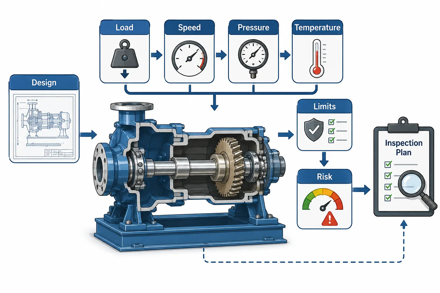
Structural design refers to the configuration, geometry, materials, connections, supporting arrangements, and load-bearing characteristics that enable machinery to perform its intended function. Understanding the structural design allows an inspector to identify which components carry mechanical loads, which parts transmit power, which areas are exposed to stress concentration, and which interfaces are particularly susceptible to deterioration.
Before physical inspection, relevant design information should be reviewed to understand:
- Equipment configuration.
- Main load-bearing components.
- Rotating components.
- Fixed structural components.
- Pressure-containing sections.
- Welded connections.
- Bolted connections.
- Bearings and supports.
- Shafts and couplings.
- Gear arrangements.
- Seals and containment systems.
- Lubrication arrangements.
- Cooling systems.
- Guarding and protective arrangements.
The inspection should then be structured around the actual design and function of the equipment rather than relying on a generic checklist.
Why Pre-Inspection Engineering Evaluation Matters
A pre-inspection evaluation provides an opportunity to identify important technical issues before personnel interact physically with the machinery.
It helps inspectors determine:
- What components require priority inspection.
- Which components are safety-critical.
- Where deterioration is most likely.
- Which operating conditions could influence inspection findings.
- Which areas require specialist inspection techniques.
- What access arrangements are necessary.
- Whether equipment must be isolated or stopped.
- Which inspection criteria should be applied.
- What historical problems require particular attention.
This makes the inspection more systematic and evidence-based.
Key Definitions and Concepts
| Term | Definition | Mechanical Inspection Application |
|---|---|---|
| Structural Design | Arrangement and configuration that enables equipment to withstand intended loads | Reviewing frames, shafts and load-bearing assemblies |
| Operational Limit | Defined boundary within which machinery is intended to operate | Maximum speed, temperature, pressure or load |
| Design Load | Load considered during equipment design | Reviewing shaft or structural loading |
| Operating Load | Actual load experienced during operation | Comparing real conditions with design assumptions |
| Mechanical Integrity | Ability of equipment to remain structurally sound and functional | Assessing machinery condition |
| Design Pressure | Pressure for which pressure-containing equipment is designed | Reviewing pressure-vessel limitations |
| Design Temperature | Temperature considered in equipment design | Evaluating thermal operating limits |
| Rated Speed | Speed specified for intended equipment operation | Assessing rotating machinery |
| Allowable Stress | Permitted stress level for a component or material | Evaluating structural adequacy |
| Fatigue | Progressive damage caused by repeated cyclic loading | Inspecting shafts, welds and structural areas |
| Stress Concentration | Localised area where stress becomes higher than surrounding material | Reviewing keyways, welds and sharp transitions |
| Deterioration Mechanism | Process through which equipment condition declines | Corrosion, wear, fatigue or erosion |
| Acceptance Criteria | Defined requirements used to determine conformity | Assessing inspection findings |
| Design Intent | Functional and structural purpose established during design | Comparing actual performance with intended operation |
| Mechanical Failure Mode | Specific manner in which equipment can fail | Bearing seizure, shaft fracture or leakage |
Reviewing Design Documentation
A professional pre-inspection review should begin with available technical documentation.
Depending on the equipment, this may include:
- General arrangement drawings.
- Assembly drawings.
- Mechanical drawings.
- Equipment datasheets.
- Manufacturer documentation.
- Design calculations.
- Material specifications.
- Welding documentation.
- Operating manuals.
- Maintenance manuals.
- Inspection history.
- Previous repair records.
- Modification records.
- Performance data.
- Calibration records.
- Test certificates.
The objective is not to collect documents for administrative purposes but to establish an engineering understanding of the equipment.
Understanding Equipment Function
The inspector should understand what the machinery is designed to accomplish.
For example, a pump may be designed to:
- Transfer a specified fluid.
- Operate at a defined flow range.
- Maintain a specified pressure differential.
- Operate within a particular temperature range.
- Run at a defined rotational speed.
A compressor may have:
- Defined pressure ratios.
- Maximum discharge pressure.
- Temperature limitations.
- Rated rotational speed.
- Specific lubrication requirements.
Understanding these functions provides context for inspection.
Design Parameters
Important design parameters can include:
- Pressure.
- Temperature.
- Speed.
- Torque.
- Load.
- Flow.
- Power.
- Material strength.
- Shaft diameter.
- Wall thickness.
- Bearing capacity.
- Vibration limits.
- Alignment tolerances.
These parameters establish the expected operating envelope.
Operational Limits
Operational limits are boundaries within which machinery is intended to function safely and reliably.
Typical limits include:
Maximum Pressure
Excessive pressure can cause structural or containment failure.
Maximum Temperature
High temperature can affect materials, lubrication, seals and dimensional stability.
Maximum Speed
Excessive rotational speed can increase centrifugal forces, vibration and bearing loads.
Maximum Load
Overloading can increase stresses and accelerate fatigue or wear.
Permitted Vibration
Excessive vibration may indicate imbalance, misalignment, looseness or component deterioration.
Lubrication Limits
Incorrect lubricant quantity or condition can cause accelerated component deterioration.
Comparing Design and Actual Operating Conditions
One of the most important pre-inspection activities is comparing intended operating conditions with actual conditions.
For example:
| Parameter | Design Requirement | Actual Condition | Inspection Significance |
|---|---|---|---|
| Speed | 3,000 rpm | 3,150 rpm | Potential overload concern |
| Temperature | 80°C | 92°C | Increased deterioration risk |
| Pressure | 12 bar | 11.5 bar | Within stated limit |
| Vibration | Defined limit | Increasing trend | Further investigation |
| Load | Rated capacity | Near maximum | Increased fatigue consideration |
The purpose is to identify areas where operating conditions may have contributed to deterioration.
Reviewing Mechanical Loads
Mechanical machinery can experience different forms of loading.
These include:
- Tensile loading.
- Compression.
- Bending.
- Torsion.
- Shear.
- Cyclic loading.
- Impact loading.
- Combined loading.
The inspector should understand which components are exposed to which loading conditions.
Rotating Equipment Assessment
Rotating machinery requires particular attention because rotational forces can significantly influence mechanical integrity.
Important considerations include:
- Shaft condition.
- Bearing condition.
- Coupling condition.
- Rotor balance.
- Alignment.
- Lubrication.
- Vibration.
- Rotational speed.
- Operating temperature.
Potential deterioration may occur when operating conditions exceed intended limits.
Shaft Design and Inspection Considerations
Shafts transmit torque and may experience bending and cyclic loading.
Pre-inspection evaluation should consider:
- Shaft diameter.
- Material.
- Keyways.
- Coupling locations.
- Bearing positions.
- Stress concentrations.
- Operating speed.
- Historical failures.
Areas containing changes in geometry may require increased inspection attention.
Bearing Systems
Bearings support rotating components and control movement.
Important design and operating factors include:
- Load capacity.
- Rotational speed.
- Lubrication.
- Temperature.
- Alignment.
- Installation condition.
Potential inspection concerns include:
- Wear.
- Overheating.
- Lubrication deterioration.
- Surface damage.
- Excessive clearance.
- Abnormal vibration.
Gear Systems
Gears transmit power and torque.
Pre-inspection evaluation should consider:
- Gear ratio.
- Operating speed.
- Load.
- Lubrication.
- Tooth geometry.
- Alignment.
- Contact patterns.
Potential deterioration includes:
- Tooth wear.
- Pitting.
- Scuffing.
- Cracking.
- Surface damage.
Welded Structures
Welded mechanical structures can contain areas of stress concentration and may be vulnerable to fatigue or fabrication-related defects.
Pre-inspection review should consider:
- Weld locations.
- Joint configuration.
- Material.
- Loading conditions.
- Previous repairs.
- Known defect history.
Inspection requirements should reflect the significance of the weld to structural integrity.
Bolted Connections
Bolted connections may be affected by:
- Incorrect tightening.
- Loosening.
- Cyclic loading.
- Corrosion.
- Misalignment.
- Joint movement.
The inspector should understand the function of each connection before deciding how it should be examined.
Pressure-Containing Equipment
Pressure-containing components require careful evaluation because failure may have significant consequences.
Important parameters include:
- Design pressure.
- Operating pressure.
- Design temperature.
- Operating temperature.
- Material.
- Wall thickness.
- Corrosion allowance.
- Weld configuration.
- Previous inspection results.
Physical inspection should be planned around known deterioration mechanisms.
Materials and Mechanical Integrity
Material properties influence how machinery behaves under operating conditions.
Pre-inspection review should consider:
- Material grade.
- Strength.
- Hardness.
- Corrosion resistance.
- Temperature capability.
- Wear resistance.
- Compatibility with operating conditions.
Material-related information can help explain observed deterioration.
Understanding Stress Concentration
Stress concentration occurs when a local geometry causes stresses to become higher than those in surrounding material.
Examples include:
- Sharp corners.
- Keyways.
- Holes.
- Threads.
- Weld toes.
- Abrupt section changes.
These locations may require particular inspection attention where cyclic loading is present.
Fatigue Considerations
Fatigue is especially important where equipment experiences repeated loading.
Potential fatigue-sensitive areas include:
- Shafts.
- Welded joints.
- Structural frames.
- Couplings.
- Pressure equipment.
- Rotating components.
Before inspection, the inspector should determine whether equipment has experienced:
- High cycle frequency.
- Load variation.
- Vibration.
- Start-stop operation.
- Thermal cycling.
Corrosion Considerations
Corrosion can reduce material thickness and compromise structural integrity.
The pre-inspection review should consider:
- Operating environment.
- Fluid characteristics.
- Material selection.
- Temperature.
- Previous corrosion rates.
- Protective systems.
This helps determine where inspection should focus.
Wear Mechanisms
Wear can occur where surfaces interact mechanically.
Potential causes include:
- Friction.
- Abrasion.
- Contamination.
- Poor lubrication.
- Misalignment.
- Excessive loading.
The inspector should identify components where wear is functionally significant.
Thermal Effects
Temperature changes can influence mechanical equipment through:
- Thermal expansion.
- Thermal contraction.
- Material property changes.
- Lubricant degradation.
- Seal deterioration.
- Thermal stress.
Inspection planning should therefore consider operating temperature and temperature cycling.
Vibration as a Pre-Inspection Indicator
Vibration data can provide valuable information before physical inspection.
An increasing vibration trend may indicate:
- Imbalance.
- Misalignment.
- Bearing deterioration.
- Mechanical looseness.
- Foundation problems.
- Resonance.
Historical vibration data can help inspectors determine which components require closer attention.
Reviewing Operating History
Operating history can reveal patterns that are not visible during a single inspection.
Important historical information includes:
- Previous failures.
- Emergency shutdowns.
- Repairs.
- Overloads.
- Abnormal operating conditions.
- Maintenance frequency.
- Repeated NCRs.
- Previous inspection findings.
This evidence should influence inspection planning.
Reviewing Maintenance History
Maintenance records can reveal:
- Repeated component replacement.
- Recurring defects.
- Poor repair outcomes.
- Changes in maintenance frequency.
- Unresolved deterioration.
Repeated repairs may indicate that the underlying failure mechanism has not been adequately addressed.
Reviewing Previous Inspection Reports
Previous inspection findings provide a baseline for evaluating deterioration.
The inspector should compare:
- Previous measurements.
- Current expected condition.
- Defect progression.
- Repair history.
- Remaining integrity concerns.
Trend analysis is often more useful than reviewing a single inspection result.
Evaluating Modifications
Machinery may have been modified after its original installation.
Examples include:
- Component replacement.
- Structural reinforcement.
- New piping.
- Drive changes.
- Control modifications.
- Material substitution.
Modifications can change loads or operating behaviour and should therefore be considered before inspection.
Management of Change
Where equipment has been modified, the inspection team should establish:
- What changed.
- Why it changed.
- Who approved it.
- What technical basis supported it.
- Whether operating limits changed.
- Whether inspection requirements changed.
This helps prevent inspections from being based on obsolete design assumptions.
Pre-Inspection Risk Assessment
A risk assessment should identify hazards associated with the inspection activity.
Consider:
- Stored energy.
- Rotating components.
- Pressure.
- Temperature.
- Hazardous fluids.
- Access limitations.
- Heavy components.
- Electrical interfaces.
- Confined spaces.
- Work at height.
The inspection plan should incorporate appropriate controls.
Establishing Inspection Boundaries
Before inspection begins, define:
- Equipment to be inspected.
- Components included.
- Components excluded.
- Operating state.
- Inspection location.
- Inspection depth.
- Acceptance criteria.
Clear boundaries prevent gaps and duplication.
Selecting Inspection Methods
Inspection methods should be matched to the component and suspected deterioration.
Possible methods include:
- Visual examination.
- Dimensional inspection.
- Measurement.
- Alignment verification.
- Surface examination.
- Non-destructive testing.
- Thickness measurement.
- Functional testing.
Method selection should be technically justified.
Acceptance Criteria
Inspection findings should be assessed against defined criteria.
Acceptance criteria may consider:
- Dimensions.
- Tolerances.
- Defect size.
- Surface condition.
- Alignment.
- Wear limits.
- Leakage.
- Vibration.
- Functional performance.
An inspector should not rely solely on personal judgement where objective criteria are available.
Practical Example: Centrifugal Pump
Before inspecting a centrifugal pump, the engineer reviews:
- Rated speed.
- Design flow.
- Pressure.
- Bearing arrangement.
- Shaft configuration.
- Seal arrangement.
- Historical vibration.
- Previous bearing failures.
Historical records show increasing vibration over six months.
The inspection therefore gives additional attention to:
- Bearings.
- Shaft condition.
- Coupling alignment.
- Foundation.
- Lubrication.
- Rotor condition.
This demonstrates how pre-inspection analysis improves inspection effectiveness.
Practical Example: Industrial Compressor
A compressor operates at elevated temperature and pressure.
Before inspection, the engineering team reviews:
- Design pressure.
- Operating pressure.
- Temperature.
- Rated speed.
- Lubrication system.
- Seal configuration.
- Previous failures.
Historical data indicate increasing discharge temperature.
The inspection strategy therefore focuses on:
- Cooling arrangements.
- Lubrication.
- Seals.
- Bearings.
- Operating condition.
Practical Example: Gearbox
A gearbox has experienced repeated gear-tooth damage.
Pre-inspection analysis identifies:
- High operating loads.
- Variable operating cycles.
- Lubrication history.
- Alignment information.
- Previous repair records.
The inspection focuses on:
- Gear teeth.
- Bearing condition.
- Lubricant condition.
- Shaft alignment.
- Housing condition.
Practical Example: Pressure Vessel
A pressure vessel has been operating for several years.
The inspector reviews:
- Design pressure.
- Operating pressure.
- Material.
- Previous thickness readings.
- Corrosion history.
- Weld locations.
If historical measurements indicate increasing wall-thickness loss, inspection attention can be prioritised around susceptible areas.
Practical Example: Mechanical Structural Frame
A structural frame supporting heavy machinery experiences increasing vibration.
The pre-inspection review considers:
- Equipment loads.
- Structural arrangement.
- Anchor points.
- Welds.
- Bolted connections.
- Historical vibration.
The physical inspection can then concentrate on load-transfer areas and potential fatigue-sensitive locations.
Process for Evaluating Design and Operational Limits
Step 1: Identify the Equipment
Confirm equipment type, identification and intended function.
Step 2: Review Design Information
Examine relevant drawings, datasheets and specifications.
Step 3: Establish Operating Parameters
Identify pressure, temperature, speed, load and other relevant conditions.
Step 4: Compare Actual and Design Conditions
Determine whether the machinery operates within intended boundaries.
Step 5: Identify Critical Components
Determine which components have the greatest influence on integrity.
Step 6: Identify Deterioration Mechanisms
Consider corrosion, fatigue, wear, vibration and other mechanisms.
Step 7: Review Historical Evidence
Examine inspection, maintenance and failure records.
Step 8: Assess Inspection Risks
Determine hazards associated with physical inspection.
Step 9: Select Inspection Methods
Choose methods appropriate to the equipment and deterioration mechanism.
Step 10: Establish Acceptance Criteria
Define how findings will be evaluated.
Step 11: Develop the Inspection Plan
Set inspection scope, sequence and responsibilities.
Step 12: Begin Physical Inspection
Proceed only after appropriate technical and safety preparation.
Benefits of Pre-Inspection Design Evaluation
Improved Inspection Quality
Inspectors understand where defects are most likely to occur.
Better Risk Control
Potential hazards and energy sources are identified before inspection.
More Effective Resource Use
Inspection effort can be focused on critical areas.
Better Defect Detection
Knowledge of failure mechanisms supports appropriate inspection methods.
Improved Reliability
Early identification of deterioration supports proactive intervention.
Stronger QA/QC
Inspection findings can be assessed against defined technical criteria.
Better Maintenance Planning
Inspection evidence can support future maintenance decisions.
Improved Asset Integrity
The relationship between design, operation and deterioration becomes clearer.
Common Pre-Inspection Errors
Organisations should avoid:
- Starting physical inspection without reviewing equipment information.
- Ignoring operational limits.
- Relying entirely on visual inspection.
- Using generic inspection checklists without equipment-specific analysis.
- Ignoring historical failures.
- Failing to consider modifications.
- Using incorrect acceptance criteria.
- Ignoring deterioration mechanisms.
- Failing to assess stored energy.
- Treating all machinery components as equally important.
Professional Inspection Decision-Making
A competent inspector should ask:
- What is this component designed to do?
- What loads does it experience?
- What operating conditions does it encounter?
- What are its defined limits?
- What are its likely failure modes?
- What deterioration has occurred previously?
- Which areas are most critical?
- Which inspection method can identify the suspected defect?
- What criteria determine acceptance?
- What hazards must be controlled before inspection?
These questions establish a structured engineering approach.
Integration with QA/QC
Pre-inspection design evaluation should connect with the wider QA/QC system.
Relevant QA/QC information includes:
- Material certificates.
- Manufacturing records.
- Welding documentation.
- Inspection reports.
- Test results.
- NCRs.
- Repair records.
- Calibration records.
- Equipment history.
This creates traceability between original quality and current condition.
Integration with Maintenance
Inspection planning should also connect with maintenance information.
Maintenance records can indicate:
- Recurring failures.
- Frequently replaced components.
- Repeated repairs.
- Lubrication problems.
- Alignment issues.
- Overheating.
- Abnormal vibration.
Combining inspection and maintenance information improves engineering judgement.
Case Study: Pre-Inspection Evaluation of a Critical Pump
Background
A manufacturing plant operates a high-capacity centrifugal pump that is essential to production. The pump has operated continuously for several years and has recently demonstrated increasing vibration and occasional seal leakage.
Initial Review
Before physical inspection, the engineering team reviews:
- Manufacturer documentation.
- Pump datasheet.
- Rated speed.
- Operating pressure.
- Flow conditions.
- Bearing arrangement.
- Seal configuration.
- Maintenance history.
- Previous inspection reports.
Historical Findings
The records indicate:
- Increasing vibration.
- Two previous bearing replacements.
- One seal replacement.
- Several alignment adjustments.
These findings suggest that the problem may involve more than normal component wear.
Design Evaluation
The engineering team reviews:
- Shaft configuration.
- Coupling arrangement.
- Bearing locations.
- Foundation.
- Operating speed.
- Load conditions.
Potential areas of concern include:
- Misalignment.
- Bearing deterioration.
- Shaft condition.
- Foundation movement.
- Coupling condition.
Operational Limit Review
The team compares actual conditions with design requirements.
The pump is operating close to its rated capacity and has experienced periods of elevated temperature.
This information increases the priority of the inspection.
Inspection Strategy
The team establishes a focused inspection covering:
- Visual condition.
- Coupling alignment.
- Bearing condition.
- Shaft condition.
- Seal arrangement.
- Foundation condition.
- Lubrication.
- Vibration evidence.
Findings
Inspection identifies abnormal bearing wear and evidence of alignment deviation.
Engineering Response
The organisation:
- Corrects alignment.
- Replaces the damaged bearing.
- Reviews lubrication controls.
- Establishes additional vibration monitoring.
- Continues trend analysis.
Case Study Lessons
The case demonstrates that effective inspection begins before the inspector physically examines the equipment.
Important lessons include:
- Design information provides inspection context.
- Operational data identify potential stressors.
- Maintenance history reveals recurring problems.
- Condition-monitoring data can guide inspection.
- Inspection should focus on credible failure mechanisms.
- Findings should be connected to corrective action.
Professional Inspection Planning Framework
A robust inspection framework can be summarised as:
Design Review → Operational Review → Risk Assessment → Failure-Mode Analysis → Inspection Selection → Acceptance Criteria → Physical Inspection → Findings → Corrective Action
Each stage contributes to inspection quality.
Key Takeaways
Before starting physical inspection procedures, engineering personnel should:
- Understand the machinery’s intended function.
- Review structural design.
- Identify load-bearing components.
- Establish operational limits.
- Compare design and actual operating conditions.
- Review materials.
- Examine historical performance.
- Analyse maintenance history.
- Review previous inspection results.
- Identify deterioration mechanisms.
- Identify critical components.
- Assess inspection risks.
- Establish inspection boundaries.
- Select appropriate inspection methods.
- Define acceptance criteria.
- Consider modifications and repairs.
- Integrate QA/QC information.
- Integrate maintenance information.
- Develop a documented inspection plan.
Conclusion
Critical evaluation of structural design and operational limits provides the technical foundation for effective mechanical inspection. Complex machinery cannot be assessed properly by looking only at visible condition because its integrity depends on the interaction between design, materials, loads, operating conditions, deterioration mechanisms, maintenance history, and previous inspection findings. A structured pre-inspection review allows engineering personnel to understand the equipment’s intended function, identify critical components, establish operating boundaries, recognise potential failure mechanisms, and determine where inspection effort should be concentrated.
The process also improves inspection safety and efficiency. By reviewing pressure, temperature, speed, loading, vibration, stored energy, access requirements, and equipment configuration before physical inspection begins, the inspection team can establish appropriate controls and select suitable inspection methods. Historical data can then be used to identify recurring problems and deterioration trends, while design information provides the technical context needed to interpret inspection findings accurately.
Ultimately, effective mechanical inspection is an evidence-based engineering activity that begins before the first physical examination. Integrating design evaluation, operational-limit assessment, historical performance, maintenance information, QA/QC records, risk assessment, and inspection planning creates a stronger basis for identifying defects and protecting mechanical integrity. This approach supports earlier intervention, improved reliability, reduced unexpected failures, better maintenance decisions, and more consistent quality assurance across manufacturing, installation, commissioning, and operational environments.
2: Execute Thorough Visual and Physical Inspections on Heavy Machinery and Precision Components Using Standard Industrial Tools and Precise Measurement Gauges
Thorough visual and physical inspection is a fundamental mechanical quality assurance and quality control activity used to establish the actual condition of machinery, components, assemblies, and mechanical installations. Visual inspection provides the first level of evidence by identifying observable conditions such as corrosion, cracking, deformation, leakage, surface damage, abnormal wear, loose connections, contamination, misalignment indicators, damaged guards, and deterioration of protective finishes. Physical inspection extends this assessment through direct examination and dimensional verification using suitable industrial tools and precision measurement equipment. Together, these activities provide objective evidence about whether mechanical components remain within defined dimensional, functional, and condition requirements.
Heavy machinery and precision mechanical components require a disciplined inspection approach because small deviations can develop into significant reliability or safety problems. A shaft that is slightly out of alignment, a bearing seat with excessive clearance, a worn gear tooth, an incorrectly positioned component, or a flange face with unacceptable damage may affect the performance of an entire mechanical system. Professional inspection therefore requires appropriate preparation, competent use of measuring instruments, controlled inspection conditions, accurate recording of results, and comparison against approved drawings, specifications, tolerances, procedures, and acceptance criteria. The objective is not simply to identify defects but to determine the significance of observed conditions and provide reliable evidence for maintenance, repair, QA/QC decisions, and mechanical integrity management.
Understanding Visual and Physical Mechanical Inspection
Visual inspection is the systematic examination of equipment and components using direct observation and, where appropriate, simple visual aids. It is often the first inspection method because it can identify many conditions quickly without requiring sophisticated equipment.
Physical inspection involves direct examination and measurement of the component’s condition using suitable tools and gauges. It may include dimensional measurement, clearance measurement, alignment checks, surface assessment, thread examination, flatness verification, runout measurement, and other controlled checks.
A professional inspection combines these methods rather than treating them as separate activities.
A simplified process is:
Prepare → Observe → Measure → Compare → Record → Evaluate → Report
Objectives of Mechanical Inspection
The principal objectives are to establish whether machinery and components:
- Remain in acceptable physical condition.
- Conform to specified dimensions.
- Remain correctly aligned.
- Have acceptable surface condition.
- Show evidence of abnormal wear.
- Remain free from unacceptable damage.
- Maintain required clearances.
- Have secure connections.
- Operate within defined mechanical requirements.
- Require maintenance or corrective action.
- Continue to support mechanical integrity.
Key Definitions and Concepts
| Term | Definition | Mechanical Inspection Application |
|---|---|---|
| Visual Inspection | Systematic examination using direct observation and visual aids | Identifying cracks, corrosion and leakage |
| Physical Inspection | Direct examination involving physical checks or measurements | Checking component dimensions and clearances |
| Dimensional Inspection | Verification of component dimensions against requirements | Measuring shaft diameter or plate thickness |
| Tolerance | Permitted variation from a specified dimension | Assessing manufactured component conformity |
| Calibration | Comparison or adjustment of measurement equipment against a recognised reference | Ensuring gauge accuracy |
| Vernier Caliper | Precision instrument for measuring external, internal and depth dimensions | Measuring shafts, bores and component thickness |
| Micrometer | Precision instrument for highly accurate dimensional measurement | Measuring shaft diameter |
| Dial Indicator | Gauge used to measure small displacement or variation | Checking runout and alignment |
| Feeler Gauge | Set of thin blades used to measure small gaps | Checking clearances |
| Surface Condition | Physical condition of a component’s exposed surface | Identifying pitting, scoring or corrosion |
| Runout | Deviation of a rotating component from its intended rotational geometry | Checking shafts and rotating assemblies |
| Clearance | Designed space between interacting components | Checking bearing or gear clearances |
| Alignment | Relative positional relationship between components | Checking shafts and couplings |
| Defect | Condition that fails a specified requirement | Identifying unacceptable dimensional deviation |
| Acceptance Criteria | Requirements used to determine whether a condition is acceptable | Comparing measured values with specified limits |
| Traceability | Ability to link an inspection result to equipment, instrument and records | Maintaining reliable inspection history |
Importance of Visual Inspection
Visual inspection provides immediate information about the general condition of equipment. Although it cannot identify every internal or microscopic defect, it can reveal important indicators of deterioration.
Inspectors should look for:
- Cracks.
- Corrosion.
- Pitting.
- Deformation.
- Scratches.
- Gouging.
- Scoring.
- Surface wear.
- Leakage.
- Discolouration.
- Overheating indicators.
- Loose components.
- Damaged fasteners.
- Missing components.
- Contamination.
- Damaged protective coatings.
Visual findings can also determine whether additional inspection is necessary.
Inspecting Heavy Machinery
Heavy machinery may include:
- Pumps.
- Compressors.
- Turbines.
- Gearboxes.
- Industrial fans.
- Cranes and lifting machinery.
- Hydraulic machinery.
- Large motors and drives.
- Presses.
- Conveyors.
- Industrial mixers.
- Process equipment.
- Heavy fabrication assemblies.
The inspection approach should reflect the machine’s function, construction, operating conditions, criticality, and known failure mechanisms.
Inspection Preparation
A thorough inspection begins before the equipment is physically examined.
The inspector should confirm:
- Equipment identification.
- Inspection scope.
- Applicable drawings.
- Technical specifications.
- Previous inspection records.
- Maintenance history.
- Acceptance criteria.
- Required inspection tools.
- Gauge calibration status.
- Access requirements.
- Isolation arrangements.
- Required PPE.
- Inspection documentation.
Preparation prevents avoidable errors and improves inspection efficiency.
Equipment Identification and Traceability
Each inspection should clearly identify the equipment or component being inspected.
Relevant information may include:
- Equipment identification number.
- Component identification.
- Location.
- Manufacturer.
- Model.
- Serial number.
- Inspection date.
- Inspector.
- Inspection procedure.
- Instrument identification.
Traceability ensures that inspection results can be linked to the correct equipment.
Visual Inspection Sequence
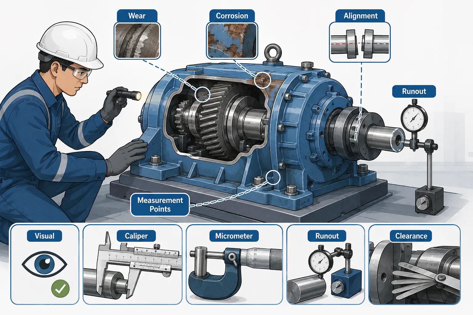
A systematic visual inspection can follow a defined sequence.
Step 1: Establish General Condition
Observe the overall equipment condition.
Step 2: Inspect Structural Areas
Check frames, supports, brackets and foundations.
Step 3: Inspect Connections
Examine bolts, fasteners, welds and joints.
Step 4: Inspect Functional Components
Examine bearings, gears, shafts, seals and couplings.
Step 5: Check for Deterioration
Look for corrosion, wear, cracking and deformation.
Step 6: Identify Abnormal Conditions
Record unusual noise, heat, leakage or movement where relevant.
Step 7: Determine Further Inspection Needs
Identify areas requiring measurement or specialist examination.
Visual Inspection of Structural Components
Structural components should be assessed for:
- Cracking.
- Deformation.
- Corrosion.
- Distortion.
- Loose connections.
- Weld deterioration.
- Damaged supports.
- Foundation movement.
Particular attention should be given to areas carrying significant loads.
Visual Inspection of Rotating Equipment
Rotating machinery should be examined for:
- Leakage.
- Loose components.
- Damaged guards.
- Abnormal wear.
- Coupling condition.
- Bearing housing condition.
- Lubricant leakage.
- Evidence of overheating.
- Unusual surface damage.
Historical vibration information can be useful when interpreting visual findings.
Inspection of Bearings
Bearing inspections may consider:
- Surface condition.
- Lubrication.
- Signs of overheating.
- Wear.
- Contamination.
- Damage.
- Clearance.
- Seating condition.
A bearing that appears visually acceptable may still require dimensional or condition-based assessment.
Inspection of Shafts
Shafts should be examined for:
- Scoring.
- Corrosion.
- Surface damage.
- Cracks.
- Wear.
- Keyway deterioration.
- Thread damage.
- Excessive runout.
Dimensional measurement may be required where wear is suspected.
Inspection of Gears
Gear inspection should consider:
- Tooth wear.
- Pitting.
- Cracking.
- Scuffing.
- Surface damage.
- Tooth profile condition.
- Lubrication.
- Alignment indicators.
Gear condition should be evaluated in relation to operating load and historical performance.
Inspection of Couplings
Couplings should be examined for:
- Wear.
- Cracking.
- Damage.
- Loose components.
- Incorrect assembly.
- Alignment indicators.
- Fastener condition.
Coupling condition can influence rotating-equipment reliability.
Inspection of Welded Components
Visual examination of welds may identify:
- Surface cracking.
- Undercut.
- Excessive surface irregularity.
- Porosity indications.
- Arc strikes.
- Corrosion.
- Incomplete surface finishing.
Where visual findings indicate potential internal or subsurface defects, an appropriate additional inspection method may be required.
Inspection of Bolted Connections
Inspectors should examine:
- Fastener presence.
- Nut condition.
- Thread condition.
- Evidence of loosening.
- Corrosion.
- Washer condition.
- Joint movement.
Where torque requirements apply, suitable controlled measurement or verification procedures should be followed.
Precision Measurement in Mechanical Inspection
Visual inspection alone cannot establish dimensional conformity. Precision measurement is therefore essential for components where small dimensional deviations can affect function.
Common measurements include:
- Diameter.
- Length.
- Thickness.
- Depth.
- Width.
- Bore size.
- Clearance.
- Runout.
- Flatness.
- Alignment.
- Parallelism.
- Perpendicularity.
Vernier Calipers
Vernier calipers are versatile measurement instruments suitable for many mechanical applications.
They can be used for:
- External dimensions.
- Internal dimensions.
- Depth measurements.
- Step measurements.
Before use, the inspector should ensure:
- The instrument is clean.
- The jaws are undamaged.
- The instrument is suitable for the required accuracy.
- Calibration status is valid.
- Measurement surfaces are clean.
Micrometers
Micrometers provide greater precision than general-purpose calipers for suitable applications.
They may be used to measure:
- Shaft diameter.
- Component thickness.
- Small external dimensions.
The inspector should apply the instrument consistently and avoid excessive measuring force.
Dial Indicators
Dial indicators are useful for detecting small deviations.
Typical applications include:
- Shaft runout.
- Alignment.
- Concentricity-related checks.
- Surface variation.
- Component movement.
The instrument must be correctly mounted and referenced before measurements are taken.
Feeler Gauges
Feeler gauges are used to assess small gaps and clearances.
Applications may include:
- Bearing-related clearances.
- Coupling gaps.
- Mechanical assembly clearances.
- Surface gaps.
The correct blade combination should be selected according to the required measurement.
Steel Rules and Depth Gauges
Steel rules may be suitable for less demanding measurements, while depth gauges provide greater control for specific applications.
The instrument should always be selected according to required accuracy.
Bore Gauges
Bore gauges can be used to evaluate internal dimensions.
They may help identify:
- Bore wear.
- Taper.
- Out-of-round conditions.
- Internal dimensional deviation.
Such measurements are particularly important for precision mechanical assemblies.
Surface Measurement
Surface condition may be assessed through:
- Visual examination.
- Surface comparison.
- Roughness measurement where specified.
- Dimensional measurement.
Surface defects can affect sealing, bearing performance, friction, fatigue resistance and component fit.
Measuring Component Wear
Wear should be evaluated by comparing current measurements against:
- Original dimensions.
- Approved drawings.
- Manufacturer requirements.
- Defined wear limits.
- Previous inspection measurements.
A single measurement may show condition, but trend data can demonstrate deterioration.
Measuring Shaft Diameter
A shaft diameter measurement should be taken at appropriate locations.
Where wear is suspected, measurements may be taken:
- At multiple axial positions.
- At multiple orientations.
- At known bearing locations.
- At coupling interfaces.
This can identify:
- Local wear.
- Taper.
- Out-of-roundness.
- Uneven deterioration.
Checking Runout
Runout is particularly important for rotating components.
A typical controlled measurement process involves:
- Secure the measurement instrument.
- Position the indicator correctly.
- Establish the reference.
- Rotate the component under controlled conditions.
- Record the indicator variation.
- Compare the result with the applicable requirement.
Checking Alignment
Alignment inspection may involve:
- Shaft alignment.
- Coupling alignment.
- Parallel alignment.
- Angular alignment.
Poor alignment can contribute to:
- Bearing wear.
- Coupling damage.
- Vibration.
- Seal failure.
- Shaft loading.
Measuring Clearances
Clearance is the intentional or required gap between components.
Examples include:
- Bearing clearance.
- Gear clearance.
- Seal clearance.
- Mechanical assembly clearance.
Incorrect clearance can affect equipment performance significantly.
Dimensional Inspection Procedure
A controlled dimensional inspection should generally follow:
Step 1: Review the Requirement
Identify the specified dimension and tolerance.
Step 2: Select the Instrument
Choose an instrument appropriate to the required accuracy.
Step 3: Verify Calibration
Confirm that the instrument is within its valid calibration status.
Step 4: Prepare the Component
Clean measurement surfaces and remove contamination where appropriate.
Step 5: Position the Instrument
Apply the instrument correctly.
Step 6: Take the Measurement
Use a consistent technique.
Step 7: Repeat Where Necessary
Take additional readings where variation is important.
Step 8: Record Results
Document the actual measurement.
Step 9: Compare With Acceptance Criteria
Determine conformity.
Step 10: Report Deviations
Escalate unacceptable results through the appropriate QA/QC process.
Measurement Accuracy
Accuracy refers to how closely a measurement represents the actual value.
Inspection quality can be affected by:
- Instrument condition.
- Calibration.
- Operator technique.
- Temperature.
- Surface cleanliness.
- Instrument resolution.
- Measurement positioning.
- Environmental conditions.
Therefore, accurate measurement requires control of the complete measurement process.
Calibration Control
Measurement instruments used for quality decisions should have appropriate calibration control.
The inspector should confirm:
- Instrument identification.
- Calibration status.
- Calibration expiry.
- Applicable measurement range.
- Instrument condition.
An instrument with questionable calibration status should not be relied upon for critical acceptance decisions.
Measurement Uncertainty
Measurement results have limitations.
Potential sources include:
- Instrument resolution.
- Operator technique.
- Environmental conditions.
- Surface condition.
- Instrument alignment.
- Repeatability.
Where measurement accuracy is critical, these factors should be considered when interpreting results.
Comparing Measurement Results With Tolerances
Suppose a shaft is specified as:
50.00 ± 0.02 mm
The acceptable range is:
49.98 mm to 50.02 mm
If the measured diameter is 50.01 mm, it falls within the stated tolerance.
If the measured diameter is 50.05 mm, it exceeds the specified range and requires appropriate evaluation.
Measurement Recording
A professional inspection record should include:
- Equipment identification.
- Component identification.
- Measurement location.
- Required dimension.
- Tolerance.
- Actual result.
- Instrument identification.
- Inspector.
- Date.
- Inspection status.
This provides traceable evidence.
Practical Example: Pump Shaft Inspection
A pump has experienced repeated bearing problems.
The inspection includes:
- Visual shaft examination.
- Shaft diameter measurement.
- Runout measurement.
- Coupling inspection.
- Bearing-seat inspection.
A micrometer is used to measure the shaft at multiple positions.
The results show a reduction in diameter at one bearing location.
This finding supports further investigation into shaft wear and bearing alignment.
Practical Example: Gearbox Inspection
A gearbox is opened for inspection following abnormal operating noise.
The inspector examines:
- Gear teeth.
- Bearings.
- Shafts.
- Lubricant condition.
- Housing.
Measurements are taken where wear is suspected.
The results are compared with specified requirements and historical inspection data.
The findings indicate localised gear-tooth wear requiring engineering evaluation.
Practical Example: Heavy Machinery Frame
A heavy machine exhibits increased vibration.
The inspection team examines:
- Structural frame.
- Welded joints.
- Anchor points.
- Bolted connections.
- Foundation.
Visual inspection identifies minor corrosion around one support.
Dimensional checks and alignment measurements are then performed to determine whether movement or deformation has occurred.
Practical Example: Precision Component
A precision-machined component must be verified before assembly.
The inspector checks:
- Overall diameter.
- Bore diameter.
- Length.
- Surface condition.
- Flatness.
Calipers provide general measurements while a micrometer is used for critical external dimensions.
Results are recorded against the approved dimensional requirements.
Inspection of Heavy Machinery Foundations
Machinery foundations can influence alignment and vibration.
Inspectors should look for:
- Cracking.
- Settlement.
- Loose anchor bolts.
- Corrosion.
- Surface damage.
- Movement indicators.
Where required, dimensional or alignment checks should supplement visual examination.
Inspection of Hydraulic and Pneumatic Mechanical Systems
Mechanical inspection may also involve:
- Cylinders.
- Rods.
- Seals.
- Hoses.
- Connections.
- Valves.
- Mountings.
Visual inspection should identify:
- Leakage.
- Surface damage.
- Corrosion.
- Deformation.
- Loose connections.
Physical measurements may be required for critical dimensions.
Inspection of Seals
Seals should be checked for:
- Leakage.
- Wear.
- Cracking.
- Deformation.
- Incorrect seating.
- Surface damage.
Seal condition should be considered alongside operating temperature, pressure and fluid characteristics.
Inspection of Piping Connections
Mechanical inspection of piping-related assemblies may include:
- Flanges.
- Bolted connections.
- Supports.
- Valves.
- Expansion arrangements.
Inspectors should identify:
- Leakage.
- Corrosion.
- Damaged bolts.
- Distortion.
- Support problems.
Inspection of Flanges
Flange inspection can include:
- Face condition.
- Corrosion.
- Damage.
- Flatness.
- Bolt condition.
- Alignment.
Poor flange condition can affect sealing performance.
Inspection of Precision Assemblies
Precision assemblies require greater control because small deviations can affect functionality.
The inspection process should consider:
- Component dimensions.
- Fit.
- Clearances.
- Alignment.
- Surface finish.
- Concentricity.
- Assembly condition.
Measurement tools should be selected according to the required tolerance.
Inspection Tool Selection
Tool selection should be based on:
- Required accuracy.
- Measurement range.
- Component geometry.
- Accessibility.
- Environmental conditions.
- Applicable procedure.
A tool that cannot achieve the required accuracy should not be used for critical acceptance decisions.
Common Inspection Tools
Mechanical inspectors may use:
- Vernier calipers.
- Micrometers.
- Dial indicators.
- Feeler gauges.
- Depth gauges.
- Bore gauges.
- Steel rules.
- Straightedges.
- Levels.
- Torque-related tools where specified.
- Visual aids.
- Measuring tapes for less critical dimensions.
Inspection Sequence for Heavy Machinery
A comprehensive inspection may follow:
Equipment Identification → Safety Preparation → Visual Examination → Component Examination → Dimensional Checks → Functional Assessment → Recording → Evaluation → Reporting
The sequence may be adapted according to equipment type and inspection procedure.
Safety During Physical Inspection
Physical inspection of heavy machinery requires appropriate safety controls.
Before inspection:
- Confirm equipment status.
- Control hazardous energy.
- Establish isolation where required.
- Confirm stored energy has been controlled.
- Establish safe access.
- Use appropriate PPE.
- Maintain communication.
- Prevent unexpected movement.
Inspection quality cannot be separated from safe inspection execution.
Managing Measurement Contamination
Dirt, oil, corrosion products and other contamination can affect measurement results.
Therefore:
- Clean relevant surfaces.
- Remove loose contamination.
- Avoid damaging surfaces.
- Use suitable cleaning methods.
- Ensure measurement surfaces are stable.
Repeatability of Measurements
Where a measurement is critical, repeated readings may be appropriate.
Repeat measurements can help identify:
- Operator variation.
- Surface irregularities.
- Instrument instability.
- Localised wear.
Significant differences between readings should be investigated.
Identifying Non-Conformances
A non-conformance may occur when:
- A dimension exceeds tolerance.
- A component is damaged.
- A required feature is missing.
- A defect exceeds acceptance criteria.
- Equipment condition is unsuitable.
- Inspection evidence is incomplete.
The finding should be documented objectively.
Objective Inspection Reporting
Avoid statements such as:
“Component looks bad.”
Use objective descriptions such as:
“Measured shaft diameter at bearing seat was below the specified minimum dimension.”
Objective reporting improves technical decision-making.
Inspection Evidence
Reliable evidence may include:
- Measurements.
- Photographs.
- Inspection records.
- Instrument identification.
- Calibration status.
- Defect location.
- Condition descriptions.
- Comparison against requirements.
Evidence should be traceable to the inspected component.
Integrating Inspection With QA/QC
Inspection results should feed into the broader QA/QC system.
Relevant outputs may include:
- Inspection reports.
- NCRs.
- Corrective actions.
- Repair recommendations.
- Re-inspection requirements.
- Maintenance notifications.
This creates a feedback loop between inspection and quality management.
Integrating Inspection With Maintenance
Inspection findings can support maintenance planning.
For example:
Wear identified → Condition assessed → Maintenance priority established → Repair planned → Post-repair inspection
This reduces the risk of uncontrolled deterioration.
Benefits of Thorough Visual and Physical Inspection
Safety Benefits
- Early identification of dangerous deterioration.
- Improved mechanical integrity.
- Better identification of damaged components.
- Reduced probability of unexpected mechanical failure.
Quality Benefits
- Improved conformity verification.
- Better dimensional control.
- Reduced installation errors.
- Stronger traceability.
Reliability Benefits
- Early detection of wear.
- Better maintenance planning.
- Reduced recurring failures.
- Improved equipment availability.
Financial Benefits
- Reduced emergency repairs.
- Reduced rework.
- Better component replacement decisions.
- Lower lifecycle costs.
Operational Benefits
- Better equipment condition visibility.
- Improved maintenance scheduling.
- Reduced unplanned downtime.
- More predictable performance.
Common Inspection Errors
Inspectors should avoid:
- Using unsuitable instruments.
- Using instruments without valid calibration.
- Measuring contaminated surfaces.
- Recording approximate values instead of actual readings.
- Ignoring tolerances.
- Relying only on visual examination.
- Failing to inspect critical areas.
- Ignoring historical findings.
- Failing to identify the exact measurement location.
- Reporting subjective observations.
- Failing to escalate significant deviations.
Professional Inspection Checklist
Before Inspection
- Confirm equipment identification.
- Review inspection requirements.
- Review previous findings.
- Confirm applicable drawings.
- Verify tool availability.
- Check calibration status.
- Establish safe inspection conditions.
During Visual Inspection
- Examine overall condition.
- Check structural components.
- Inspect connections.
- Examine rotating components.
- Check for corrosion.
- Identify wear.
- Look for leakage.
- Record abnormal findings.
During Measurement
- Select suitable instrument.
- Confirm calibration.
- Clean measurement surface.
- Establish measurement location.
- Take accurate readings.
- Repeat where required.
- Record actual values.
- Compare against tolerances.
After Inspection
- Review findings.
- Identify non-conformances.
- Confirm records are complete.
- Recommend further examination where required.
- Communicate significant findings.
- Initiate corrective action where appropriate.
- Update inspection history.
Case Study: Comprehensive Inspection of a Critical Compressor
Background
A large industrial compressor has been operating continuously and has recently shown increased vibration and temperature.
The machine is critical to production, making inspection quality particularly important.
Pre-Inspection Information
The team reviews:
- Equipment drawings.
- Operating parameters.
- Maintenance history.
- Previous inspection reports.
- Vibration trends.
- Manufacturer information.
Visual Inspection
The inspection identifies:
- Minor lubricant leakage.
- Surface contamination.
- Evidence of localised overheating.
- Slight deterioration around a coupling area.
Physical Measurements
The team performs:
- Shaft measurements.
- Coupling alignment checks.
- Bearing clearance checks.
- Runout measurement.
Findings
One measurement indicates a dimensional deviation from the defined requirement.
The inspection team records:
- Exact location.
- Required dimension.
- Actual dimension.
- Instrument used.
- Calibration status.
Engineering Evaluation
The finding is compared with historical data and operating conditions.
Further investigation identifies a developing alignment problem.
Corrective Action
The organisation:
- Corrects alignment.
- Addresses the affected component.
- Repeats critical measurements.
- Reviews vibration.
- Updates the maintenance plan.
Case Study Lessons
The case demonstrates the value of combining:
- Visual examination.
- Precision measurement.
- Historical data.
- Equipment knowledge.
- Objective reporting.
- Corrective action.
Key Takeaways
Thorough mechanical inspection should:
- Begin with proper preparation.
- Confirm equipment identity.
- Understand inspection requirements.
- Use systematic visual examination.
- Identify deterioration mechanisms.
- Use appropriate physical measurement.
- Select tools according to required accuracy.
- Verify instrument calibration.
- Control measurement conditions.
- Record actual measurements.
- Compare results with defined tolerances.
- Identify non-conformances objectively.
- Maintain traceability.
- Integrate inspection findings with QA/QC.
- Support maintenance decisions.
- Escalate significant deviations.
- Verify corrective actions.
Conclusion
Executing thorough visual and physical inspections requires a structured combination of observation, measurement, technical judgement, documentation, and quality control. Visual examination provides valuable information about the condition of heavy machinery and precision components, while physical measurement establishes objective evidence about dimensions, clearances, alignment, runout, wear, and conformity. The effectiveness of the inspection depends heavily on selecting appropriate tools, maintaining calibration, controlling measurement conditions, applying consistent techniques, and comparing results against approved requirements.
For heavy machinery, the inspection process should consider the complete mechanical system rather than isolated components. Bearings, shafts, gears, couplings, seals, structural supports, foundations, bolted connections, welded areas, and pressure-containing components can interact with one another, meaning that a defect in one area may contribute to deterioration elsewhere. Combining visual evidence with precise measurements and historical performance information enables inspectors to identify developing problems before they become major failures.
A professional mechanical inspection also creates valuable evidence for the wider QA/QC and asset-integrity system. Accurate records allow inspection findings to be compared over time, support maintenance prioritisation, provide traceability for engineering decisions, and establish a documented basis for corrective action. When inspection teams consistently use calibrated instruments, objective acceptance criteria, controlled procedures, and clear reporting practices, organisations can improve defect detection, reduce rework, strengthen mechanical integrity, increase equipment reliability, and minimise unexpected downtime. This makes comprehensive visual and physical inspection an essential component of safe, reliable, and high-quality mechanical engineering operations.
3: Interpret Engineering Drawings, Manufacturing Tolerances, and Data Sheets to Verify That Fabricated Mechanical Parts Match Exact Design Requirements
Engineering drawings, manufacturing tolerances, and technical data sheets provide the controlled technical information needed to determine whether fabricated mechanical components conform to their intended design requirements. In mechanical engineering quality assurance and quality control, dimensional inspection alone is not sufficient because a component can have dimensions that appear correct while still failing other important requirements such as material grade, surface finish, geometric accuracy, hole position, thread specification, heat treatment, weld details, or functional tolerances. Professional verification therefore requires inspectors to interpret engineering information accurately and compare the fabricated component against the complete set of applicable technical requirements.
The ability to interpret engineering drawings is particularly important when inspecting precision components, fabricated assemblies, pressure-containing equipment, rotating machinery, structural mechanical parts, shafts, flanges, brackets, housings, gears, couplings, and machined components. Drawings communicate geometry, dimensions, tolerances, datums, materials, surface requirements, symbols, manufacturing details, and revision status. Data sheets provide complementary information such as operating conditions, equipment ratings, materials, performance requirements, and design parameters. When these sources are correctly interpreted and linked with actual inspection measurements, QA/QC personnel can establish objective evidence of conformity, identify deviations, prevent incorrect components from entering assembly or service, and support reliable mechanical system performance.
Understanding the Purpose of Engineering Drawings
An engineering drawing is a controlled technical representation of a component, assembly, or system. It communicates design intent through graphical information, dimensions, notes, symbols, specifications, and references.
A mechanical drawing may communicate:
- Component geometry.
- Overall dimensions.
- Feature dimensions.
- Hole locations.
- Material requirements.
- Surface finishes.
- Tolerances.
- Geometric controls.
- Welding requirements.
- Thread specifications.
- Assembly relationships.
- Datums.
- Section details.
- Manufacturing notes.
- Revision information.
The drawing should therefore be treated as a controlled engineering document rather than simply a picture of the component.
Why Drawing Interpretation Matters in QA/QC
Incorrect interpretation of a drawing can result in:
- Incorrect component dimensions.
- Wrong material selection.
- Incorrect hole positions.
- Improper assembly.
- Excessive clearances.
- Insufficient clearances.
- Incorrect surface finish.
- Manufacturing rework.
- Installation difficulties.
- Equipment malfunction.
- Mechanical failure.
Professional inspection requires the inspector to understand exactly what the drawing requires before deciding whether the fabricated component is acceptable.
Key Definitions and Concepts
| Term | Definition | Mechanical QA/QC Application |
|---|---|---|
| Engineering Drawing | Controlled graphical representation of a component or assembly | Verifying fabricated geometry |
| Design Intent | Functional and dimensional purpose established by the designer | Determining required component characteristics |
| Dimension | Numerical value defining size or location | Checking length, diameter or spacing |
| Tolerance | Permitted variation from a specified dimension | Determining dimensional acceptance |
| Nominal Dimension | Target or stated design dimension | Comparing actual measurement with design value |
| Datum | Reference feature used to establish measurement or geometric relationships | Controlling component orientation |
| Geometric Tolerance | Controlled variation in form, orientation, location or runout | Checking flatness or concentricity |
| Surface Finish | Required condition or roughness of a surface | Verifying machined sealing surfaces |
| Material Specification | Defined material requirement for a component | Confirming material grade |
| Data Sheet | Technical document containing equipment or component information | Verifying rated and design characteristics |
| Revision | Controlled version of a technical document | Ensuring current requirements are used |
| Bill of Materials | Structured list of required components and materials | Checking component identity |
| Feature | Specific geometric element of a component | Hole, groove, thread or slot |
| Clearance | Designed space between interacting components | Verifying assembly fit |
| Fit | Relationship between mating components | Checking shaft and bore compatibility |
| Conformance | Compliance with specified requirements | Accepting fabricated components |
| Non-Conformance | Failure to meet a specified requirement | Raising an NCR |
| Traceability | Ability to link a component to its technical and inspection records | Controlling fabricated parts |
| Revision Control | System for ensuring current approved documents are used | Preventing obsolete drawing use |
Controlled Drawing Information
Before beginning inspection, the inspector should confirm that the drawing is:
- Approved.
- Current.
- Applicable to the component.
- Correctly identified.
- At the appropriate revision.
- Legible.
- Complete.
Particular attention should be given to:
- Drawing number.
- Revision number.
- Component identification.
- Material specification.
- General notes.
- Special notes.
- Applicable standards.
- Tolerances.
- Drawing references.
Using an obsolete drawing can result in incorrect acceptance decisions.
Drawing Number and Component Identification
The drawing number should correspond with the component under inspection.
The inspector should verify:
- Part number.
- Drawing number.
- Component description.
- Assembly reference.
- Revision.
- Purchase or work order reference.
This establishes traceability between the physical component and its design information.
Understanding Drawing Views
Mechanical drawings commonly use multiple views to communicate three-dimensional geometry.
Typical views include:
- Front view.
- Top view.
- Side view.
- Section view.
- Detail view.
- Auxiliary view.
The inspector should understand how these views relate to each other.
Sectional Views
Sectional views are particularly useful for showing internal features.
They may reveal:
- Internal bores.
- Wall thickness.
- Internal grooves.
- Threads.
- Cavities.
- Internal passages.
- Hidden interfaces.
A component that appears correct externally may contain internal features that fail the drawing requirements.
Detail Views
Detail views provide enlarged information about complex areas.
They may define:
- Small holes.
- Threads.
- Grooves.
- Weld details.
- Chamfers.
- Fillets.
- Surface requirements.
Inspectors should ensure detail views are not overlooked.
Dimensions and Measurement
Dimensions communicate the required size or location of a feature.
Common dimensions include:
- Length.
- Width.
- Height.
- Diameter.
- Radius.
- Angle.
- Depth.
- Thickness.
- Hole spacing.
The inspector compares actual measurements against these specified values.
Nominal Dimensions
A nominal dimension represents the intended design value.
For example:
50.00 mm
If a tolerance is also provided, the acceptable range is determined from the tolerance.
Understanding Tolerances
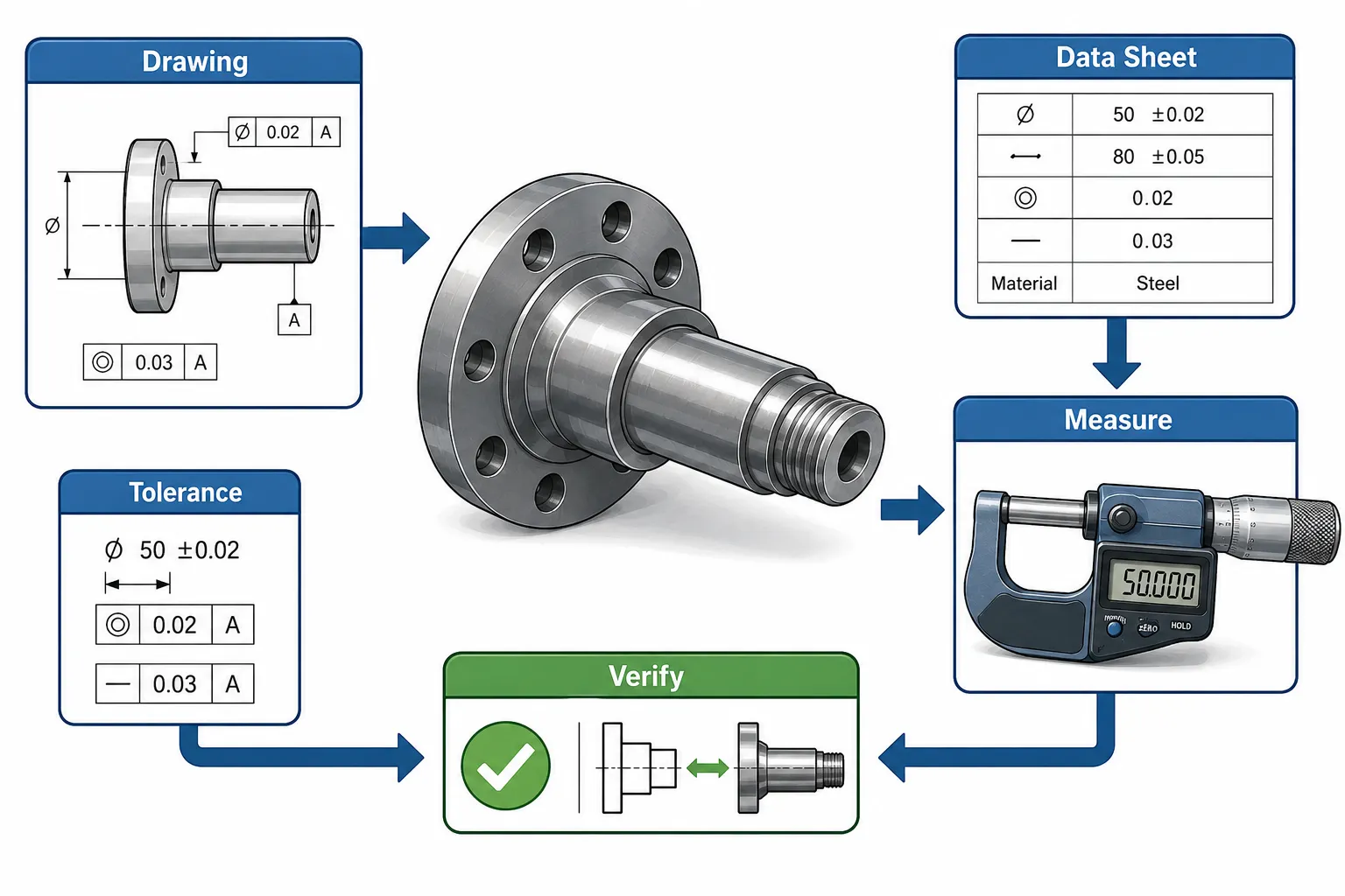
Manufacturing processes cannot generally produce every component at exactly one numerical value. Tolerances define acceptable variation.
For example:
50.00 ± 0.02 mm
means the component may be between:
49.98 mm and 50.02 mm
A measured value of 50.01 mm therefore conforms to the dimensional requirement.
Bilateral Tolerance
A bilateral tolerance allows variation in both directions.
Example:
25.00 ± 0.05 mm
Acceptable range:
24.95–25.05 mm
Unilateral Tolerance
A unilateral tolerance permits variation in one direction.
Example:
40.00 +0.00 / -0.03 mm
Acceptable range:
39.97–40.00 mm
The inspector must understand the tolerance notation before making an acceptance decision.
Limits of Size
Some drawings provide maximum and minimum limits rather than a nominal dimension with ± tolerance.
For example:
- Maximum: 60.05 mm.
- Minimum: 59.98 mm.
Any measurement within this range conforms to the dimensional requirement.
General Tolerances
Drawings may specify general tolerances that apply to dimensions where individual tolerances are not separately stated.
The inspector should identify:
- Applicable general tolerance standard.
- Drawing note.
- Dimension category.
- Whether a specific tolerance overrides the general requirement.
Geometric Dimensioning and Tolerancing
Geometric controls specify how features must relate to one another rather than simply specifying their size.
They may control:
- Form.
- Orientation.
- Location.
- Runout.
Examples include:
- Straightness.
- Flatness.
- Circularity.
- Cylindricity.
- Parallelism.
- Perpendicularity.
- Position.
- Concentricity-related requirements.
- Runout.
Datum Systems
Datums provide reference points, lines, planes, or axes from which measurements are established.
A component may use:
- Primary datum.
- Secondary datum.
- Tertiary datum.
The correct datum sequence is important because measurements can change depending on the reference system.
Why Datums Matter
Consider a machined mounting plate containing multiple holes. Measuring the hole locations from an arbitrary edge may produce apparently acceptable results, while measuring them from the specified datum may reveal that the pattern is incorrectly positioned.
Therefore:
Correct Measurement Reference = Correct Conformance Decision
Flatness
Flatness controls the variation of a surface from an ideal plane.
It can be important for:
- Flanges.
- Mounting surfaces.
- Machine bases.
- Sealing surfaces.
- Precision assemblies.
A surface may have the correct overall thickness but still fail a flatness requirement.
Parallelism
Parallelism controls the relationship between two surfaces, lines or features.
It may be important where components must maintain consistent spacing or alignment.
Perpendicularity
Perpendicularity controls whether a feature is correctly oriented relative to a reference.
It can be important for:
- Shafts.
- Mounting holes.
- Machine faces.
- Structural components.
Position Tolerance
Position requirements control the location of features such as holes.
For example, a hole may have the correct diameter but still be incorrectly positioned.
Therefore, dimensional verification must consider both:
- Feature size.
- Feature location.
Runout
Runout controls variation of a rotating feature relative to a reference axis.
It is particularly important for:
- Shafts.
- Rotors.
- Flanges.
- Rotating discs.
Excessive runout can contribute to:
- Vibration.
- Seal problems.
- Bearing loading.
- Coupling problems.
Surface Finish Requirements
Surface finish can influence:
- Sealing.
- Friction.
- Wear.
- Fatigue.
- Lubrication.
- Component fit.
A fabricated component may meet dimensional requirements but still fail because its surface finish does not meet the drawing requirement.
Threads and Thread Specifications
Threaded components should be checked against the applicable requirements.
Important characteristics include:
- Thread size.
- Pitch.
- Thread form.
- Thread direction.
- Thread length.
- Thread class or fit.
- Surface condition.
The correct thread specification must be verified rather than assumed from appearance.
Hole Requirements
Hole inspection may involve:
- Diameter.
- Depth.
- Location.
- Spacing.
- Orientation.
- Counterbore.
- Countersink.
- Threading.
A hole can therefore be dimensionally correct in one respect while failing another requirement.
Chamfers and Fillets
Small geometric features can have functional importance.
Chamfers may support:
- Assembly.
- Edge protection.
- Component insertion.
Fillets may influence:
- Stress concentration.
- Machining.
- Component fit.
These features should be verified where specified.
Material Verification
Engineering drawings and data sheets may specify required materials.
Verification may involve:
- Material certificates.
- Identification markings.
- Traceability records.
- Procurement documentation.
- Material testing where required.
Material compliance is essential because incorrect material properties can compromise mechanical performance.
Data Sheets
Technical data sheets provide information about equipment or components.
They may include:
- Model.
- Capacity.
- Pressure.
- Temperature.
- Speed.
- Power.
- Material.
- Dimensions.
- Performance requirements.
- Operating limits.
Data sheets should be reviewed alongside drawings and specifications.
Drawing Versus Data Sheet
The drawing usually provides detailed geometry and fabrication requirements, while the data sheet often provides equipment-level technical and operational information.
For example:
Drawing → Geometry, dimensions, tolerances
Data Sheet → Rating, capacity, operating conditions
Both may be necessary to establish complete conformity.
Manufacturing Tolerances and Functional Requirements
Tolerances are not simply manufacturing conveniences. They often reflect functional requirements.
For example:
- Bearing clearance affects lubrication and rotation.
- Shaft diameter affects fit.
- Hole position affects assembly.
- Surface finish affects sealing.
- Gear dimensions affect transmission.
- Alignment affects vibration.
Therefore, tolerance verification should always be considered in relation to component function.
Fit Between Mating Components
Mechanical components may require specific fits.
Examples include:
- Shaft and bearing.
- Shaft and coupling.
- Pin and hole.
- Bush and housing.
- Gear and shaft.
The inspector should verify both mating dimensions where necessary.
Inspection Equipment for Drawing Verification
Common instruments include:
- Vernier calipers.
- Micrometers.
- Bore gauges.
- Height gauges.
- Dial indicators.
- Feeler gauges.
- Thread gauges.
- Radius gauges.
- Surface measurement instruments.
- Coordinate measuring equipment where appropriate.
Instrument selection must reflect the required tolerance.
Measurement Instrument Selection
If a drawing requires high precision, a general-purpose measuring tool may not provide sufficient accuracy.
Selection should consider:
- Required tolerance.
- Instrument resolution.
- Measurement range.
- Feature geometry.
- Accessibility.
- Calibration status.
Drawing Interpretation Procedure
Step 1: Identify the Drawing
Confirm drawing number, component and revision.
Step 2: Review General Notes
Identify applicable standards and general requirements.
Step 3: Identify Critical Features
Highlight dimensions, tolerances and functional features.
Step 4: Establish Datums
Determine the reference system.
Step 5: Identify Material Requirements
Verify material grade and associated documentation.
Step 6: Review Geometric Requirements
Identify flatness, orientation, location and runout controls.
Step 7: Review Surface Requirements
Identify surface-finish and treatment requirements.
Step 8: Select Measurement Methods
Match instruments to required accuracy.
Step 9: Measure the Component
Record actual results.
Step 10: Compare Against Requirements
Determine conformity.
Step 11: Record Deviations
Document non-conforming conditions objectively.
Step 12: Complete Inspection Records
Maintain traceability.
Step-by-Step Dimensional Verification
A professional verification process can follow:
Drawing Review → Feature Identification → Datum Establishment → Instrument Selection → Measurement → Comparison → Conformance Decision → Documentation
This creates a repeatable inspection process.
Example: Shaft Verification
A drawing specifies:
- Diameter: 50.00 mm.
- Tolerance: ±0.02 mm.
- Length: 300 mm.
- Runout: Defined limit.
The inspector:
- Confirms drawing revision.
- Identifies shaft datum.
- Checks micrometer calibration.
- Measures diameter at multiple locations.
- Checks runout with a dial indicator.
- Records results.
- Compares them against requirements.
If diameter and runout comply, the shaft can proceed subject to all other requirements being satisfied.
Example: Mounting Plate
A fabricated mounting plate contains several bolt holes.
The drawing specifies:
- Plate thickness.
- Overall dimensions.
- Hole diameter.
- Hole position.
- Flatness.
The inspector measures each requirement.
Even if the hole diameters are correct, the component may still fail if hole positions are outside the specified tolerance.
Example: Flange
A flange drawing specifies:
- Outside diameter.
- Bolt-circle diameter.
- Hole diameter.
- Thickness.
- Face flatness.
- Surface finish.
The inspection must address all relevant characteristics rather than measuring only the flange diameter.
Example: Gear
A gear drawing may specify:
- Number of teeth.
- Pitch-related characteristics.
- Bore diameter.
- Face width.
- Material.
- Surface condition.
Verification therefore combines dimensional inspection with material and manufacturing records.
Example: Precision Housing
A precision-machined housing may contain several bores that must remain aligned.
Inspection may include:
- Bore diameter.
- Bore location.
- Concentricity-related controls.
- Surface finish.
- Overall dimensions.
A housing can have correct individual bore diameters but still fail if the bores are incorrectly positioned relative to one another.
Revision Control
Revision control is critical.
Before inspection, confirm:
- Current revision.
- Approved status.
- Effective date where applicable.
- Associated specification.
- Applicable change notes.
Inspectors should not use outdated drawings.
Drawing Changes
A revised drawing may change:
- Dimension.
- Tolerance.
- Material.
- Surface finish.
- Hole location.
- Manufacturing process.
- Acceptance criteria.
The inspection team must understand whether the physical component was manufactured before or after the revision.
Handling Drawing Ambiguity
If a drawing is unclear, the inspector should not make assumptions.
Appropriate action includes:
- Review related documentation.
- Consult engineering.
- Confirm the approved specification.
- Obtain clarification.
- Document the resolution.
An unresolved ambiguity should not become an undocumented acceptance decision.
Data Sheet Verification
A data sheet may specify:
- Rated speed.
- Flow.
- Pressure.
- Temperature.
- Power.
- Material.
- Dimensions.
- Performance.
The inspector should compare relevant information with the fabricated or assembled equipment.
Cross-Checking Technical Documents
A robust verification process may require comparison between:
- Engineering drawing.
- Data sheet.
- Material certificate.
- Purchase specification.
- Manufacturing record.
- Inspection report.
- Test certificate.
Differences should be investigated rather than ignored.
Traceability of Fabricated Parts
Traceability may include:
- Part number.
- Drawing number.
- Material heat number.
- Batch number.
- Manufacturing order.
- Inspection record.
- Inspector identification.
Traceability provides confidence that the inspected component corresponds to the required design.
Non-Conformance Identification
A non-conformance may occur when:
- Dimension exceeds tolerance.
- Material does not match specification.
- Surface finish is unacceptable.
- Hole location is incorrect.
- Geometric tolerance is exceeded.
- Wrong revision was used.
- Required feature is missing.
The deviation should be recorded accurately.
Deviation Assessment
Not every deviation has the same functional consequence.
Engineering evaluation may consider:
- Magnitude of deviation.
- Component function.
- Safety significance.
- Assembly impact.
- Mechanical loading.
- Future reliability.
A deviation should be formally evaluated rather than informally accepted.
Practical QA/QC Reporting
A strong inspection record should identify:
- Requirement.
- Actual result.
- Measurement method.
- Instrument.
- Calibration status.
- Acceptance criterion.
- Conformance status.
Example:
| Feature | Requirement | Actual | Status |
|---|---|---|---|
| Shaft diameter | 50.00 ± 0.02 mm | 50.01 mm | Conforming |
| Shaft length | 300 ± 0.10 mm | 300.04 mm | Conforming |
| Hole diameter | 20.00 ± 0.03 mm | 20.06 mm | Non-conforming |
| Surface finish | Specified limit | Above limit | Non-conforming |
Quality Control Benefits
Accurate drawing interpretation supports:
- Reduced fabrication errors.
- Better dimensional control.
- Improved assembly quality.
- Reduced rework.
- Better material traceability.
- More reliable equipment.
- Stronger inspection evidence.
- Better supplier control.
Operational Benefits
Correctly fabricated components can provide:
- Improved equipment fit.
- Reduced vibration.
- Better sealing.
- Improved alignment.
- Longer component life.
- Reduced maintenance.
- Improved reliability.
Common Drawing Interpretation Errors
Inspectors should avoid:
- Using obsolete drawings.
- Ignoring revision numbers.
- Measuring from incorrect datums.
- Ignoring geometric tolerances.
- Treating nominal dimensions as exact acceptance limits.
- Ignoring general tolerances.
- Failing to review notes.
- Overlooking sectional views.
- Ignoring surface-finish requirements.
- Assuming material compliance.
- Measuring only the most obvious dimensions.
Common Tolerance Errors
Incorrect approaches include:
- Accepting dimensions outside the stated limits.
- Treating every tolerance as ±.
- Ignoring unilateral tolerances.
- Applying the wrong general tolerance.
- Using an unsuitable measuring instrument.
- Failing to consider measurement uncertainty.
Case Study: Verification of a Precision Pump Shaft
Background
A fabricated shaft is produced for a critical industrial pump. The shaft must fit within bearings and connect to a coupling.
Drawing Requirements
The drawing specifies:
- Shaft diameter.
- Length.
- Keyway dimensions.
- Surface finish.
- Runout.
- Material.
Inspection Process
The QA/QC inspector first verifies:
- Drawing number.
- Revision.
- Part number.
- Material documentation.
The inspector then selects:
- Micrometer.
- Vernier caliper.
- Depth measurement equipment.
- Dial indicator.
Dimensional Findings
The shaft diameter complies at the primary measurement location but shows greater variation at another location.
The inspector performs additional measurements to establish whether the variation represents:
- Localised wear.
- Manufacturing deviation.
- Measurement error.
Runout Verification
A dial indicator is positioned against the shaft while the shaft is rotated under controlled conditions.
The measured runout exceeds the specified requirement.
Engineering Evaluation
The deviation could influence:
- Bearing loading.
- Vibration.
- Seal performance.
- Coupling alignment.
The component is therefore referred for engineering disposition.
Corrective Action
The appropriate action may involve:
- Rework.
- Additional machining.
- Engineering-approved deviation.
- Rejection and replacement.
The decision should be based on documented technical evaluation.
Case Study Lessons
The example demonstrates that conformity depends on more than a single dimension. A component must satisfy the complete set of applicable design requirements.
Integrated Verification Process
A robust mechanical component verification process can be represented as:
Drawing → Data Sheet → Material Records → Manufacturing → Measurement → Comparison → Conformance → Documentation
Each stage contributes to product quality.
Practical Inspection Checklist
Drawing Review
- Confirm drawing number.
- Confirm revision.
- Identify component.
- Review notes.
- Identify datums.
- Identify critical dimensions.
- Identify tolerances.
- Identify geometric controls.
- Review material requirements.
Physical Verification
- Confirm component identity.
- Check material traceability.
- Inspect geometry.
- Measure dimensions.
- Check surface condition.
- Verify hole locations.
- Check threads.
- Verify geometric requirements.
Documentation
- Record actual measurements.
- Record instruments.
- Confirm calibration.
- Record inspector details.
- Identify deviations.
- Raise NCRs where required.
- Maintain traceability.
Key Takeaways
Professional interpretation of engineering drawings and technical data should involve:
- Controlled document verification.
- Correct revision identification.
- Understanding drawing views.
- Accurate interpretation of dimensions.
- Correct application of tolerances.
- Understanding datum systems.
- Verification of geometric requirements.
- Material verification.
- Surface-finish verification.
- Data-sheet comparison.
- Appropriate instrument selection.
- Accurate measurement.
- Objective conformance assessment.
- Traceable documentation.
- Effective non-conformance management.
Conclusion
Interpreting engineering drawings, manufacturing tolerances, and technical data sheets is a core mechanical QA/QC competency because fabricated components must be verified against complete design requirements rather than judged by appearance or isolated dimensional checks. Engineering drawings establish geometry, dimensions, tolerances, datums, materials, surface requirements, and other manufacturing information, while data sheets provide important equipment-level characteristics such as ratings, operating conditions, materials, and performance requirements. Correctly interpreting these sources allows inspection personnel to establish what the component should be before comparing it with what has actually been manufactured.
A professional verification process requires controlled document review, correct revision identification, accurate datum selection, appropriate measurement techniques, calibrated instruments, and objective comparison against acceptance criteria. Inspectors must understand the difference between nominal dimensions, tolerances, limits of size, geometric controls, surface requirements, and functional characteristics. They must also recognise that a component can satisfy one requirement while failing another; for example, a shaft may have the correct diameter but unacceptable runout, or a mounting plate may have correctly sized holes that are incorrectly positioned.
The ultimate purpose of drawing and data-sheet verification is to protect mechanical performance and integrity. Accurate conformity assessment reduces fabrication errors, prevents unsuitable components from entering assembly, reduces rework, supports traceability, and improves equipment reliability. When engineering drawings, material records, manufacturing information, inspection measurements, and QA/QC documentation are integrated into a controlled verification process, mechanical engineering organisations can make defensible acceptance decisions and identify deviations before they develop into operational problems. This provides a strong foundation for quality-controlled manufacturing, reliable mechanical installation, safe commissioning, and long-term mechanical system performance.
4: Document Detailed Inspection Findings and Geometric Variations to Isolate Physical Components That Fail to Meet Baseline Production Targets
Accurate documentation of mechanical inspection findings is a fundamental part of effective QA/QC management because inspection results only provide lasting value when they are recorded in a clear, objective, traceable, and technically defensible form. When mechanical components are inspected against engineering drawings, manufacturing tolerances, production specifications, and approved acceptance criteria, the resulting information must show exactly what was inspected, what was measured, what requirement applied, and whether the component conformed. Detailed documentation is particularly important when geometric variations, dimensional deviations, surface defects, alignment problems, or manufacturing inconsistencies are identified. A well-controlled inspection record allows quality personnel, production engineers, maintenance teams, manufacturing supervisors, and engineering management to distinguish conforming components from those requiring further evaluation, rework, repair, rejection, or formal disposition.
The purpose of documenting inspection findings is not simply to create a record of completed inspection activities. It is to create reliable engineering evidence that supports decisions about product conformity and mechanical integrity. A component may fail a production target because of excessive dimensional variation, incorrect geometry, poor surface condition, incorrect hole location, unacceptable flatness, excessive runout, incorrect material, or another deviation from the approved design. Effective documentation identifies the precise nature and location of the deviation and connects it with the relevant drawing, specification, measurement method, instrument, inspector, date, and acceptance criterion. This enables organisations to isolate defective components before assembly or service, prevent unintended use, identify recurring production problems, strengthen corrective action, and improve the overall effectiveness of the mechanical QA/QC system.
Understanding Inspection Findings and Geometric Variations
An inspection finding is an objective observation or measurement obtained during the examination of a mechanical component or system. It may confirm conformity or identify a deviation from a specified requirement.
Examples include:
- Shaft diameter outside tolerance.
- Excessive shaft runout.
- Incorrect hole position.
- Excessive component flatness deviation.
- Incorrect bore diameter.
- Surface damage.
- Thread defects.
- Weld-related dimensional distortion.
- Incorrect component length.
- Excessive clearance.
- Misalignment.
- Incorrect material identification.
A geometric variation is a difference between the actual physical geometry of a manufactured component and the geometry specified by the design.
Such variations may involve:
- Size.
- Form.
- Orientation.
- Location.
- Profile.
- Runout.
- Alignment.
The significance of a variation depends on the applicable tolerance and the function of the component.
Why Detailed Inspection Documentation Matters
A detailed inspection record creates an evidence trail between design requirements and physical production results.
It enables an organisation to:
- Verify product conformity.
- Isolate defective components.
- Prevent unintended use.
- Support NCR processes.
- Identify recurring defects.
- Analyse manufacturing trends.
- Improve production controls.
- Support corrective actions.
- Demonstrate traceability.
- Provide evidence for audits.
- Support engineering decisions.
Without accurate documentation, even a correctly performed inspection may fail to provide sufficient evidence for subsequent decisions.
Key Definitions and Concepts
| Term | Definition | Application in Mechanical QA/QC |
|---|---|---|
| Inspection Finding | Objective result identified during inspection | Recording dimensional or physical conditions |
| Geometric Variation | Difference between actual geometry and specified geometry | Identifying flatness, runout or position deviations |
| Baseline Production Target | Approved dimensional, quality or performance requirement | Determining whether a component conforms |
| Non-Conformance | Failure to meet an applicable specified requirement | Isolating a defective component |
| Inspection Record | Controlled record of inspection activities and results | Providing traceable evidence |
| Acceptance Criteria | Requirements used to determine conformity | Comparing actual results with limits |
| Traceability | Ability to connect a finding to a specific component and records | Identifying affected parts |
| Measurement Result | Actual value obtained using an inspection instrument | Recording shaft diameter or thickness |
| Tolerance | Permitted variation from a specified requirement | Establishing acceptable dimensional limits |
| Datum | Reference used for geometric measurement | Establishing the correct inspection reference |
| Runout | Variation of a rotating surface relative to a reference axis | Checking shafts and rotating components |
| Flatness | Degree to which a surface conforms to an ideal plane | Checking machined or mounting surfaces |
| Position Variation | Difference between actual and specified feature location | Checking holes and mounting features |
| Rework | Approved activity used to bring a non-conforming component into conformity | Correcting dimensional deviations |
| Repair | Action that restores function but may not fully restore original requirements | Managing acceptable technical dispositions |
| Rejection | Formal decision that a component is unsuitable for intended use | Preventing defective parts from entering production |
| NCR | Controlled record describing a non-conforming condition | Managing production deviations |
Baseline Production Targets
Baseline production targets provide the reference against which manufactured components are assessed.
They may include:
- Dimensional requirements.
- Geometric tolerances.
- Surface-finish requirements.
- Material specifications.
- Assembly requirements.
- Functional characteristics.
- Manufacturing specifications.
- Drawing requirements.
- Customer requirements.
- Approved technical specifications.
The inspector must use the correct baseline because comparing a component against an incorrect or obsolete requirement can result in an invalid acceptance decision.
Establishing the Correct Baseline
Before documenting a finding, confirm:
- Correct drawing number.
- Correct revision.
- Component identification.
- Applicable specification.
- Required dimension.
- Applicable tolerance.
- Geometric requirement.
- Material requirement.
- Inspection method.
- Acceptance criterion.
This prevents incorrect defect classification.
Component Identification and Traceability
A defective component must be physically identifiable.
Identification may include:
- Part number.
- Serial number.
- Batch number.
- Heat number.
- Work order.
- Manufacturing order.
- Equipment number.
- Location.
- Inspection tag.
Where components are similar, identification becomes particularly important.
For example, if ten identical shafts are manufactured and two fail dimensional inspection, the two defective shafts must be clearly isolated and traceable.
Physical Isolation of Non-Conforming Components
Documentation should support physical segregation where required.
Possible controls include:
- Non-conforming product tags.
- Quarantine areas.
- Identification labels.
- Hold status.
- Controlled storage.
- Digital status records.
The objective is to prevent an unacceptable component from being accidentally installed or released.
Inspection Finding Categories
Inspection findings may generally be classified as:
Conforming
The component meets the specified requirement.
Minor Deviation
A deviation exists but may require engineering evaluation depending on the applicable criteria.
Non-Conforming
The component fails a defined requirement.
Requires Further Investigation
Available evidence is insufficient to make a final decision.
Critical Finding
The condition has significant potential implications for mechanical integrity, safety, or functionality and requires immediate escalation.
Classification should be based on documented requirements rather than personal preference.
Documenting Dimensional Findings
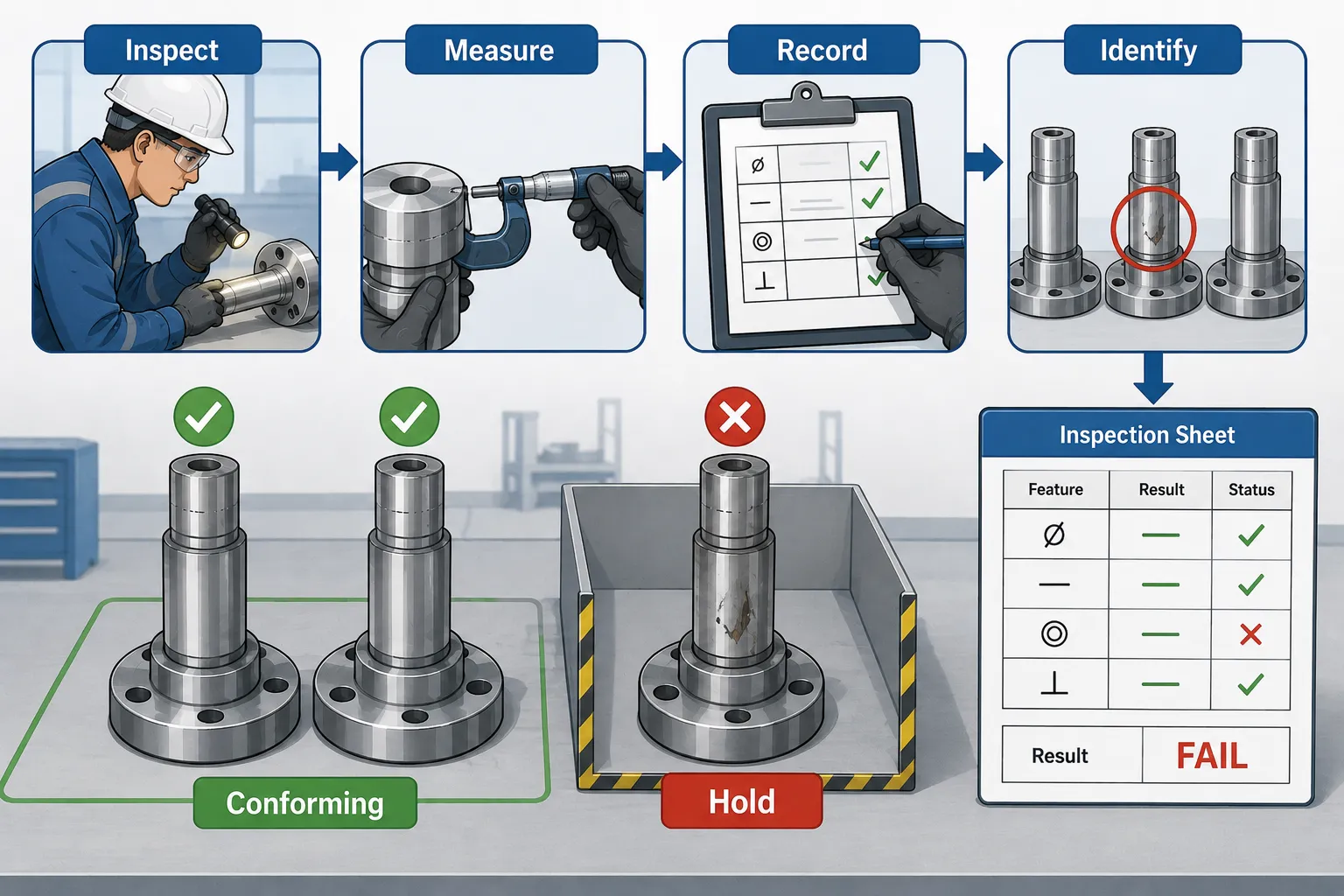
A dimensional finding should normally identify:
- Required dimension.
- Tolerance.
- Actual measurement.
- Measurement location.
- Instrument used.
- Calibration status.
- Inspector.
- Date.
- Conformance status.
For example:
Required: 75.00 ± 0.03 mm
Actual: 75.07 mm
Location: Bearing seat B
Status: Non-conforming
This is much stronger than simply stating:
“Diameter too large.”
Documenting Geometric Variations
Geometric variation should be described precisely.
Examples include:
- Shaft runout exceeds specified limit.
- Mounting surface exceeds flatness tolerance.
- Hole pattern displaced from datum.
- Bore axis deviates from specified position.
- Component face is not perpendicular to datum.
- Parallelism requirement exceeded.
The record should identify the reference used for the measurement.
Measurement Location
Measurement location is essential because the same component may have different results at different points.
For a shaft, record:
- Axial position.
- Circumferential position.
- Bearing location.
- Coupling location.
For a plate:
- Measurement grid.
- Datum reference.
- Feature location.
This improves repeatability.
Recording Actual Values
Inspectors should record actual values rather than simply marking a component as “pass” or “fail”.
Actual measurements support:
- Engineering analysis.
- Trend analysis.
- Root cause investigation.
- Corrective action.
- Supplier performance evaluation.
For example:
| Feature | Requirement | Actual | Result |
|---|---|---|---|
| Shaft diameter | 50.00 ± 0.02 mm | 50.01 mm | Pass |
| Bore diameter | 80.00 ± 0.03 mm | 80.06 mm | Fail |
| Runout | ≤ 0.03 mm | 0.07 mm | Fail |
| Length | 250 ± 0.10 mm | 250.04 mm | Pass |
This provides objective evidence.
Measurement Instrument Identification
The inspection record should identify the instrument used.
Possible information includes:
- Instrument type.
- Instrument ID.
- Serial number.
- Calibration status.
- Measurement range.
This allows the result to be traced to the equipment used.
Calibration Status
If a measurement determines component acceptance, the instrument must be suitable and appropriately calibrated.
The record should confirm:
- Calibration certificate reference.
- Calibration validity.
- Instrument identification.
An unreliable instrument can produce an unreliable acceptance decision.
Measurement Repeatability
Where a finding is significant, repeated measurements may be appropriate.
Repeat measurements can determine whether the result is:
- Consistent.
- Localised.
- Operator-dependent.
- Influenced by surface condition.
- Potentially affected by instrument positioning.
Significant measurement variation should be investigated.
Documenting Surface Defects
Surface findings should describe:
- Defect type.
- Location.
- Approximate size.
- Orientation.
- Depth where measurable.
- Component function affected.
- Applicable acceptance criterion.
Avoid subjective terms such as:
“Very damaged.”
Use objective descriptions such as:
“Longitudinal scoring observed over the bearing-contact surface.”
Documenting Cracks
Where cracks are identified, records should include:
- Location.
- Orientation.
- Approximate dimensions.
- Component identification.
- Inspection method.
- Relevant acceptance criteria.
Where necessary, additional examination should be initiated according to the applicable inspection procedure.
Documenting Corrosion
Corrosion documentation should identify:
- Location.
- Type or appearance.
- Extent.
- Measured thickness where applicable.
- Previous measurements.
- Relevant acceptance limit.
This supports deterioration trending.
Documenting Wear
Wear should be documented through actual measurements wherever possible.
Examples include:
- Reduced shaft diameter.
- Increased bore diameter.
- Gear-tooth loss.
- Increased clearance.
- Reduced thickness.
The current measurement should be compared with:
- Original design.
- Previous inspection.
- Allowable wear limit.
Documenting Runout
A runout record should identify:
- Component.
- Datum/reference axis.
- Measurement location.
- Maximum measured variation.
- Permitted limit.
- Instrument.
- Result.
Example:
Specified runout: ≤0.03 mm
Measured runout: 0.06 mm
Status: Non-conforming
Documenting Flatness
Flatness documentation should specify:
- Surface inspected.
- Reference method.
- Measurement locations.
- Maximum deviation.
- Permitted limit.
Flatness can be particularly important for:
- Flanges.
- Mounting plates.
- Machine bases.
- Sealing surfaces.
Documenting Hole Position
Hole-position deviations should be recorded relative to the specified datum.
The record may include:
- Hole identification.
- Nominal coordinates.
- Actual coordinates.
- Positional deviation.
- Permitted tolerance.
- Measurement method.
A hole may have the correct diameter but still fail its positional requirement.
Documenting Alignment Variations
Alignment findings should identify:
- Components compared.
- Reference axis.
- Measurement method.
- Angular deviation.
- Parallel deviation.
- Acceptance criterion.
Poor documentation can make subsequent alignment correction difficult.
Using Photographic Evidence
Photographs can supplement written findings.
Useful photographs should:
- Show the relevant component.
- Identify the defect location.
- Provide context.
- Be traceable to the inspection record.
- Avoid misleading angles.
Photographs should supplement, not replace, actual measurements and technical descriptions.
Inspection Sketches
Where photographs are insufficient, sketches can identify:
- Defect location.
- Measurement points.
- Datum locations.
- Component orientation.
- Feature relationships.
Simple sketches can improve understanding of complex deviations.
Inspection Mapping
For complex components, inspection mapping can divide the component into controlled zones.
For example:
- Zone A: Mounting surface.
- Zone B: Bearing seat.
- Zone C: Shaft section.
- Zone D: Coupling interface.
Findings can then be associated with specific zones.
Defect Location Coding
A controlled location code can support trend analysis.
For example:
Shaft-01 / Bearing Seat / Position 3
This is more useful than:
“Defect near bearing.”
Establishing Conformance
After recording a measurement, compare it against the approved requirement.
The decision should be:
- Conforming.
- Non-conforming.
- Requires engineering evaluation.
The inspector should not change acceptance criteria to accommodate production results.
Handling Borderline Results
Measurements close to acceptance limits should be reviewed carefully.
Consider:
- Instrument accuracy.
- Measurement repeatability.
- Applicable tolerance.
- Surface condition.
- Measurement method.
Where uncertainty affects the decision, appropriate technical evaluation should be obtained.
Non-Conformance Reporting
An NCR should clearly identify:
- Component.
- Requirement.
- Actual condition.
- Evidence.
- Applicable document.
- Deviation.
- Immediate containment.
- Required disposition.
The purpose is to control the non-conforming condition and support corrective action.
Immediate Containment
Where a component fails a critical requirement, immediate containment may involve:
- Physical segregation.
- Production hold.
- Installation hold.
- Identification tagging.
- Additional inspection.
- Notification of responsible personnel.
Containment prevents unintended use while the technical decision is made.
Engineering Disposition
Depending on the situation, a non-conforming component may require:
- Rework.
- Repair.
- Replacement.
- Engineering concession where formally permitted.
- Additional testing.
- Rejection.
The decision should be controlled and documented.
Rework Verification
After rework, the component should be re-inspected against the applicable requirements.
The new record should identify:
- Original defect.
- Rework performed.
- New measurements.
- Final acceptance status.
Trend Analysis of Geometric Variations
Repeated measurement results can reveal production trends.
For example, if shaft diameters from successive production batches show:
- 49.99 mm.
- 50.00 mm.
- 50.01 mm.
- 50.02 mm.
- 50.03 mm.
The trend may indicate process drift even before a component clearly exceeds the tolerance.
This information can support proactive process control.
Identifying Systemic Production Problems
Repeated similar findings may indicate:
- Machine-tool wear.
- Incorrect setup.
- Poor fixture condition.
- Incorrect measurement technique.
- Material movement.
- Welding distortion.
- Inadequate process control.
- Operator training gaps.
Inspection documentation therefore contributes to manufacturing improvement.
Statistical Analysis of Inspection Results
Where sufficient data are available, QA/QC teams can analyse:
- Mean measurements.
- Range.
- Standard deviation.
- Process variation.
- Trend.
- Defect frequency.
- Rejection rate.
This allows inspection data to support process improvement rather than simply identifying individual failures.
Practical Example: Shaft Production
A manufacturer produces 100 shafts with a specified diameter of:
50.00 ± 0.02 mm
Inspection results show that several components are close to the upper limit.
The QA/QC team records each actual measurement.
Analysis identifies a gradual increase in diameter over the production run.
This may indicate:
- Tool wear.
- Machine calibration drift.
- Process temperature effects.
The inspection information therefore triggers investigation before widespread non-conformance occurs.
Practical Example: Mounting Plates
A batch of mounting plates has specified hole positions.
Inspection identifies several holes outside positional tolerance.
The QA/QC team maps the affected holes and discovers that the same fixture position is associated with most deviations.
This indicates a potential fixture-related production problem.
Practical Example: Welded Fabrication
A fabricated support structure shows dimensional distortion after welding.
Inspection records identify:
- Overall dimensional deviation.
- Location of distortion.
- Weld sequence.
- Measurement points.
The findings can then support investigation into:
- Welding sequence.
- Heat input.
- Restraint.
- Fabrication technique.
Practical Example: Flange Manufacturing
A flange batch shows variation in face flatness.
Inspection records identify:
- Flange number.
- Measurement points.
- Maximum deviation.
- Applicable tolerance.
Trend analysis shows that later components have increasing deviation.
This may indicate machining-tool or setup deterioration.
Practical Example: Precision Housing
A precision housing contains several internal bores.
Inspection identifies that individual bore diameters are acceptable, but the alignment between two bores is outside the specified geometric requirement.
This demonstrates why geometric inspection must be documented alongside basic dimensional inspection.
Documentation Workflow
A structured workflow can be:
Identify Component → Confirm Requirement → Inspect → Measure → Record → Compare → Classify → Isolate → Report → Disposition → Re-Inspect
This workflow reduces the risk of defective components being released.
Inspection Record Structure
A professional record can contain:
Identification
- Component number.
- Drawing number.
- Revision.
- Batch.
- Location.
Requirement
- Dimension.
- Tolerance.
- Geometric control.
- Material.
- Acceptance criterion.
Inspection
- Method.
- Instrument.
- Calibration.
- Measurement location.
Result
- Actual value.
- Deviation.
- Conformance status.
Action
- NCR.
- Containment.
- Rework.
- Further investigation.
- Acceptance.
Benefits of Detailed Inspection Documentation
Quality Benefits
- Better conformity control.
- Improved defect detection.
- Stronger traceability.
- Reduced release of defective parts.
Engineering Benefits
- Better technical decisions.
- Stronger failure analysis.
- Improved trend identification.
- More reliable engineering evidence.
Production Benefits
- Early identification of process drift.
- Reduced rework.
- Improved process stability.
- Better production feedback.
Operational Benefits
- Reduced assembly problems.
- Improved equipment reliability.
- Lower unexpected failure risk.
- Better mechanical integrity.
Management Benefits
- Better quality performance visibility.
- Stronger supplier management.
- More effective corrective actions.
- Better resource allocation.
Common Documentation Errors
Inspectors should avoid:
- Recording only pass/fail results.
- Omitting actual measurements.
- Failing to identify measurement locations.
- Using incorrect drawing revisions.
- Omitting instrument identification.
- Failing to record calibration status.
- Using vague defect descriptions.
- Failing to isolate defective components.
- Mixing results from different components.
- Altering acceptance criteria.
- Failing to document re-inspection.
Professional Documentation Principles
Effective records should be:
- Accurate.
- Objective.
- Complete.
- Traceable.
- Legible.
- Timely.
- Consistent.
- Controlled.
- Evidence-based.
Case Study: Isolating Non-Conforming Pump Shafts
Background
A mechanical manufacturing facility produces shafts for industrial pumps. The specified shaft diameter is:
60.00 ± 0.02 mm
A batch of 50 shafts is produced.
Inspection
The QA/QC team measures the shafts at multiple locations.
Most components conform, but several show excessive variation.
Three shafts produce measurements above the maximum permitted value.
Documentation
The inspector records:
- Shaft identification.
- Drawing number.
- Revision.
- Required diameter.
- Actual measurement.
- Measurement location.
- Instrument identification.
- Calibration status.
- Inspection date.
Isolation
The three non-conforming shafts are physically identified and moved to a controlled hold area.
Investigation
The production team reviews the manufacturing process.
The analysis indicates that machine-tool wear developed during the later production stages.
Corrective Action
The organisation:
- Replaces or corrects the worn tooling.
- Verifies machine settings.
- Re-inspects affected components.
- Reviews earlier production measurements.
- Updates process monitoring.
Outcome
The documentation prevents non-conforming shafts from entering assembly and also identifies a production-system issue.
Lessons Learned
The case demonstrates that detailed inspection records can achieve two objectives simultaneously:
- Control individual defective components.
- Identify wider manufacturing problems.
Integrating Inspection Findings With QA/QC Management
Inspection records should feed into:
- NCR systems.
- Corrective actions.
- Preventive actions.
- Supplier evaluations.
- Production reviews.
- Process improvement.
- Management reporting.
This transforms inspection from a purely reactive activity into a source of continuous improvement.
Integrating Findings With Supplier Quality
Where components are externally manufactured, inspection data can support supplier performance evaluation.
Useful indicators include:
- Rejection rate.
- Dimensional defect frequency.
- Repeat defects.
- NCR frequency.
- Rework rate.
- Corrective-action effectiveness.
Digital Inspection Records
Digital inspection systems can improve:
- Data retrieval.
- Traceability.
- Trend analysis.
- Record control.
- Reporting speed.
- Component status visibility.
However, digital records still require controlled procedures and accurate data entry.
Inspection Data and Production Decisions
Quality data can support decisions such as:
- Whether to continue production.
- Whether to stop a process.
- Whether additional inspection is needed.
- Whether a supplier requires corrective action.
- Whether tooling should be replaced.
- Whether process parameters require review.
Key Takeaways
Effective inspection documentation should:
- Identify the exact component.
- Reference the correct design requirement.
- Record actual measurements.
- Identify geometric variations.
- Record measurement locations.
- Identify inspection instruments.
- Confirm calibration status.
- Compare results with acceptance criteria.
- Classify findings objectively.
- Physically isolate non-conforming components.
- Initiate NCR processes where required.
- Maintain traceability.
- Support engineering disposition.
- Verify rework.
- Analyse recurring trends.
- Feed findings into continuous improvement.
Conclusion
Detailed documentation of inspection findings and geometric variations is essential for maintaining effective mechanical QA/QC because it converts physical inspection results into reliable engineering evidence. A well-controlled record establishes the relationship between the manufactured component, its design requirement, the inspection method, the actual measurement, and the final conformity decision. This enables quality teams to identify components that fail baseline production targets and prevent those components from progressing into assembly, installation, commissioning, or operational service.
The process becomes particularly valuable when dimensional and geometric results are recorded systematically. Shaft diameter, runout, flatness, hole position, alignment, clearance, surface condition, and other characteristics should be documented using actual values, defined measurement locations, appropriate instruments, and applicable tolerances. Where deviations occur, physical segregation, NCR management, engineering disposition, rework, and re-inspection provide controlled mechanisms for managing the affected components. This approach protects product quality while maintaining traceability throughout the manufacturing process.
Detailed inspection records also provide information that extends beyond individual component acceptance. When similar deviations appear repeatedly, QA/QC teams can identify production trends, process drift, equipment wear, fixture problems, tooling deterioration, or other systemic causes. Inspection data can therefore support corrective action, process optimisation, supplier evaluation, and continuous improvement. By integrating accurate inspection documentation with the wider QA/QC management system, mechanical engineering organisations can reduce defective-product release, minimise rework, strengthen production control, improve mechanical reliability, and maintain consistent standards of manufacturing quality and mechanical integrity.