
Lesson 8: Recommend corrective and preventive measures based on inspection outcomes.
Effective inspection is only valuable when its findings lead to appropriate action. Lesson 8: Recommend corrective and preventive measures based on inspection outcomes focuses on how electrical QA/QC professionals interpret inspection results and translate identified deficiencies, non-conformities, recurring issues, and performance concerns into practical corrective and preventive measures. In complex electrical projects, inspection outcomes may relate to installation quality, equipment condition, testing performance, workmanship, documentation, material conformity, electrical connections, protection systems, or compliance with approved requirements. A competent QA/QC professional must therefore move beyond simply identifying a problem and recommend actions that address the immediate condition while also reducing the likelihood of recurrence.
Corrective measures are concerned with addressing identified non-conformities and restoring conformity with specified requirements, while preventive measures focus on reducing the possibility of similar problems occurring in the future. This requires professional judgement, evidence-based analysis, root cause consideration, risk evaluation, and an understanding of applicable electrical QA/QC procedures. Learners will explore how inspection outcomes can be reviewed systematically, how corrective actions can be prioritised according to technical significance and risk, and how preventive controls can be incorporated into inspection, testing, installation, supervision, documentation, training, and quality management processes. The lesson also considers the importance of verification, re-inspection, re-testing, effectiveness reviews, and maintaining clear quality records.
From an international electrical QA/QC perspective, recommending corrective and preventive measures supports continual improvement, audit readiness, reliable project delivery, and long-term asset integrity. Learners will develop the ability to connect inspection evidence with practical improvement actions, communicate recommendations clearly, and assess whether implemented measures have effectively resolved the original issue. Through workplace-oriented examples and realistic quality scenarios, this lesson develops professional decision-making skills required by Electrical QA/QC Engineers, inspectors, supervisors, contractors, commissioning teams, and quality professionals working across construction, industrial, commercial, infrastructure, manufacturing, maintenance, and engineering environments.
1: Critically Interpret Inspection Outcomes to Differentiate Between Isolated Defects and Systemic Electrical Issues
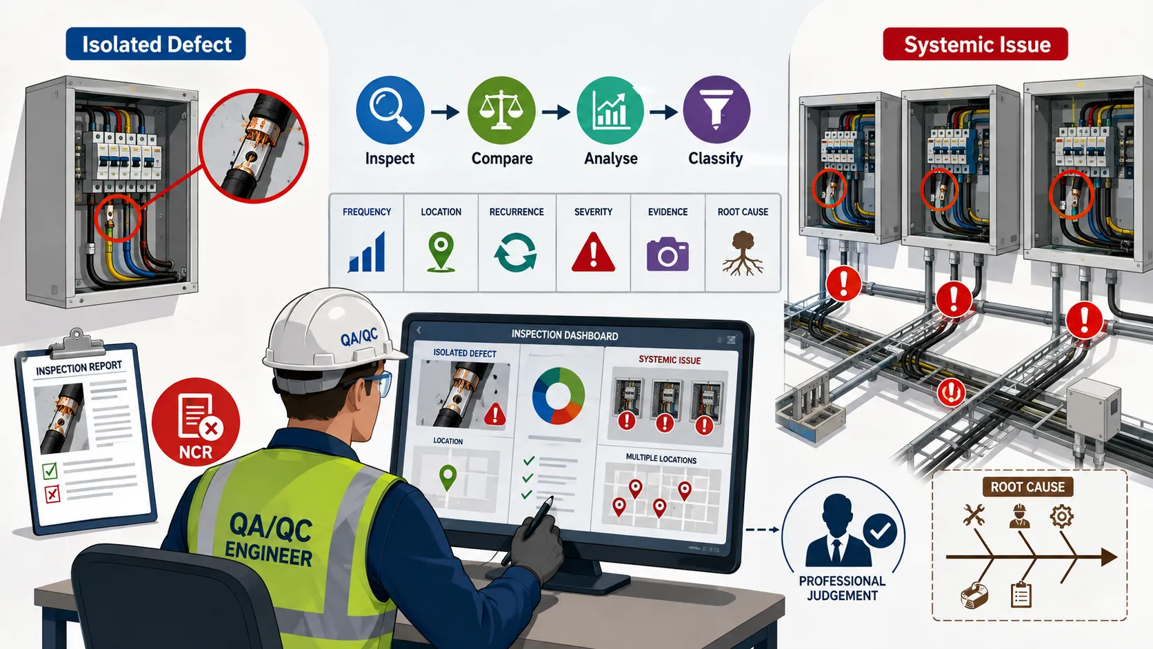
Electrical inspection is not simply a process of identifying whether an installation, component, or system appears acceptable at a particular point in time. At Level 6 professional practice, the Electrical QA/QC Engineer is expected to interpret inspection outcomes critically and determine what the findings mean for the wider quality performance of the project or asset. A single defect may represent an isolated workmanship error, a localised installation problem, or an unusual event. However, the same type of defect occurring repeatedly across different locations, equipment items, work teams, suppliers, or project stages may indicate a systemic electrical issue requiring a broader corrective response.
The ability to distinguish between an isolated defect and a systemic issue is therefore an important professional judgement skill. It requires the engineer to examine inspection evidence, compare findings, identify patterns, consider frequency and severity, evaluate contributing factors, review relevant documentation, and determine whether the problem is confined to one location or reflects a weakness within a process or control system. This distinction directly influences the appropriate corrective and preventive action. Treating a systemic problem as an isolated defect can allow similar failures to continue, while treating every isolated defect as a systemic failure can create unnecessary disruption, cost, investigation, and corrective work.
Critical interpretation requires more than counting defects. The QA/QC professional must understand the context in which the findings occurred and consider interacting factors such as design requirements, material selection, installation practices, supervision, competence, inspection methods, supplier performance, environmental conditions, work sequencing, documentation, testing, and change control. The purpose is to establish whether the evidence supports a local correction or whether a wider investigation is justified.
Understanding Inspection Outcomes
An inspection outcome is the result obtained after an inspection, examination, measurement, test, or verification activity has been completed and evaluated against defined requirements.
Inspection outcomes may include:
- Conforming installation.
- Minor defect.
- Major defect.
- Non-conformance.
- Observation.
- NDE indication requiring evaluation.
- Test failure.
- Incomplete inspection.
- Documentation deficiency.
- Repeated defect.
- Potential systemic issue.
- Condition requiring engineering review.
An inspection outcome should not be interpreted in isolation when the objective is to understand wider quality performance. The engineer should consider the relationship between the individual finding and other available evidence.
For example, one incorrectly labelled cable may represent an isolated installation error. However, if the same labelling problem is identified on multiple floors and across several cable routes, the issue may indicate a systemic weakness in the cable identification process, supervision, approved drawings, installation procedures, or workforce understanding.
Isolated Defect
An isolated defect is a non-conforming condition that appears to be limited to a specific item, location, activity, or event and does not, based on available evidence, indicate a wider failure of the process.
Typical characteristics include:
- Limited occurrence.
- Clearly defined location.
- No similar findings in sampled areas.
- Specific identifiable cause.
- Effective local correction available.
- No evidence of widespread process failure.
- Other comparable installations demonstrate conformity.
An isolated defect still requires appropriate correction and documentation. The term “isolated” does not mean unimportant. A single defect involving a critical electrical system may require immediate action because of its potential consequences.
Systemic Electrical Issue
A systemic electrical issue is a recurring, widespread, process-related, or organisational problem that affects multiple items, locations, activities, or stages of an electrical project or asset lifecycle.
It may indicate weakness in:
- Design control.
- Procurement.
- Material control.
- Installation procedures.
- Workforce competence.
- Supervision.
- Inspection planning.
- Testing.
- Document control.
- Change management.
- Contractor management.
- Quality procedures.
- Training.
- Communication.
- Corrective action processes.
A systemic issue requires more than repairing individual defects. The underlying process or control contributing to recurrence should be examined.
Difference Between Isolated and Systemic Issues
The distinction between isolated and systemic issues is not always immediately obvious. A professional engineer should avoid making a conclusion based solely on the first defect identified.
| Aspect | Isolated Defect | Systemic Electrical Issue |
|---|---|---|
| Occurrence | Usually limited to one or few locations | Repeated across multiple locations or activities |
| Pattern | Localised | Recurring or widespread |
| Cause | Often specific and identifiable | Often linked to process or control weakness |
| Scope | Individual item or activity | Multiple items, teams or processes |
| Corrective action | Local correction may be sufficient | Wider corrective and preventive action required |
| Investigation | Focused investigation | Broader root-cause investigation |
| Verification | Re-inspect affected item | Sample wider population or process |
| Risk | May be limited or significant | Potentially widespread or cumulative |
| Documentation | Individual NCR or finding | Trend, repeated NCRs or systemic review |
| Prevention | Local improvement | Process, training, procedure or control improvement |
The table should not be treated as an automatic classification tool. Professional judgement remains essential because a single finding can sometimes reveal a serious systemic weakness.
Key Principles of Critical Interpretation
Evidence Before Conclusion
The first principle is to avoid making conclusions before sufficient evidence has been considered.
A QA/QC Engineer should ask:
- What exactly was found?
- Where was it found?
- When was it found?
- How was it detected?
- Which requirement was not met?
- How serious is the condition?
- Has the same condition been found elsewhere?
- What comparable work has already been inspected?
- What process produced the condition?
- Is there evidence of recurrence?
The engineer should distinguish between what is known, what is suspected, and what requires further investigation.
Frequency Matters
Repeated findings can provide evidence of a systemic problem.
For example:
- One incorrectly installed cable gland may be isolated.
- Five similar gland defects in one area require further investigation.
- Similar defects across several buildings strongly suggest a wider process issue.
However, frequency alone does not determine classification. A single high-risk defect can require systemic review if its potential cause could affect other installations.
Severity Matters
The severity of an inspection outcome should influence the depth of investigation.
Consider:
- Electrical safety implications.
- Equipment reliability.
- Functional performance.
- Fire risk implications.
- Protection performance.
- Asset integrity.
- Operational consequences.
- Compliance implications.
- Potential extent of affected work.
A low-frequency issue with severe potential consequences may deserve more attention than numerous minor documentation errors.
Recurrence Matters
Recurrence is one of the strongest indicators that an issue may be systemic.
Recurrence may occur:
- At different locations.
- On different equipment.
- Across different work shifts.
- Among different subcontractors.
- During different project stages.
- Across multiple inspection dates.
Repeated findings should trigger trend analysis rather than simply repeated closure of individual NCRs.
Sources of Evidence for Differentiating Issues
A competent QA/QC Engineer should use multiple evidence sources where appropriate.
Inspection Records
Inspection records can reveal:
- Defect frequency.
- Defect location.
- Defect type.
- Work package involved.
- Inspection stage.
- Inspector observations.
Test Results
Testing may reveal recurring performance problems.
Examples include:
- Repeated insulation resistance failures.
- Recurring continuity problems.
- Repeated protection testing discrepancies.
- Similar equipment performance abnormalities.
NCR Records
NCR data can provide valuable trend information.
The engineer can review:
- Number of NCRs.
- NCR categories.
- Locations.
- Responsible organisations.
- Recurring causes.
- Closure time.
- Repeated NCRs.
NDE Findings
Where applicable, NDE records may identify recurring indications or conditions.
The engineer should examine:
- Indication type.
- Location.
- Frequency.
- Distribution.
- Examination method.
- Evaluation outcome.
Installation Records
Installation inspection data can reveal recurring workmanship problems such as:
- Incorrect cable routing.
- Poor termination.
- Incorrect identification.
- Inadequate support.
- Incorrect equipment installation.
Design and Document Records
Some recurring physical defects may originate from documentation problems.
The engineer should review:
- Approved drawings.
- Specifications.
- Design revisions.
- Work instructions.
- Method statements.
- Inspection procedures.
- Change records.
Training and Competence Records
Repeated workmanship problems may indicate:
- Inadequate training.
- Misunderstanding of requirements.
- Lack of supervision.
- Competence gaps.
- Poor communication.
Supplier and Material Records
Recurring defects may be associated with:
- Material quality.
- Supplier performance.
- Incorrect specification.
- Unapproved substitutions.
- Storage conditions.
- Handling practices.
Process for Critically Interpreting Inspection Outcomes
Step 1: Define the Finding
Record the finding precisely.
The description should establish:
- What happened.
- Where it occurred.
- Which item was affected.
- Which requirement applied.
- What evidence supports the finding.
Avoid vague statements such as “poor electrical installation”.
Instead, identify the actual condition.
Step 2: Establish the Acceptance Requirement
Determine the requirement against which the condition was assessed.
This may be based on:
- Approved drawings.
- Project specifications.
- Inspection procedures.
- Approved installation requirements.
- Manufacturer requirements.
- Applicable project quality criteria.
The conclusion should be based on a defined requirement rather than personal preference.
Step 3: Assess Severity
Determine the significance of the finding.
Consider:
- Safety.
- Quality.
- Reliability.
- Functionality.
- Compliance.
- Cost.
- Programme.
- Asset integrity.
Step 4: Determine Initial Extent
Ask whether the finding appears limited to one item or potentially affects similar work.
Review:
- Adjacent installations.
- Same equipment type.
- Same work package.
- Same subcontractor.
- Same material batch.
- Same installation period.
Step 5: Search for Similar Findings
Review existing quality records.
Search for:
- Similar descriptions.
- Similar equipment.
- Similar locations.
- Similar NCR categories.
- Similar test failures.
- Similar installation errors.
Step 6: Analyse Patterns
Look for relationships involving:
- Time.
- Location.
- Contractor.
- Equipment type.
- Work team.
- Material.
- Procedure.
- Design revision.
Step 7: Consider Possible Causes
Potential contributing factors may include:
- Design ambiguity.
- Incorrect drawing revision.
- Inadequate procedure.
- Poor supervision.
- Competence gap.
- Material issue.
- Time pressure.
- Inadequate inspection coverage.
- Communication failure.
- Uncontrolled change.
Step 8: Classify the Issue
Based on available evidence, determine whether it appears to be:
- Isolated.
- Repeated.
- Potentially systemic.
- Systemic and confirmed.
- Requiring further investigation.
Step 9: Determine the Appropriate Response
An isolated issue may require:
- Local correction.
- Re-inspection.
- Record update.
- Targeted preventive action.
A systemic issue may require:
- Wider inspection.
- Root-cause investigation.
- Procedure review.
- Training.
- Design review.
- Supplier review.
- Process change.
- Increased inspection.
- Preventive controls.
Step 10: Verify Effectiveness
The investigation does not end when the physical defect is corrected.
Verification should determine whether:
- The original condition was corrected.
- Similar conditions remain elsewhere.
- The underlying cause was addressed.
- Preventive measures are effective.
Analysing Patterns in Inspection Findings
Pattern recognition is a valuable professional skill.
Location Pattern
If defects occur repeatedly in one location, investigate:
- Local supervision.
- Installation conditions.
- Environmental influences.
- Access restrictions.
- Specific work team.
If the same defect occurs across many locations, investigate wider process factors.
Time Pattern
If defects increase during a particular project phase or work period, consider:
- Programme pressure.
- Changes in workforce.
- Shift arrangements.
- Reduced supervision.
- Accelerated installation.
Contractor Pattern
If one subcontractor has significantly higher defect rates than comparable teams, review:
- Competence.
- Procedures.
- Supervision.
- Training.
- Quality performance.
The finding should not automatically be attributed to contractor performance without evidence.
Equipment Pattern
If the same type of equipment repeatedly fails inspection, investigate:
- Equipment specification.
- Supplier.
- Installation method.
- Manufacturer requirements.
- Storage.
- Design interface.
Material Pattern
If defects are concentrated around a particular material batch or supplier, consider:
- Material conformity.
- Storage.
- Handling.
- Supplier controls.
- Procurement specifications.
Practical Indicators of a Systemic Electrical Issue
A systemic issue may be suspected where:
- Similar defects occur repeatedly.
- Findings involve different locations.
- Multiple teams report similar problems.
- NCRs repeatedly identify the same cause.
- Corrective actions fail to prevent recurrence.
- Test failures show a consistent pattern.
- Inspection findings increase after a process change.
- Several records reference the same unclear requirement.
- Multiple installations are affected by one design issue.
- The same documentation error appears across teams.
These indicators should trigger investigation rather than automatic classification.
Practical Indicators of an Isolated Defect
An issue may reasonably be considered isolated where:
- Only one occurrence is identified.
- Similar work has been inspected successfully.
- The cause is clearly localised.
- The affected item is uniquely different.
- No related NCR trend exists.
- Wider sampling does not identify recurrence.
- Corrective action is clearly defined.
- Re-inspection confirms conformity.
Even in this situation, the engineer should retain sufficient evidence to justify the classification.
Practical Example: Incorrect Cable Identification
An electrical inspector discovers that one installed cable has an incorrect identification label.
The initial finding is:
“Cable C-27 identification does not correspond with the approved cable schedule.”
The engineer investigates.
The following evidence is found:
- One cable affected.
- Adjacent cables correctly labelled.
- Same installation team has completed several compliant areas.
- No similar NCRs exist.
- Cable schedule is clear.
- The incorrect label resulted from a local installation error.
The evidence supports an isolated defect.
The appropriate response may include:
- Replace the incorrect label.
- Verify the cable identification.
- Re-inspect the affected cable.
- Record closure.
- Brief the installer where appropriate.
A wider systemic investigation may not be justified unless additional evidence emerges.
Practical Example: Repeated Cable Termination Problems
During inspection of several distribution boards, the QA/QC team identifies multiple cable termination defects.
Findings include:
- Incorrect gland installation.
- Inadequate termination preparation.
- Poor identification.
- Repeated workmanship issues.
The defects are found:
- On several floors.
- Across multiple panels.
- Over several inspection dates.
- Among more than one installation team.
The pattern suggests that the problem is unlikely to be limited to one worker or one cable.
The QA/QC Engineer should consider:
- Reviewing the termination procedure.
- Assessing installer competence.
- Reviewing supervision.
- Expanding inspection to similar completed work.
- Reviewing training.
- Checking whether the approved detail is clear.
- Analysing related NCRs.
The response should address the wider process rather than simply repairing each individual termination.
Practical Example: Repeated Insulation Resistance Failures
A commissioning team identifies several cables with insulation resistance results below the project acceptance requirement.
Rather than treating every failed cable independently, the QA/QC Engineer reviews the results.
The analysis identifies that:
- Several cables were installed during the same period.
- The cables passed earlier visual inspection.
- Similar results occur in one installation area.
- Environmental conditions may have affected the installation.
- Cable storage and handling records require review.
The correct professional response is to investigate the pattern and determine whether the issue originates from installation, environmental exposure, material condition, testing procedure, or another contributing factor.
The evidence should guide the final classification.
Practical Example: Repeated Documentation Findings
A project experiences repeated inspection records with:
- Missing drawing revisions.
- Missing equipment identifiers.
- Incomplete acceptance criteria.
Initially, these may appear to be minor administrative defects.
However, when the same weaknesses are identified across different inspectors and subcontractors, the QA/QC Engineer should consider whether the problem is systemic.
Potential causes may include:
- Poor document-control procedure.
- Inadequate inspection forms.
- Insufficient training.
- Weak document review.
- Poor digital system design.
The corrective response should therefore address the documentation process rather than simply correcting individual records.
Distinguishing Root Cause from Symptom
A major professional challenge is distinguishing the visible defect from the underlying cause.
For example:
Symptom:
Incorrect cable termination.
Possible contributing cause:
Installer did not follow the approved termination procedure.
Potential deeper cause:
Procedure was not adequately communicated or supervised.
Potential systemic cause:
The project lacked a controlled competency and supervision process for cable termination activities.
This layered analysis helps prevent superficial corrective action.
Questions for Root-Cause Consideration
The engineer may ask:
- Why did the defect occur?
- Why was it not detected earlier?
- Was the requirement clear?
- Was the approved procedure available?
- Was the worker competent?
- Was adequate supervision provided?
- Was the correct material available?
- Was the design clear?
- Was the work performed under unusual conditions?
- Has the same problem occurred elsewhere?
The objective is not to assign blame. It is to establish why the condition occurred and whether controls need improvement.
Use of Sampling in Systemic Assessment
A QA/QC Engineer may need to expand inspection when a potentially systemic issue is identified.
Sampling can help determine:
- Whether the defect exists elsewhere.
- How widespread the issue is.
- Whether one work area is affected.
- Whether multiple teams are involved.
- Whether the issue relates to a specific material or equipment type.
The sampling approach should be proportionate to:
- Risk.
- Severity.
- Frequency.
- Project stage.
- Population affected.
- Available evidence.
A single additional inspection may not be sufficient when evidence suggests a widespread problem.
Interaction Between Risk and Systemic Issues
The distinction between isolated and systemic findings should also consider risk.
A systemic issue may be:
- Frequent but low consequence.
- Less frequent but high consequence.
- Widespread and high consequence.
Similarly, an isolated defect may be low risk or highly significant depending on the affected equipment and condition.
The engineer should therefore consider:
- Probability.
- Consequence.
- Exposure.
- Criticality.
- Extent.
- Detectability.
This supports proportionate decision-making.
Inspection Outcomes and Corrective Action Decisions
Inspection interpretation should lead to appropriate action.
For an Isolated Defect
Possible actions include:
- Correct the affected item.
- Re-inspect.
- Update the inspection record.
- Provide targeted feedback.
- Monitor subsequent work.
For a Potential Systemic Issue
Possible actions include:
- Expand inspection.
- Review similar installations.
- Analyse NCR trends.
- Review procedures.
- Conduct competency assessment.
- Review supervision.
- Examine design information.
- Review supplier performance.
- Introduce preventive controls.
The decision should be based on evidence.
Common Errors in Interpreting Inspection Outcomes
Treating Every Finding as Isolated
This is one of the most significant weaknesses in quality management.
If every NCR is closed individually without trend analysis, recurring problems may continue.
Assuming Repetition Automatically Means Systemic Failure
Repeated findings are an important indicator, but the engineer should still investigate the context and common factors.
Focusing Only on Physical Defects
A physical defect may originate from:
- Design.
- Documentation.
- Procurement.
- Training.
- Supervision.
- Process control.
Ignoring Previous Findings
Historical inspection records can provide important evidence of recurrence.
Closing Corrective Actions Without Effectiveness Review
A repaired item does not necessarily demonstrate that the underlying problem has been controlled.
Blaming Individuals Without Process Analysis
Individual errors may be symptoms of wider weaknesses in:
- Training.
- Procedures.
- Supervision.
- Communication.
- Work planning.
Case Study: Differentiating Isolated and Systemic Electrical Defects
Project Background
A large industrial facility is undergoing electrical installation and commissioning. The project includes switchgear, distribution boards, power cables, control panels, earthing systems and associated electrical infrastructure.
During routine QA/QC inspection, an incorrect cable gland is identified on one distribution board.
Initial Finding
The inspector records:
“Cable C-114 gland does not conform to the approved installation requirement.”
The QA/QC Engineer initially treats the finding as potentially isolated.
Investigation
The engineer reviews:
- Inspection records.
- Cable installation records.
- NCR history.
- Approved drawings.
- Installation procedures.
- Installer information.
- Similar completed work.
The review identifies three additional gland defects in other areas.
Further analysis shows that:
- The same installation procedure was used.
- Similar errors occurred across different panels.
- Multiple installers were involved.
- The issue was not limited to one person.
- The approved procedure contained insufficient visual guidance.
Interpretation
The evidence now indicates a potential systemic issue.
The common factor is not simply individual workmanship. The problem appears related to the installation control process and clarity of the approved procedure.
Corrective and Preventive Response
The QA/QC team recommends:
- Correcting identified gland installations.
- Expanding inspection to comparable installations.
- Reviewing the termination procedure.
- Improving installation guidance.
- Providing targeted workforce training.
- Increasing inspection coverage temporarily.
- Re-inspecting affected work.
- Monitoring subsequent inspection results.
Verification
After implementation, further inspections show that similar defects have significantly reduced.
This provides evidence that the corrective and preventive measures are addressing the wider issue.
Case Study Conclusion
The case demonstrates why critical interpretation is essential. The first defect appeared isolated, but systematic review of related evidence revealed a wider process weakness. A purely local correction would have left similar defects undiscovered.
Key Benefits of Differentiating Isolated and Systemic Issues
Better Corrective Action
The organisation can select an appropriate response based on the actual extent of the problem.
Reduced Recurrence
Systemic analysis helps address underlying causes rather than repeatedly correcting symptoms.
Improved Quality Performance
Trend analysis provides information that can improve:
- Procedures.
- Training.
- Supervision.
- Inspection planning.
- Design coordination.
Better Resource Allocation
Resources can be directed towards areas presenting the greatest quality concern.
Improved Risk Management
Understanding whether a problem is local or widespread improves the accuracy of risk decisions.
Stronger Audit Evidence
Auditors can see that the organisation:
- Analyses findings.
- Identifies trends.
- Investigates recurrence.
- Implements proportionate actions.
- Verifies effectiveness.
Improved Client Confidence
Clients are more likely to have confidence in a QA/QC system that demonstrates learning from inspection findings rather than simply closing individual records.
Improved Continual Improvement
Systemic analysis turns inspection data into organisational learning.
Responsibilities of the Electrical QA/QC Engineer
The Electrical QA/QC Engineer should demonstrate professional judgement when interpreting inspection outcomes.
Key responsibilities may include:
- Reviewing inspection findings.
- Assessing severity.
- Identifying recurrence.
- Analysing trends.
- Reviewing NCR history.
- Comparing similar installations.
- Evaluating potential causes.
- Determining whether wider inspection is required.
- Coordinating technical investigations.
- Recommending corrective actions.
- Recommending preventive measures.
- Monitoring recurrence.
- Verifying effectiveness.
- Reporting systemic trends to management.
The engineer should maintain an evidence-based approach and avoid premature conclusions.
Recommended Inspection Outcome Review Checklist
Before classifying a finding, the QA/QC Engineer should consider:
- What exactly was found?
- Which requirement applies?
- What equipment is affected?
- Where is the issue located?
- How severe is the condition?
- Has the same problem occurred elsewhere?
- Are similar records available?
- Is there a recurring trend?
- Is there a common contractor or process?
- Is the design clear?
- Is the procedure adequate?
- Are personnel competent?
- Was appropriate supervision provided?
- Could materials contribute to the problem?
- Could environmental conditions influence the finding?
- Does the issue affect similar completed work?
- Is wider inspection necessary?
- What evidence supports the classification?
- How will effectiveness be verified?
Conclusion
Critically interpreting inspection outcomes is a fundamental Level 6 electrical QA/QC competency because the significance of a finding cannot always be understood from the individual defect alone. A professional Electrical QA/QC Engineer must determine whether an inspection outcome represents a localised and isolated condition or whether it indicates a wider weakness within design, procurement, installation, testing, supervision, competence, documentation, change control, or another quality process.
The distinction should be based on objective evidence, not assumptions. Frequency, severity, recurrence, location, affected equipment, responsible processes, historical NCRs, inspection trends, test results, and comparable installations should all be considered when appropriate. A single defect may sometimes remain isolated, while a small number of similar findings can reveal a systemic issue. Conversely, repeated findings do not automatically prove a systemic failure; the engineer must investigate the common factors and establish whether a wider relationship exists.
Where an issue is genuinely isolated, a focused correction and verification may be appropriate. Where evidence indicates a systemic problem, the response should extend beyond repairing individual defects. Wider inspection, root-cause analysis, procedure review, competency assessment, improved supervision, design review, supplier evaluation, preventive controls, and effectiveness monitoring may be necessary.
The ultimate purpose of critical inspection interpretation is not simply to classify defects. It is to transform inspection information into informed quality decisions. By recognising patterns, investigating causes, evaluating risk, and distinguishing local conditions from wider process weaknesses, electrical QA/QC professionals can recommend more effective corrective and preventive measures. This strengthens quality assurance, reduces recurrence, improves project performance, supports audit readiness, protects electrical system integrity, and contributes to continual improvement throughout the project and asset lifecycle.
2: Formulate Advanced Corrective Actions to Resolve Immediate Quality Failures in Electrical Components
Formulating advanced corrective actions is a critical responsibility within electrical Quality Assurance and Quality Control (QA/QC), particularly when inspection, testing, commissioning, or NDE activities identify failures in electrical components. At Level 6 professional practice, corrective action should not be limited to repairing the visible defect. The Electrical QA/QC Engineer must interpret the inspection evidence, establish the immediate condition, assess its significance, determine the appropriate technical response, control affected work, and formulate an action that restores conformity while protecting safety, reliability, functionality, and project requirements.
An effective corrective action provides a controlled response to an identified quality failure. It should clearly define what must be corrected, which component or installation is affected, who is responsible, what technical requirements apply, what evidence is required, and how the completed action will be verified. In complex electrical projects, corrective action may involve component replacement, re-termination, reinstallation, adjustment, repair, re-testing, additional inspection, controlled engineering review, or other technically justified measures. The action should be proportionate to the nature and significance of the failure and should be based on objective inspection and testing evidence.
Advanced corrective action also requires consideration of the wider quality environment. A failed electrical component may be affected by incorrect installation, unsuitable material, manufacturing defects, damage during transportation, storage conditions, incorrect drawings, workmanship, inadequate testing, environmental exposure, or uncontrolled changes. Therefore, the QA/QC Engineer should distinguish between simply restoring the component and establishing whether additional controls are necessary to prevent the same failure from affecting related equipment. Corrective actions should be documented, implemented, monitored, verified, and formally closed using controlled QA/QC processes.
Meaning of Advanced Corrective Action
An advanced corrective action is a structured, evidence-based response designed to address an identified electrical quality failure, restore the affected component or installation to the required condition, and provide objective evidence that the failure has been effectively resolved.
Corrective action may involve:
- Identifying the failed component.
- Controlling the affected equipment.
- Evaluating the failure.
- Determining the applicable requirement.
- Establishing the correction method.
- Obtaining technical approval where required.
- Implementing the correction.
- Re-inspecting the affected component.
- Re-testing where appropriate.
- Recording objective evidence.
- Confirming conformity.
- Closing the relevant quality record.
The term “advanced” reflects the level of professional judgement involved. The objective is not simply to tell a contractor to “repair the defect”. The action should define an appropriate and verifiable route from failure identification to confirmed conformity.
Purpose of Corrective Actions in Electrical QA/QC
Corrective actions serve several important purposes within an electrical quality management process.
They help to:
- Restore conformity.
- Control defective or non-conforming components.
- Prevent defective work from progressing.
- Protect electrical system performance.
- Provide documented evidence of resolution.
- Support commissioning.
- Reduce repeated inspection failures.
- Protect project quality objectives.
- Support contractual compliance.
- Improve confidence in completed work.
A corrective action should therefore be considered part of the overall quality-control cycle:
Inspection → Finding → Evaluation → Corrective Action → Verification → Closure
Where necessary, this can be extended to:
Inspection → Finding → Immediate Correction → Root-Cause Review → Preventive Action → Verification → Continual Improvement
Key Concepts in Formulating Corrective Actions
Immediate Correction
Immediate correction addresses the physical or technical condition identified during inspection.
Examples include:
- Replacing a damaged component.
- Re-terminating a cable.
- Correcting incorrect identification.
- Reinstalling incorrectly mounted equipment.
- Repairing an approved component where permitted.
- Replacing damaged insulation.
- Correcting an unsuitable connection.
Immediate correction restores the affected item but does not necessarily address why the failure occurred.
Corrective Action
Corrective action is the controlled response designed to address an identified non-conformity and restore conformity.
It should identify:
- The failure.
- The affected item.
- The required action.
- The responsible party.
- The applicable requirement.
- The verification method.
- The evidence required for closure.
Verification
Verification establishes whether the correction has actually achieved the required result.
Verification may include:
- Visual inspection.
- Dimensional checks.
- Electrical testing.
- Functional testing.
- NDE.
- Document review.
- Re-inspection.
- Commissioning checks.
Effectiveness
Effectiveness concerns whether the implemented action has adequately resolved the identified condition and, where appropriate, reduced the likelihood of recurrence.
Corrective Action Versus Preventive Action
Although closely related, corrective and preventive actions have different purposes.
| Aspect | Corrective Action | Preventive Action |
|---|---|---|
| Primary purpose | Resolve an identified failure | Reduce likelihood of future failure |
| Trigger | Existing non-conformity or failure | Identified potential weakness or risk |
| Focus | Current problem | Future recurrence or potential problem |
| Example | Replace damaged cable termination | Improve termination training |
| Evidence | Re-inspection and testing | Monitoring and trend review |
| Scope | Affected item or wider affected population | Relevant process or population |
| Outcome | Restored conformity | Improved control |
| QA/QC role | Verify correction | Monitor preventive effectiveness |
A mature QA/QC system often uses the immediate corrective action as the starting point for identifying whether preventive measures are also necessary.
Sources of Information for Corrective Action Formulation
Corrective actions should be based on reliable evidence.
Relevant sources may include:
- Inspection reports.
- Test certificates.
- NDE reports.
- NCRs.
- Approved drawings.
- Technical specifications.
- Manufacturer information.
- Installation procedures.
- Inspection and Test Plans.
- Material approval records.
- Equipment schedules.
- Photographic evidence.
- Commissioning records.
- Previous quality findings.
The more significant the failure, the greater the need for a well-supported technical decision.
Process for Formulating Advanced Corrective Actions
Step 1: Identify the Immediate Quality Failure
The first step is to establish exactly what has failed.
The finding should identify:
- Component.
- Equipment number.
- Location.
- Failure condition.
- Date.
- Inspection activity.
- Applicable requirement.
For example:
“Distribution Board DB-04 contains a cable termination with inadequate mechanical securing and does not conform to the approved installation requirement.”
This is more useful than:
“DB-04 has poor workmanship.”
Step 2: Control the Non-Conforming Condition
The affected item should be appropriately controlled until a technical decision is made.
Depending on the situation, this may involve:
- Stopping further work.
- Segregating defective materials.
- Preventing energisation.
- Identifying affected equipment.
- Applying hold points.
- Raising an NCR.
- Informing responsible personnel.
- Protecting the component from further damage.
The control should be proportionate to the risk and project requirements.
Step 3: Assess the Significance
The QA/QC Engineer should determine the significance of the failure.
Consider:
- Electrical safety.
- Functional performance.
- Equipment reliability.
- System criticality.
- Potential damage.
- Compliance.
- Programme impact.
- Cost implications.
- Potential extent.
A failure in a non-critical auxiliary component may require a different response from a failure affecting a critical distribution system.
Step 4: Establish the Requirement
The corrective action must be linked to an applicable requirement.
Potential references include:
- Approved drawings.
- Project specifications.
- Inspection criteria.
- Approved procedures.
- Manufacturer requirements.
- Project quality plan.
- Applicable technical requirements.
The requirement should be clear enough to support verification.
Step 5: Determine the Correction Method
The engineer should identify the most appropriate technical solution.
Potential solutions include:
- Adjustment.
- Reinstallation.
- Repair.
- Replacement.
- Re-termination.
- Re-testing.
- Additional inspection.
- Controlled engineering review.
The chosen method should be technically appropriate and consistent with approved project requirements.
Step 6: Evaluate Affected Population
Where the failure could affect similar components, determine whether additional inspections are required.
Review:
- Similar equipment.
- Same installation team.
- Same material batch.
- Same supplier.
- Same work package.
- Same drawing.
- Same installation procedure.
This prevents a correction from being unnecessarily limited to the first item identified.
Step 7: Assign Responsibility
The corrective action should clearly identify the responsible party.
Potential responsibilities include:
- Electrical contractor.
- Installation supervisor.
- QA/QC Engineer.
- Testing team.
- Supplier.
- Design engineer.
- Commissioning team.
Responsibilities should be unambiguous.
Step 8: Establish Completion Requirements
The corrective action should define what constitutes successful completion.
For example:
- Correct component installation.
- Visual inspection completed.
- Electrical test passed.
- Photograph provided.
- Updated record submitted.
- QA/QC verification completed.
Step 9: Perform Re-Inspection or Re-Testing
The corrected item should be verified using an appropriate method.
The verification method should correspond to the original failure.
For example:
Incorrect cable termination → visual inspection + appropriate electrical testing
Incorrect equipment identification → physical verification + document review
Failed electrical test → corrective work + repeat test
Step 10: Document Closure
The final record should demonstrate:
- Original finding.
- Corrective action.
- Date completed.
- Responsible person.
- Verification result.
- Supporting evidence.
- Final status.
- Approval or closure.
Formulating Corrective Actions for Different Electrical Failures
Cable Termination Failures
Cable termination defects may involve:
- Incorrect preparation.
- Poor mechanical connection.
- Incorrect gland installation.
- Damaged insulation.
- Incorrect identification.
- Inadequate sealing.
- Improper termination arrangement.
Corrective actions may include:
- Remove defective termination.
- Inspect cable condition.
- Re-terminate according to approved requirements.
- Replace damaged components where necessary.
- Verify mechanical integrity.
- Perform required electrical testing.
- Update inspection documentation.
Damaged Electrical Components
Where equipment is physically damaged, the QA/QC Engineer should determine whether the component can be accepted, repaired, or must be replaced in accordance with approved requirements.
Potential actions include:
- Isolate damaged equipment.
- Record damage.
- Assess severity.
- Obtain technical evaluation where required.
- Repair or replace.
- Re-inspect.
- Re-test.
- Document acceptance.
Incorrect Equipment Installation
Examples include:
- Incorrect orientation.
- Incorrect mounting.
- Incorrect clearance.
- Incorrect connection.
- Incorrect identification.
- Incorrect location.
Corrective action should address the actual installation requirement and verify the corrected configuration.
Electrical Test Failure
When a component fails a test, the response should not simply state “retest”.
The engineer should determine:
- What parameter failed?
- What was the actual result?
- What was the acceptance criterion?
- Is the failure repeatable?
- What component or connection may be responsible?
- Is further investigation necessary?
- Has the failure affected other equipment?
A controlled sequence may be:
Failure → Investigation → Correction → Re-test → Evaluation → Closure
Advanced Corrective Action Writing
A well-formulated corrective action should be specific.
Weak Corrective Action
“Repair the equipment and close the NCR.”
This does not establish what should be repaired or how conformity will be demonstrated.
Stronger Corrective Action
“Remove and correctly reinstall the affected cable termination in accordance with the approved installation requirement. Inspect the completed termination and perform the applicable electrical test. Submit the revised inspection record and test evidence for QA/QC verification before NCR closure.”
The second version establishes:
- Action.
- Requirement.
- Verification.
- Evidence.
- Closure condition.
Corrective Action Quality Criteria
An effective corrective action should be:
- Specific.
- Technically appropriate.
- Evidence-based.
- Measurable.
- Assigned.
- Time-controlled.
- Verifiable.
- Traceable.
- Proportionate.
- Documented.
Practical Example: Incorrect Cable Gland
During inspection, an Electrical QA/QC Engineer identifies an incorrectly installed cable gland on a motor feeder.
Initial Finding
The gland does not meet the approved installation requirement and does not provide the required installation condition.
Immediate Control
The cable is identified and the affected termination is prevented from progressing to final acceptance.
Corrective Action
The contractor is instructed to:
- Remove the defective gland.
- Inspect the cable and termination area.
- Install an approved replacement correctly.
- Verify mechanical installation.
- Complete the relevant inspection.
- Perform applicable testing.
- Submit evidence.
Verification
The QA/QC Engineer:
- Inspects the corrected termination.
- Confirms conformity.
- Reviews the test result.
- Updates the NCR.
- Approves closure where requirements are satisfied.
Practical Example: Failed Insulation Resistance Test
A newly installed cable fails an insulation resistance test.
The QA/QC Engineer should not immediately instruct the team simply to repeat the test.
The engineer should consider:
- Test conditions.
- Test equipment.
- Cable identification.
- Cable route.
- Terminations.
- Environmental conditions.
- Possible physical damage.
- Previous inspection findings.
Potential corrective action may include:
- Investigate the failure.
- Inspect cable terminations.
- Inspect accessible cable sections.
- Identify the cause where reasonably possible.
- Correct the defective condition.
- Repeat the appropriate test.
- Document the result.
If similar cables fail, wider investigation may be necessary.
Practical Example: Incorrect Electrical Equipment Identification
An inspection identifies that an electrical panel label does not correspond with the approved equipment schedule.
Corrective action may involve:
- Verify the equipment identity.
- Confirm the approved schedule.
- Correct the label.
- Verify connected circuits.
- Check related documentation.
- Re-inspect the equipment.
- Update records.
Where similar labelling errors are found, the QA/QC Engineer should consider a wider documentation and identification review.
Practical Example: Incorrect Protection Setting
Where an inspection or test identifies an incorrect protection setting, the QA/QC Engineer should treat the matter according to its technical significance and approved project controls.
The corrective process may include:
- Identify affected equipment.
- Confirm approved setting.
- Control the equipment as appropriate.
- Correct the setting through authorised personnel.
- Verify the setting.
- Conduct required testing.
- Document the result.
- Assess whether other similar equipment requires verification.
The action should not rely solely on informal adjustment without controlled evidence.
Integrating Corrective Actions with NCR Management
An NCR provides a controlled mechanism for documenting non-conformities.
A strong corrective action section should connect:
Finding → Requirement → Correction → Verification → Closure
The NCR should ideally capture:
- NCR reference.
- Date.
- Location.
- Equipment.
- Finding.
- Requirement.
- Immediate control.
- Corrective action.
- Responsible party.
- Completion date.
- Verification.
- Evidence.
- Closure.
This creates a clear quality history.
Considering Interacting Factors
Corrective actions should consider factors that may interact with the failure.
Design
Ask whether the design information was:
- Clear.
- Current.
- Correct.
- Approved.
- Available.
Materials
Consider:
- Correct specification.
- Material conformity.
- Storage.
- Handling.
- Supplier performance.
People
Consider:
- Competence.
- Training.
- Supervision.
- Communication.
Process
Consider:
- Installation procedure.
- Inspection process.
- Testing method.
- Hold points.
- Quality controls.
Environment
Consider:
- Temperature.
- Moisture.
- Dust.
- Access.
- Operating conditions.
Programme
Consider whether:
- Time pressure.
- Sequencing.
- Interface constraints.
may have contributed to the condition.
Risk-Based Corrective Action
Not every defect requires the same level of response.
The QA/QC Engineer should consider the potential consequences of the failure.
Higher-priority corrective actions may involve:
- Critical electrical equipment.
- Safety-related systems.
- Protection systems.
- Energised equipment.
- High-consequence failure modes.
- Widespread non-conformities.
Lower-risk issues may be handled through proportionate local correction, provided the evidence supports that approach.
Risk-based prioritisation helps ensure that critical quality issues receive timely attention without creating unnecessary administrative burden.
Verification of Corrective Action
Verification is a critical stage of the process.
The QA/QC Engineer should establish whether:
- The original condition has been corrected.
- The component now meets requirements.
- Required testing has passed.
- Documentation is complete.
- Similar affected items have been considered.
- The corrective action is adequately supported by evidence.
Possible Verification Methods
- Visual inspection.
- Measurement.
- Electrical testing.
- Functional testing.
- NDE.
- Document review.
- Photographic evidence.
- Re-inspection.
- Witness testing.
The verification method should be appropriate to the failure.
Common Weaknesses in Corrective Actions
Vague Instructions
“Fix the problem” does not provide sufficient technical direction.
No Requirement Reference
Without identifying the applicable requirement, it may be difficult to establish conformity.
No Responsibility
Actions without assigned responsibility may remain open.
No Verification Criteria
A correction cannot be effectively closed if there is no defined basis for verification.
No Evidence
Verbal confirmation is generally weaker than controlled objective evidence.
Correcting Only the Visible Symptom
A replacement component may resolve the immediate problem but fail to address a process weakness.
Closing Without Re-Inspection
Where verification is required, closure without evidence weakens the quality record.
Case Study: Corrective Action for Repeated Electrical Component Failures
Project Background
A large commercial facility is undergoing installation of low-voltage distribution equipment. During routine QA/QC inspection, several cable terminations are identified with inadequate installation conditions.
Initial Findings
The findings include:
- Incorrect termination arrangement.
- Inadequate mechanical securing.
- Inconsistent identification.
- Poor installation quality.
Initially, each issue is recorded separately.
Investigation
The Electrical QA/QC Engineer reviews:
- NCR records.
- Inspection reports.
- Installer details.
- Installation procedures.
- Training records.
- Approved drawings.
The investigation identifies similar defects across several distribution boards.
Corrective Action Strategy
The QA/QC Engineer recommends:
- Correcting all identified defective terminations.
- Expanding inspection to comparable completed work.
- Reviewing the termination procedure.
- Providing targeted technical briefing.
- Increasing inspection coverage temporarily.
- Re-inspecting corrected terminations.
- Performing applicable testing.
- Monitoring subsequent inspection results.
Verification
The corrected installations are inspected and tested.
Subsequent inspection results show improved conformity.
Case Study Conclusion
The corrective action was effective because it addressed both the immediate defective components and the wider conditions contributing to repeated failures. The case demonstrates the importance of combining technical correction with verification and broader quality control where evidence indicates a potential recurring issue.
Key Benefits of Advanced Corrective Actions
Restored Conformity
Corrective actions return defective electrical components to the required condition.
Improved Electrical Reliability
Properly formulated corrective actions reduce the likelihood that defective components remain within the installation.
Better Quality Evidence
Controlled actions create a documented history of:
- Finding.
- Correction.
- Verification.
- Closure.
Reduced Rework
Clear corrective instructions can reduce repeated repair cycles.
Improved Audit Readiness
Auditors can see how identified failures were controlled and resolved.
Better Project Control
Corrective action management helps control:
- Quality.
- Cost.
- Programme.
- Technical risk.
Improved Continual Improvement
Corrective actions can generate information for preventive improvements.
Corrective Action Review Checklist
Before approving a corrective action, the QA/QC Engineer should consider:
- Is the failure clearly defined?
- Is the affected component identified?
- Is the applicable requirement referenced?
- Has the condition been appropriately controlled?
- Is the proposed correction technically suitable?
- Has the potential extent been considered?
- Is responsibility assigned?
- Is a completion requirement defined?
- Is verification specified?
- Is re-testing required?
- Is supporting evidence required?
- Has the corrective action been documented?
- Has effectiveness been assessed where appropriate?
- Can the action be objectively closed?
Conclusion
Formulating advanced corrective actions is a core responsibility of the professional Electrical QA/QC Engineer because inspection findings only create value when they are translated into controlled and effective action. A quality failure should be clearly defined, assessed against the applicable requirement, appropriately controlled, corrected using a technically suitable method, and verified through objective evidence.
At Level 6 professional practice, corrective action should go beyond vague instructions such as “repair and close”. The action should identify the affected electrical component, define the required correction, establish responsibility, specify verification requirements, determine whether re-inspection or re-testing is necessary, and provide a clear route to controlled closure. This approach strengthens the integrity of electrical QA/QC records and provides confidence that the original failure has genuinely been addressed.
Professional judgement is particularly important where electrical failures may have wider implications. A defective cable termination, failed electrical test, damaged component, incorrect equipment identification, or incorrect protection setting may be an isolated condition, but it may also indicate a wider issue involving design, materials, procedures, competence, supervision, environmental conditions, or quality controls. The corrective action process should therefore consider the potential extent of the failure and determine whether additional inspection or investigation is necessary.
The most effective corrective actions combine immediate technical correction with appropriate verification and, where justified, preventive improvement. By applying evidence-based analysis, risk-based prioritisation, controlled NCR management, clear responsibilities, appropriate testing, and documented verification, Electrical QA/QC professionals can ensure that quality failures are resolved systematically rather than superficially. This supports electrical safety, equipment reliability, project compliance, commissioning readiness, audit performance, client confidence, and continual improvement throughout the electrical project lifecycle.
3: Develop Robust Preventive Measures to Eliminate the Root Causes of Identified Electrical QA/QC Problems
Preventive measures are a fundamental element of an effective electrical Quality Assurance and Quality Control (QA/QC) system because they shift the focus from simply correcting existing defects to preventing similar problems from occurring again. In professional electrical engineering environments, repeated inspection failures, recurring non-conformities, unsuccessful tests, workmanship deficiencies, documentation weaknesses, and equipment-related problems often indicate that the underlying controls are not sufficiently robust. A competent Electrical QA/QC Engineer must therefore examine identified problems, determine their root causes, and develop preventive measures that strengthen the processes responsible for delivering compliant electrical work.
Developing preventive measures requires a systematic and evidence-based approach. The objective is not merely to introduce additional inspections or increase paperwork. Effective prevention addresses why a problem occurred, why existing controls did not prevent it, and what changes are required to make recurrence less likely. Root causes may involve unclear design information, inadequate specifications, unsuitable materials, ineffective procedures, insufficient competence, weak supervision, poor communication, uncontrolled changes, inadequate inspection planning, supplier performance, environmental conditions, or deficiencies in document control. Preventive measures should therefore be designed around the actual cause rather than the visible symptom.
For Level 6 electrical QA/QC practice, preventive action requires professional judgement, risk assessment, trend analysis, root-cause evaluation, process improvement, and verification of effectiveness. A strong preventive system connects inspection findings with organisational learning. When quality information is analysed systematically, an organisation can identify recurring patterns and introduce improvements before they develop into major failures. This supports electrical safety, reliability, compliance, commissioning readiness, audit performance, project efficiency, and continual improvement across construction, infrastructure, industrial, commercial, manufacturing, maintenance, and engineering environments.
Meaning of Preventive Measures in Electrical QA/QC
Preventive measures are planned controls or improvements introduced to reduce the likelihood of identified or foreseeable electrical QA/QC problems occurring in the future.
Unlike an immediate correction, which restores a defective item, preventive action focuses on improving the conditions, processes, systems, or controls that allowed the problem to occur.
Preventive measures may involve:
- Revising installation procedures.
- Improving inspection criteria.
- Strengthening training.
- Introducing competency assessments.
- Improving supervision.
- Revising inspection checklists.
- Strengthening material controls.
- Improving supplier controls.
- Clarifying design information.
- Introducing additional hold points.
- Improving document control.
- Strengthening change management.
- Increasing targeted sampling.
- Introducing process monitoring.
- Improving communication between engineering teams.
- Establishing lessons-learned processes.
The objective should be to make the quality process more reliable rather than simply adding additional administrative activity.
Corrective Action and Preventive Action
Corrective and preventive actions are closely connected but have different purposes.
A corrective action responds to an identified non-conformity or failure and restores the affected condition to conformity. A preventive measure addresses the underlying conditions that could allow the same or similar problem to occur again.
For example:
Problem: Incorrect cable termination discovered during inspection.
Corrective action: Re-terminate the affected cable and complete the required verification.
Root cause: Installers were using an unclear termination procedure.
Preventive measure: Revise the termination procedure, provide technical briefing, and introduce competency verification for relevant installation personnel.
The corrective action resolves the existing defect. The preventive measure strengthens the process that produced the defect.
Key Concepts in Preventive Quality Management
Root Cause
A root cause is an underlying factor that contributes significantly to the occurrence of a problem and, when appropriately addressed, can reduce the likelihood of recurrence.
The root cause may be associated with:
- Process design.
- Human factors.
- Training.
- Supervision.
- Engineering information.
- Materials.
- Equipment.
- Communication.
- Management controls.
Identifying a root cause requires evidence. The QA/QC Engineer should avoid assuming that individual worker error is always the root cause.
Recurrence
Recurrence means that the same or similar problem appears again after an earlier occurrence.
Recurrence may indicate that:
- Previous corrective action was insufficient.
- The underlying cause was not identified.
- Preventive controls were not implemented.
- Preventive measures were ineffective.
- Similar work remains exposed to the same risk.
Preventive Control
A preventive control is a planned measure that reduces the probability of a quality failure occurring.
Examples include:
- Controlled procedures.
- Competency verification.
- Design reviews.
- Material inspections.
- Hold points.
- First-off inspections.
- Supplier controls.
- Targeted audits.
Effectiveness
Preventive measures should not be considered successful merely because they have been implemented. Their effectiveness should be evaluated using evidence.
Effectiveness may be demonstrated through:
- Reduced defect frequency.
- Improved inspection results.
- Fewer NCRs.
- Reduced repeated findings.
- Improved test performance.
- Better audit results.
- Improved compliance.
Root-Cause Analysis in Electrical QA/QC
Root-cause analysis is a structured process for determining why an identified electrical QA/QC problem occurred.
The purpose is to move from:
What happened?
to:
Why did it happen?
and ultimately:
What needs to change to prevent recurrence?
Basic Root-Cause Sequence
A practical sequence is:
Problem → Evidence → Contributing Factors → Root Cause → Preventive Measure → Verification
The process should remain evidence-based.
Step 1: Clearly Define the Problem
Before investigating the cause, the problem must be accurately described.
A weak description might state:
“Poor cable installation.”
A stronger description would identify:
“Multiple motor feeder cable terminations were found with inadequate mechanical securing during final installation inspection.”
The second description provides a clearer basis for investigation.
The problem definition should consider:
- Equipment.
- Location.
- Date.
- Activity.
- Failure type.
- Applicable requirement.
- Inspection method.
- Evidence.
Step 2: Collect Objective Evidence
The QA/QC Engineer should gather relevant information before forming conclusions.
Evidence may include:
- Inspection reports.
- NCRs.
- Test results.
- Photographs.
- Drawings.
- Procedures.
- Training records.
- Material records.
- Supplier information.
- Work schedules.
- Previous findings.
- Audit results.
- Competence records.
Evidence should be sufficient to establish relationships rather than relying on assumptions.
Step 3: Identify Contributing Factors
Several factors may contribute to an electrical quality problem.
These can include:
Design Factors
- Ambiguous drawings.
- Incomplete details.
- Conflicting information.
- Uncontrolled revisions.
- Poor interface coordination.
Material Factors
- Incorrect material.
- Damaged material.
- Unapproved substitution.
- Poor storage.
- Supplier quality issue.
Human Factors
- Inadequate competence.
- Insufficient training.
- Misunderstanding.
- Fatigue.
- Poor communication.
Process Factors
- Inadequate procedures.
- Missing inspection stages.
- Weak hold points.
- Poor sequencing.
- Inadequate testing arrangements.
Management Factors
- Weak supervision.
- Poor quality planning.
- Programme pressure.
- Inadequate resources.
- Weak contractor management.
Environmental Factors
- Moisture.
- Temperature.
- Dust.
- Restricted access.
- Uncontrolled working conditions.
The objective is to determine which factors have a meaningful relationship with the identified problem.
Step 4: Determine the Root Cause
The engineer should distinguish between:
- Symptom.
- Immediate cause.
- Contributing factor.
- Root cause.
For example:
Symptom: Repeated incorrect cable terminations.
Immediate cause: Terminations were installed incorrectly.
Contributing factor: Installers did not consistently follow the approved procedure.
Root cause: The termination process lacked effective competency verification and supervisory control.
This distinction allows the preventive measure to target the process rather than only the physical defect.
Using the “Why” Technique
A simple structured questioning technique can help identify underlying causes.
Example
Problem: Several cable glands fail inspection.
Why?
Because glands were installed incorrectly.
Why?
Because installers used inconsistent installation methods.
Why?
Because the procedure did not clearly define the installation sequence.
Why?
Because the procedure had not been reviewed against current installation requirements.
Preventive response:
Review and revise the controlled procedure, communicate the revised requirements, verify competence, and monitor implementation.
This approach should not be applied mechanically. Professional engineering judgement remains essential.
Developing Robust Preventive Measures
A robust preventive measure should be designed around the identified root cause.
It should answer:
- What will change?
- Why is the change necessary?
- Who is responsible?
- Where will it apply?
- When will it be implemented?
- What evidence will demonstrate implementation?
- How will effectiveness be measured?
A preventive action that simply states “provide training” may be insufficient.
A stronger action could specify:
“Review the approved cable termination procedure, introduce practical competency verification for relevant installers, conduct a controlled technical briefing, and monitor the next defined sample of termination inspections to confirm improved conformity.”
This provides a clearer control mechanism.
Preventive Measures Hierarchy
Preventive controls can be developed at different levels.
Design-Level Prevention
Where possible, prevent problems through better design information.
Actions may include:
- Design reviews.
- Constructability reviews.
- Interface coordination.
- Clear installation details.
- Controlled design revisions.
- Improved equipment schedules.
Procurement-Level Prevention
Prevent unsuitable materials or equipment from reaching site.
Actions may include:
- Approved supplier controls.
- Material verification.
- Supplier quality requirements.
- Pre-delivery inspection.
- Material certification review.
- Controlled substitutions.
Installation-Level Prevention
Strengthen the actual construction process.
Actions may include:
- Approved work procedures.
- First-off inspections.
- Hold points.
- Competency verification.
- Supervision.
- Installation checklists.
Testing-Level Prevention
Improve the reliability of testing processes.
Actions may include:
- Controlled test procedures.
- Test equipment verification.
- Qualified testing personnel.
- Defined acceptance criteria.
- Review of abnormal results.
Documentation-Level Prevention
Prevent information-related failures through:
- Controlled forms.
- Revision control.
- Document registers.
- Equipment identification.
- Traceable inspection records.
- Digital workflow controls.
Preventive Measures Based on Common Electrical QA/QC Problems
Repeated Cable Termination Defects
Potential preventive measures include:
- Review termination procedures.
- Introduce practical competency checks.
- Improve installation guidance.
- Strengthen supervision.
- Introduce first-off inspection.
- Increase targeted inspection temporarily.
- Review recurring NCR trends.
Repeated Equipment Identification Errors
Preventive measures may include:
- Standardised identification procedures.
- Improved equipment schedules.
- Controlled labelling templates.
- Pre-installation verification.
- Cross-checking against approved drawings.
- Final identification audits.
Repeated Electrical Test Failures
Preventive measures may include:
- Review testing procedures.
- Verify test equipment suitability.
- Improve test preparation.
- Introduce pre-test inspection.
- Review environmental conditions.
- Strengthen testing competence.
- Analyse recurring test trends.
Repeated Documentation Errors
Preventive controls may include:
- Redesign inspection forms.
- Standardise terminology.
- Introduce mandatory critical fields.
- Improve document-control training.
- Establish periodic documentation audits.
- Improve digital workflow.
Practical Example: Preventing Repeated Cable Termination Failures
A project identifies repeated failures involving cable terminations.
The initial corrective action involves repairing defective terminations.
However, analysis shows that similar defects continue to appear.
The QA/QC Engineer reviews:
- Installation procedures.
- Training records.
- Inspector comments.
- Contractor performance.
- Previous NCRs.
- Supervision arrangements.
The investigation identifies inconsistent understanding of termination requirements.
A robust preventive programme is developed.
It includes:
- Revision of the installation procedure.
- Clear visual installation guidance.
- Practical competency verification.
- Technical briefing for installers.
- Increased supervision during critical installation stages.
- First-off inspection.
- Targeted sampling.
- Trend monitoring.
After implementation, inspection results are monitored.
A sustained reduction in similar defects provides evidence that the preventive measures are effective.
Practical Example: Preventing Repeated Test Failures
Several installed circuits repeatedly fail electrical testing.
Instead of simply repeating the test after every correction, the QA/QC Engineer reviews:
- Test procedures.
- Test conditions.
- Test equipment.
- Installation records.
- Cable handling.
- Termination quality.
- Environmental conditions.
The investigation identifies that testing is being conducted before certain installation conditions have stabilised.
Preventive measures are introduced:
- Establish appropriate pre-test checks.
- Define test readiness requirements.
- Improve coordination between installation and testing teams.
- Introduce controlled test release points.
- Monitor subsequent test results.
This approach reduces repeated failures by improving the process leading to testing.
Practical Example: Preventing Documentation-Related QA/QC Problems
A project repeatedly receives audit findings because inspection records lack:
- Drawing revisions.
- Equipment references.
- Acceptance criteria.
- Corrective action links.
The QA/QC Engineer analyses the problem and determines that inspectors are using a form that does not provide sufficient fields.
Instead of instructing inspectors to “complete forms better”, the organisation:
- Redesigns the inspection template.
- Introduces mandatory critical information.
- Standardises terminology.
- Updates document-control procedures.
- Provides inspector training.
- Conducts sample-based document reviews.
This preventive approach changes the system rather than relying solely on individual behaviour.
Practical Example: Preventing Material-Related Failures
A project identifies repeated failures involving electrical components supplied by the same source.
The QA/QC Engineer reviews:
- Material approval records.
- Certificates.
- Delivery inspections.
- Supplier history.
- Storage conditions.
- Previous NCRs.
The evidence suggests that incoming verification is insufficient.
Preventive measures may include:
- Strengthening supplier quality controls.
- Increasing incoming inspection.
- Improving material identification.
- Verifying certificates before installation.
- Establishing additional checks for critical components.
- Monitoring supplier performance.
Preventive Measures and Risk-Based Thinking
Preventive controls should be proportionate to risk.
High-risk electrical systems may justify:
- Additional inspection stages.
- Increased verification.
- Competency requirements.
- Enhanced supplier controls.
- Additional testing.
- More detailed documentation.
Lower-risk activities may require simpler controls.
The QA/QC Engineer should consider:
- Severity.
- Probability.
- Exposure.
- Equipment criticality.
- Failure consequences.
- Existing controls.
- Historical performance.
This ensures preventive measures are effective without creating unnecessary bureaucracy.
Preventive Measures and Competence
Competence is an important factor in electrical quality.
Where failures are linked to human performance, preventive measures may include:
- Competency assessments.
- Practical demonstrations.
- Refresher training.
- Task-specific briefings.
- Supervision.
- Mentoring.
- Controlled authorisation.
However, training should not automatically be treated as the root-cause solution. If the procedure is unclear or the work environment prevents compliance, training alone may not resolve the problem.
Preventive Measures and Supervision
Effective supervision can reduce quality failures by ensuring that work is completed according to approved requirements.
Preventive supervision controls may include:
- Defined inspection responsibilities.
- Supervisor check points.
- First-off inspections.
- Increased oversight for high-risk activities.
- Review of recurring findings.
- Escalation of repeated failures.
Supervision should be targeted rather than simply increased without purpose.
Preventive Measures and Supplier Quality
Supplier performance can influence electrical QA/QC outcomes significantly.
Preventive supplier controls may include:
- Approved supplier evaluation.
- Technical specification review.
- Supplier quality requirements.
- Factory inspection where appropriate.
- Incoming inspection.
- Material traceability.
- Supplier performance monitoring.
- Review of recurring supplier-related NCRs.
Where repeated defects originate from one source, supplier quality data should be analysed before determining the appropriate response.
Preventive Measures and Document Control
Documentation errors can create physical quality problems when personnel use incorrect or outdated information.
Preventive measures may include:
- Controlled drawing distribution.
- Revision status verification.
- Document registers.
- Removal of obsolete documents.
- Point-of-use access to current information.
- Controlled digital workflows.
- Document-control audits.
A preventive documentation system helps ensure that personnel make decisions using current approved information.
Preventive Measures and Change Management
Uncontrolled changes are a significant source of quality risk.
Preventive controls should ensure that changes to:
- Design.
- Materials.
- Equipment.
- Installation methods.
- Procedures.
- Testing arrangements
are reviewed and controlled.
Where a change is approved, related:
- Drawings.
- Inspection documents.
- Test procedures.
- Material records.
- As-built information
should be updated as required.
Verification of Preventive Measures
Preventive measures should be monitored after implementation.
The QA/QC Engineer should establish measurable indicators.
Potential indicators include:
- Reduction in repeated NCRs.
- Reduction in similar inspection findings.
- Improved first-pass acceptance.
- Improved test pass rates.
- Reduced rework.
- Reduced documentation errors.
- Improved audit performance.
- Improved supplier quality.
A preventive action that has been implemented but produces no measurable improvement should be reviewed.
Effectiveness Review Process
Step 1: Establish Baseline
Determine the quality performance before the preventive measure.
For example:
- 12 similar NCRs in three months.
- 18% rejection rate.
- 25% documentation error rate.
Step 2: Implement Preventive Control
Introduce the selected measure.
Step 3: Monitor Performance
Collect new inspection and quality data.
Step 4: Compare Results
Compare post-implementation results with the baseline.
Step 5: Evaluate
Determine whether the measure achieved its intended objective.
Step 6: Adjust
If performance has not improved sufficiently, modify the preventive measure.
Key Benefits of Robust Preventive Measures
Reduced Recurrence
The primary benefit is reducing the likelihood of repeated failures.
Improved Electrical Quality
Preventive controls strengthen installation, inspection, testing and commissioning processes.
Reduced Rework
Preventing defects before completion can reduce:
- Labour.
- Material waste.
- Delays.
- Re-inspection.
- Testing repetition.
Improved Project Performance
Better quality processes support:
- Programme control.
- Cost control.
- Commissioning.
- Handover.
Improved Safety
Preventing electrical defects can reduce risks associated with defective components, incorrect installation and unreliable equipment.
Improved Audit Readiness
A strong preventive system demonstrates that the organisation learns from quality problems.
Improved Contractor Performance
Trend-based preventive controls can help contractors understand recurring weaknesses and improve their work processes.
Improved Continual Improvement
Preventive measures transform inspection data into practical organisational learning.
Common Mistakes in Developing Preventive Measures
Treating Training as the Solution to Every Problem
Training is useful when competence is genuinely a contributing factor, but it may not address design, process or material weaknesses.
Adding Excessive Inspection
Increasing inspection does not always prevent a defect. Prevention should improve the process that produces the work.
Ignoring Root Cause
Correcting symptoms without addressing underlying causes can lead to recurrence.
Failing to Monitor Effectiveness
A preventive measure cannot be assumed effective simply because it has been implemented.
Creating Unnecessary Documentation
Preventive systems should improve quality rather than create excessive administrative workload.
Focusing Only on Individual Errors
Quality failures can arise from organisational and process weaknesses as well as individual performance.
Case Study: Developing Preventive Measures for a Recurring Electrical QA/QC Problem
Project Background
An industrial facility is installing extensive electrical distribution systems, including switchboards, motor control centres, cable systems and associated control equipment.
During installation inspections, repeated defects are identified in cable terminations.
Initial Findings
The QA/QC team identifies:
- Incorrect gland installation.
- Inconsistent cable identification.
- Poor termination preparation.
- Inadequate mechanical securing.
The contractor corrects each individual defect.
However, similar findings continue to appear.
Investigation
The QA/QC Engineer conducts a root-cause investigation.
The review considers:
- Inspection records.
- NCR history.
- Installation procedures.
- Installer competence.
- Training records.
- Supervision.
- Approved drawings.
- Work sequencing.
Root Cause
The investigation identifies multiple contributing factors:
- Inconsistent understanding of the termination procedure.
- Limited practical competency verification.
- Insufficient supervisory checks.
- Procedure lacking clear visual guidance.
Preventive Programme
The organisation introduces:
- Revised termination procedure.
- Practical competency verification.
- Improved installation illustrations.
- Supervisor verification.
- First-off inspection.
- Targeted sampling.
- Periodic trend review.
- Feedback to installation teams.
Monitoring
The QA/QC team tracks:
- Number of termination NCRs.
- Inspection rejection rate.
- Rework frequency.
- Recurring defects.
Outcome
Subsequent inspection data demonstrates a sustained reduction in similar findings.
Case Study Conclusion
The preventive programme was effective because it addressed the underlying process weaknesses rather than relying solely on repeated repair of defective terminations. It demonstrates how inspection data can be transformed into preventive controls that improve the overall electrical QA/QC process.
Recommended Preventive Action Framework
A practical framework can be structured as:
1. Identify
Determine the recurring or significant quality problem.
2. Analyse
Review evidence, trends and contributing factors.
3. Determine Root Cause
Identify the process or control weakness responsible for recurrence.
4. Design Preventive Measure
Develop a proportionate control targeting the root cause.
5. Assign Responsibility
Identify who will implement the measure.
6. Implement
Introduce the revised process, control or requirement.
7. Monitor
Collect quality data after implementation.
8. Verify Effectiveness
Determine whether recurrence has reduced.
9. Standardise
Integrate successful improvements into controlled procedures.
10. Review Continually
Use future inspection data to confirm sustained improvement.
Preventive Measure Review Checklist
Before approving a preventive measure, the Electrical QA/QC Engineer should ask:
- What problem is being prevented?
- What evidence supports the problem?
- What is the identified root cause?
- Is the root cause supported by evidence?
- Does the proposed measure address that cause?
- Could similar work be affected?
- Is the measure proportionate to risk?
- Who is responsible?
- What resources are required?
- When will the measure be implemented?
- What records will demonstrate implementation?
- How will effectiveness be measured?
- What performance indicators will be monitored?
- When will effectiveness be reviewed?
- What happens if the measure does not work?
- Should the revised control become part of the standard QA/QC system?
Conclusion
Developing robust preventive measures is an essential part of advanced electrical QA/QC practice because sustainable quality cannot depend solely on finding and repairing defects after they occur. Effective prevention requires the Electrical QA/QC Engineer to understand why a failure occurred, determine whether the cause is isolated or systemic, and develop controls that reduce the likelihood of recurrence.
The most important principle is that prevention should target the underlying cause. If repeated cable termination defects result from unclear procedures and inadequate competency controls, repeatedly repairing individual terminations will not provide a sustainable solution. Similarly, if recurring test failures originate from poor test preparation, simply repeating failed tests will not improve the underlying process. The preventive response should therefore address the conditions that created or allowed the failure.
A robust preventive programme can involve design improvement, procedure revision, competency verification, supervision, material control, supplier management, document control, change management, targeted inspection, testing controls, and trend monitoring. The selected measures should be proportionate to the technical significance and risk associated with the identified problem. They should also be clearly assigned, documented, implemented, and monitored.
Effectiveness verification is equally important. A preventive action should not be considered successful simply because a revised procedure has been issued or training has been completed. The organisation should examine subsequent inspection results, NCR trends, test performance, rework rates, audit findings, and other relevant indicators to determine whether the problem has actually reduced. If recurrence continues, the root-cause analysis and preventive strategy should be reassessed.
For electrical QA/QC professionals, preventive measures represent the transition from reactive quality control to proactive quality management. By systematically analysing inspection outcomes, identifying root causes, strengthening weak processes, and monitoring the results, organisations can reduce recurring defects, minimise rework, improve electrical reliability, support safer installations, strengthen audit readiness, and improve project delivery. This evidence-based approach also supports continual improvement by ensuring that lessons from one quality failure are converted into stronger controls for future electrical work.
4: Implement Practical Recommendations to Continuously Improve the Quality and Safety of the Electrical System
Continuous improvement is a fundamental principle of effective electrical Quality Assurance and Quality Control (QA/QC). In complex electrical projects, achieving conformity at one inspection stage does not guarantee that the system will continue to perform safely and reliably throughout installation, testing, commissioning, operation, maintenance, modification, and handover. Electrical systems are influenced by changing equipment conditions, installation quality, human performance, environmental factors, design modifications, maintenance activities, supplier performance, inspection results, testing outcomes, and operational experience. For this reason, Electrical QA/QC Engineers must use inspection findings, test results, NCRs, audit observations, incident information, commissioning data, and quality trends to identify opportunities for continual improvement.
At Level 6 professional practice, continuous improvement involves more than identifying weaknesses. It requires the Electrical QA/QC Engineer to translate quality and safety evidence into realistic actions, establish priorities, allocate responsibilities, implement improvements, monitor results, and determine whether the changes have produced measurable benefits. Recommendations should be technically justified, proportionate to risk, achievable within the project environment, and capable of being verified. The objective is to create a controlled improvement cycle in which lessons from inspection and quality performance are continuously converted into stronger processes and better electrical outcomes.
A mature electrical QA/QC system therefore operates as a learning process. Inspection findings should influence future inspection planning; recurring defects should influence procedures and training; testing failures should influence installation controls; audit findings should influence document management; supplier performance should influence procurement controls; and operational feedback should influence maintenance and design decisions. This integrated approach helps reduce recurring defects, improve electrical safety, minimise rework, strengthen compliance, improve reliability, and support long-term asset performance.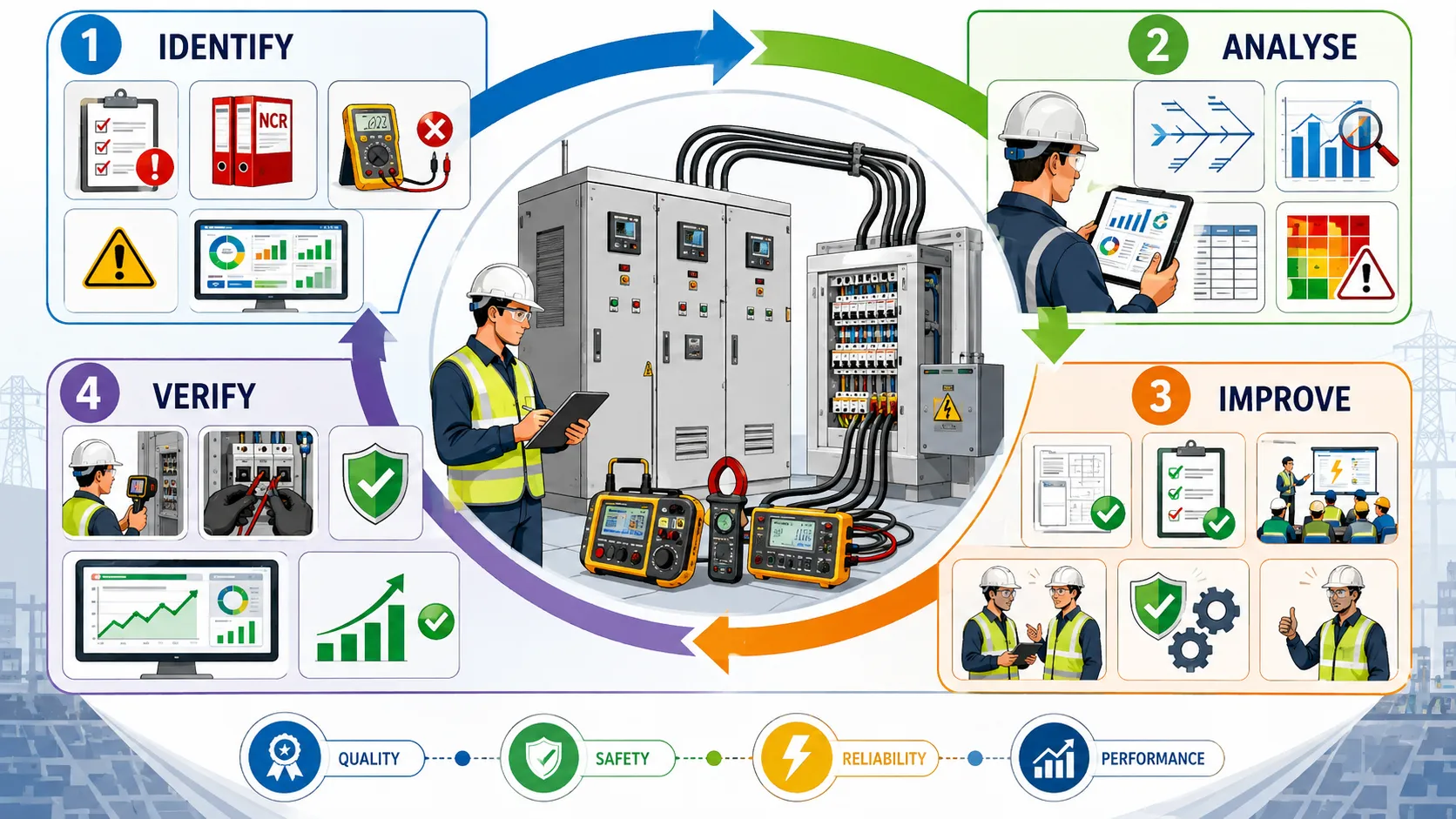
Understanding Continuous Improvement in Electrical QA/QC
Continuous improvement is the systematic process of identifying opportunities to improve electrical quality, safety, reliability, efficiency, compliance, and performance over time.
It involves an ongoing cycle of:
- Identifying quality or safety information.
- Analysing performance.
- Establishing priorities.
- Developing improvement actions.
- Implementing approved changes.
- Monitoring results.
- Verifying effectiveness.
- Standardising successful improvements.
- Reviewing further opportunities.
Continuous improvement should not be interpreted as making constant changes without control. Uncontrolled changes can introduce new risks. Improvement must therefore be managed through appropriate engineering, QA/QC, document-control, change-management, and verification processes.
Quality Improvement and Safety Improvement
Quality and safety are closely connected within electrical systems.
A quality failure may affect safety when it involves:
- Incorrect installation.
- Defective components.
- Poor cable termination.
- Inadequate protection.
- Incorrect equipment identification.
- Unsatisfactory testing.
- Poor earthing arrangements.
- Inadequate documentation.
- Incorrect design information.
Similarly, safety concerns can reveal underlying quality weaknesses.
For example, repeated overheating at electrical connections may indicate:
- Poor termination quality.
- Incorrect torque application.
- Inadequate inspection.
- Incorrect component selection.
- Poor maintenance.
- Inadequate monitoring.
Therefore, improvement activities should consider both quality and safety rather than treating them as completely separate objectives.
Key Concepts for Continuous Electrical Improvement
Continual Improvement
Continual improvement involves ongoing, structured efforts to enhance processes and performance using evidence, lessons learned, monitoring, and review.
It may focus on:
- Reducing defects.
- Improving inspection effectiveness.
- Improving test performance.
- Strengthening documentation.
- Improving reliability.
- Reducing rework.
- Improving safety controls.
- Strengthening competence.
Quality Performance
Quality performance represents how effectively electrical work and systems meet defined requirements.
Performance can be assessed using:
- Inspection acceptance rates.
- NCR trends.
- Test pass rates.
- Rework levels.
- Audit findings.
- Defect recurrence.
- Commissioning performance.
- Maintenance findings.
Safety Performance
Safety performance concerns the ability of the electrical system and associated work processes to prevent unacceptable electrical hazards and unsafe conditions.
Relevant indicators may include:
- Unsafe installation findings.
- Electrical incident trends.
- Repeated safety observations.
- Protection-related deficiencies.
- Equipment condition.
- Corrective action performance.
Lessons Learned
Lessons learned are knowledge obtained from completed activities, failures, successes, inspections, testing, commissioning, audits, and operational experience that can improve future performance.
A lesson becomes valuable when it is converted into an actionable improvement.
Performance Indicator
A performance indicator is a measurable factor used to evaluate quality or safety performance.
Examples include:
- NCR frequency.
- First-pass inspection acceptance.
- Rework percentage.
- Test failure rate.
- Corrective action closure time.
- Repeat finding frequency.
- Audit non-conformity trends.
Framework for Continuous Electrical Quality Improvement
A practical improvement cycle can be structured as:
Identify → Analyse → Prioritise → Plan → Implement → Verify → Standardise → Review
Each stage has a specific purpose.
Identify
Identify quality or safety concerns using reliable evidence.
Sources may include:
- Inspection findings.
- Testing.
- NDE.
- NCRs.
- Audits.
- Commissioning.
- Maintenance.
- Incidents.
- Client feedback.
- Supplier performance.
Analyse
Determine what the information means.
The QA/QC Engineer should consider:
- Frequency.
- Severity.
- Location.
- Equipment.
- Contractor.
- Process.
- Root cause.
- Recurrence.
- Potential consequences.
Prioritise
Not every improvement opportunity has the same importance.
Prioritisation should consider:
- Safety.
- Electrical system criticality.
- Risk.
- Compliance.
- Reliability.
- Cost.
- Programme.
- Recurrence.
Plan
Develop a controlled improvement action.
The plan should define:
- Required change.
- Responsible person.
- Resources.
- Target date.
- Verification method.
- Performance indicator.
Implement
Introduce the approved improvement using appropriate controls.
Verify
Determine whether the improvement achieved its intended result.
Standardise
Where successful, incorporate the improvement into:
- Procedures.
- Inspection plans.
- Training.
- Checklists.
- Design standards.
- Quality processes.
Review
Continue monitoring to determine whether performance remains stable.
Sources of Improvement Opportunities
Electrical QA/QC professionals should use multiple information sources rather than relying only on NCRs.
Inspection Data
Inspection records can reveal:
- Recurring defects.
- Weak installation areas.
- Repeated workmanship issues.
- Documentation gaps.
- Inspection process limitations.
Testing and Commissioning Data
Testing can identify:
- Equipment performance problems.
- Installation deficiencies.
- Protection issues.
- Repeated failures.
- Inconsistent test results.
NCR Trends
NCR analysis can reveal:
- Recurring defects.
- Contractor weaknesses.
- Process deficiencies.
- Supplier problems.
- Ineffective corrective actions.
Audit Findings
Audits can identify weaknesses in:
- Procedures.
- Document control.
- Inspection planning.
- Corrective action.
- Management processes.
Operational and Maintenance Feedback
After commissioning, maintenance teams may identify:
- Recurring equipment failures.
- Overheating.
- Loose connections.
- Component degradation.
- Access difficulties.
- Documentation inaccuracies.
This information can be used to improve future projects and existing systems.
Using Data to Drive Improvement
Continuous improvement should be evidence-based.
A QA/QC Engineer should avoid recommendations based solely on assumptions such as:
- “The contractor needs more inspections.”
- “The workers need more training.”
- “The procedure is not being followed.”
Instead, evidence should establish the reason for the recommendation.
For example:
If inspection data shows that 70% of cable termination defects occur during one installation stage, the engineer can investigate that stage specifically.
Useful data may include:
- Number of inspections.
- Number of failures.
- Defect categories.
- Defect locations.
- Contractor performance.
- Equipment types.
- Inspection dates.
- Test results.
- Rework frequency.
Developing Priorities for Improvement
Improvement activities should be prioritised according to their potential impact.
High-Priority Improvements
These may involve:
- Electrical safety.
- Critical protection systems.
- Repeated major defects.
- Serious testing failures.
- Widespread non-conformity.
- Critical equipment reliability.
- Significant compliance concerns.
Medium-Priority Improvements
Examples include:
- Recurring workmanship issues.
- Documentation weaknesses.
- Moderate supplier issues.
- Repeated minor NCRs.
Lower-Priority Improvements
These may include:
- Minor administrative inefficiencies.
- Non-critical formatting issues.
- Small process improvements.
The classification should always reflect the project context and risk profile.
Improving Inspection Effectiveness
Inspection itself should also be subject to continuous improvement.
The QA/QC Engineer can review:
- Whether inspections occur at the correct stages.
- Whether inspection criteria are sufficiently clear.
- Whether hold points are effective.
- Whether inspectors have appropriate information.
- Whether sampling is adequate.
- Whether inspection records capture necessary evidence.
- Whether recurring defects are being detected early.
Possible improvements include:
- Revising Inspection and Test Plans.
- Strengthening hold points.
- Introducing first-off inspections.
- Improving inspection checklists.
- Increasing targeted sampling.
- Improving inspection training.
- Introducing trend reviews.
Improving Electrical Testing Processes
Testing provides important evidence about electrical quality and system performance.
Continuous improvement may involve:
- Reviewing test procedures.
- Improving test preparation.
- Ensuring appropriate test equipment.
- Strengthening test-record traceability.
- Reviewing recurring failures.
- Improving test coordination.
- Establishing readiness criteria.
Where repeated test failures occur, the QA/QC Engineer should determine whether the issue originates from:
- Installation.
- Equipment.
- Testing method.
- Environment.
- Test equipment.
- Personnel.
- Documentation.
Improving Installation Quality
Installation quality can be improved through controlled processes.
Potential measures include:
- Clear installation procedures.
- Competency verification.
- First-off inspection.
- Increased supervision for critical activities.
- Visual installation guides.
- Defined acceptance criteria.
- Better coordination between engineering and construction teams.
- Early inspection of representative work.
The purpose is to identify problems before large quantities of work are completed.
Improving Electrical Component Quality
Component-related quality can be improved through stronger controls throughout the supply chain.
These may include:
- Approved supplier evaluation.
- Material approval.
- Incoming inspection.
- Certificate verification.
- Storage controls.
- Handling requirements.
- Component identification.
- Traceability.
- Supplier performance monitoring.
Where a supplier repeatedly provides defective components, supplier performance should be reviewed rather than repeatedly correcting the same issue on site.
Improving Documentation and Traceability
Documentation is a major component of electrical quality assurance.
Improvement actions may include:
- Standardising inspection forms.
- Improving equipment identification.
- Strengthening revision control.
- Linking inspection findings to drawings.
- Linking test results to equipment.
- Improving NCR traceability.
- Introducing controlled electronic records.
- Reviewing document completeness.
A well-designed documentation system should help personnel and auditors answer:
- What was inspected?
- When was it inspected?
- Against which requirement?
- Who inspected it?
- What was found?
- What action was taken?
- How was the action verified?
Improving Competence and Workforce Performance
Human competence is an important quality factor.
Where evidence indicates competence-related weaknesses, improvement may involve:
- Task-specific training.
- Practical competency assessments.
- Refresher training.
- Toolbox briefings.
- Supervisor development.
- Technical demonstrations.
- Lessons-learned sessions.
However, training should not be used as the automatic response to every defect.
The QA/QC Engineer should first determine whether the actual cause involves:
- Competence.
- Procedure.
- Equipment.
- Design.
- Supervision.
- Communication.
Improving Supervision
Effective supervision can help ensure that approved requirements are implemented consistently.
Supervisory improvements may include:
- Defined inspection responsibilities.
- Supervisor check points.
- Review of critical activities.
- First-off verification.
- Monitoring of recurring findings.
- Increased oversight where quality performance is weak.
The objective should be targeted supervision rather than unnecessary duplication.
Improving Design Quality
Some construction defects originate in design information rather than installation.
Continuous improvement may therefore include:
- Design reviews.
- Constructability reviews.
- Interface coordination.
- Design verification.
- Improved drawing details.
- Better equipment schedules.
- Controlled design revisions.
- Feedback from construction and commissioning.
Design-related lessons should be communicated into future design processes.
Improving Supplier and Contractor Performance
Supplier and contractor quality should be monitored using objective performance data.
Relevant indicators may include:
- NCR frequency.
- Inspection rejection rate.
- Repeat findings.
- Corrective action performance.
- Test failures.
- Documentation quality.
- Response time.
Where performance is consistently below expectations, improvement actions may include:
- Targeted technical meetings.
- Supplier corrective action.
- Increased inspection.
- Competency review.
- Process audits.
- Performance improvement plans.
Practical Example: Improving Cable Installation Quality
A project identifies a recurring pattern of cable installation defects.
The QA/QC Engineer analyses inspection records and discovers:
- Repeated routing deviations.
- Incorrect identification.
- Poor support spacing.
- Inconsistent termination quality.
Rather than issuing separate NCRs indefinitely, the engineer develops a quality improvement programme.
The programme includes:
- Reviewing the installation procedure.
- Improving visual installation guidance.
- Conducting targeted workforce briefings.
- Introducing first-off cable installation inspection.
- Increasing supervision during critical stages.
- Reviewing inspection trends weekly.
The result is monitored using first-pass acceptance and NCR frequency.
If the defect rate decreases consistently, the improved controls can be integrated into the standard installation process.
Practical Example: Improving Switchboard Quality
During commissioning, several switchboards require additional corrective work because of documentation and installation discrepancies.
The QA/QC Engineer reviews:
- Factory records.
- Installation inspections.
- Testing documents.
- Drawing revisions.
- NCR history.
- Commissioning feedback.
The analysis reveals that several problems resulted from poor coordination between design revisions and site installation.
The improvement programme may include:
- Strengthening design-change communication.
- Improving drawing revision control.
- Introducing pre-commissioning document reviews.
- Establishing equipment-specific quality dossiers.
- Conducting pre-energisation verification.
This approach addresses the process rather than repeatedly correcting individual discrepancies.
Practical Example: Improving Electrical Testing Performance
An industrial project experiences repeated failed electrical tests.
The QA/QC Engineer identifies that failures are concentrated around a particular installation stage.
The investigation examines:
- Installation quality.
- Test preparation.
- Test equipment.
- Environmental conditions.
- Personnel competence.
The improvement programme introduces:
- Pre-test readiness checks.
- Improved test procedures.
- Equipment identification verification.
- Test equipment checks.
- Increased coordination between installation and testing teams.
- Review of test trends.
The objective is to improve first-pass testing rather than simply increase the number of retests.
Practical Example: Improving Documentation Quality
An audit identifies repeated missing information in inspection records.
The QA/QC team reviews the documentation process and determines that the existing form does not require several critical fields.
Improvements include:
- Revising the inspection form.
- Adding mandatory equipment identification.
- Adding drawing revision fields.
- Including acceptance criteria.
- Linking NCR references.
- Providing inspector guidance.
- Conducting periodic sample audits.
The effectiveness of the improvement is measured by tracking documentation-related findings in subsequent audits.
Integrating Quality and Safety Improvements
Quality and safety improvement should be considered together.
For example, repeated loose electrical connections are a quality problem that may also create safety and reliability consequences.
Improvement may include:
- Reviewing termination procedures.
- Strengthening torque requirements.
- Improving tool control.
- Introducing verification records.
- Increasing inspection at critical stages.
- Reviewing similar installations.
This demonstrates how a quality finding can become an opportunity to improve electrical safety.
Using the PDCA Approach
A useful continuous improvement model is the Plan-Do-Check-Act cycle.
Plan
Identify the problem and determine the improvement objective.
For example:
“Reduce recurring cable termination defects.”
Do
Implement the improvement.
For example:
- Revise procedure.
- Train personnel.
- Introduce first-off inspection.
Check
Measure results.
For example:
- Compare defect rates.
- Review NCR trends.
- Examine inspection acceptance.
Act
If successful, standardise the improvement.
If unsuccessful:
- Reassess the root cause.
- Modify the control.
- Conduct further analysis.
The cycle can then continue.
Measuring Improvement Effectiveness
A recommendation should ideally have measurable outcomes.
Useful indicators include:
| Improvement Area | Possible Indicator | Evidence of Improvement |
|---|---|---|
| Installation quality | Inspection rejection rate | Fewer rejected installations |
| Testing | Test failure rate | Higher first-pass test rate |
| NCR management | Repeat NCR frequency | Reduced recurrence |
| Documentation | Documentation findings | Fewer incomplete records |
| Safety | Electrical safety observations | Reduced recurring observations |
| Supplier quality | Material-related NCRs | Fewer supplier defects |
| Rework | Rework percentage | Reduced corrective work |
| Competence | Competency assessment results | Improved task performance |
| Inspection | First-pass acceptance | Increased conformity |
| Corrective action | Repeat findings | Reduced recurrence |
Indicators should be selected according to the nature of the improvement.
Monitoring Improvement Performance
Monitoring should be planned rather than informal.
The QA/QC Engineer may establish:
- Weekly quality reviews.
- Monthly trend analysis.
- Project quality dashboards.
- NCR trend meetings.
- Supplier performance reviews.
- Inspection performance reviews.
- Audit follow-ups.
Monitoring should focus on meaningful information rather than producing unnecessary reports.
Managing Improvement Through Controlled Change
Improvement activities may require changes to:
- Drawings.
- Procedures.
- Inspection plans.
- Checklists.
- Equipment.
- Installation methods.
- Testing procedures.
- Training.
Such changes should be appropriately controlled.
Before implementation, consider:
- Technical impact.
- Safety impact.
- Quality impact.
- Programme impact.
- Documentation requirements.
- Training needs.
- Approval requirements.
After implementation, verify that affected personnel are using the revised information.
Capturing Lessons Learned
Lessons learned should be captured before project knowledge is lost.
Useful lessons may come from:
- Major NCRs.
- Repeated defects.
- Successful corrective actions.
- Commissioning challenges.
- Audit findings.
- Supplier issues.
- Testing failures.
- Safety observations.
A useful lesson should identify:
- What happened?
- Why did it happen?
- What was changed?
- What was learned?
- Where should the lesson be applied?
Lessons should be incorporated into future procedures, training, design reviews, and project planning where relevant.
Common Barriers to Continuous Improvement
Resistance to Change
Personnel may resist new procedures because they are familiar with existing methods.
The response should include:
- Clear communication.
- Evidence of benefit.
- Appropriate training.
- Management support.
Poor Quality Data
Improvement decisions are weakened when inspection records are incomplete or inconsistent.
Lack of Ownership
An improvement without an assigned owner may not progress.
Excessive Administrative Burden
Too many forms can reduce efficiency without improving quality.
Weak Effectiveness Monitoring
Without measurement, it may be impossible to determine whether an improvement worked.
Failure to Standardise
Successful improvements may be lost if they are not incorporated into controlled processes.
Roles and Responsibilities
Electrical QA/QC Engineer
The Electrical QA/QC Engineer may:
- Analyse quality data.
- Identify improvement opportunities.
- Evaluate trends.
- Recommend actions.
- Coordinate investigations.
- Monitor effectiveness.
- Report performance.
Site Management
Management may:
- Provide resources.
- Support implementation.
- Remove organisational barriers.
- Review performance.
Electrical Supervisors
Supervisors may:
- Implement improved procedures.
- Monitor workforce performance.
- Reinforce requirements.
- Report recurring issues.
Design Team
The design team may:
- Review design-related issues.
- Clarify requirements.
- Control revisions.
- Incorporate lessons learned.
Contractors and Suppliers
They may:
- Implement agreed improvements.
- Provide evidence.
- Participate in investigations.
- Improve their processes.
Case Study: Continuous Improvement of an Electrical Distribution System
Project Background
An industrial facility is installing a complex electrical distribution system containing switchboards, transformers, cable systems, protection equipment, control systems, and associated infrastructure.
During construction and commissioning, the QA/QC team identifies several recurring issues.
These include:
- Cable termination defects.
- Incomplete inspection records.
- Repeated testing failures.
- Incorrect equipment identification.
- Delayed NCR closure.
Initial Analysis
The Electrical QA/QC Engineer reviews several months of quality data.
The review identifies that the problems are interconnected.
For example:
- Installation defects contribute to test failures.
- Documentation weaknesses make traceability difficult.
- Poor identification increases commissioning delays.
- Delayed NCR closure reduces visibility of unresolved issues.
Improvement Programme
The team establishes several actions:
- Review critical installation procedures.
- Introduce first-off inspections.
- Improve equipment identification controls.
- Strengthen testing readiness checks.
- Revise inspection forms.
- Introduce weekly NCR trend reviews.
- Improve contractor technical briefings.
- Establish effectiveness indicators.
Measurement
The project tracks:
- First-pass inspection acceptance.
- Test failure rate.
- Repeat NCRs.
- Documentation errors.
- NCR closure performance.
Review
After implementation, the QA/QC team compares the new performance with the previous baseline.
The results demonstrate improved inspection acceptance, fewer repeated findings, improved documentation quality, and better test performance.
Standardisation
Successful improvements are incorporated into:
- Controlled procedures.
- Inspection plans.
- Training.
- Project quality processes.
- Future project planning.
Case Study Conclusion
The case demonstrates that continuous improvement is most effective when quality information is considered as an integrated system. Instead of treating every defect separately, the organisation identifies relationships between installation, testing, documentation, and management controls. This produces a stronger improvement strategy and supports sustainable electrical quality.
Benefits of Continuous Electrical Quality and Safety Improvement
Continuous improvement provides significant benefits across the project lifecycle.
Improved Electrical Safety
Better controls can reduce the likelihood of unsafe electrical conditions.
Improved Reliability
Improved installation and testing processes can increase equipment reliability.
Reduced Defects
Trend analysis allows recurring problems to be identified earlier.
Reduced Rework
Improving quality at source reduces repeated correction.
Reduced Project Disruption
Early identification of problems can reduce commissioning and handover delays.
Better Compliance
Controlled processes improve conformity with applicable project requirements.
Stronger Audit Performance
Evidence-based improvement demonstrates an effective quality management culture.
Better Client Confidence
Clients benefit from a system that demonstrates learning and measurable improvement.
Improved Workforce Competence
Lessons learned and targeted training improve technical capability.
Better Long-Term Asset Performance
Quality improvements implemented during construction can contribute to improved operation and maintenance performance.
Continuous Improvement Review Checklist
Before implementing an improvement, the QA/QC Engineer should consider:
- What quality or safety issue has been identified?
- What evidence supports the issue?
- Is the problem recurring?
- What is the potential consequence?
- What is the likely root cause?
- Which parts of the electrical system are affected?
- Is the proposed improvement technically appropriate?
- Is the action proportionate to risk?
- Who owns the action?
- What resources are required?
- What documents require revision?
- What training is required?
- How will implementation be verified?
- What performance indicator will be monitored?
- When will effectiveness be reviewed?
- How will successful improvements be standardised?
- What happens if the improvement is ineffective?
Conclusion
Implementing practical improvements to continuously enhance electrical system quality and safety requires a structured combination of inspection analysis, professional judgement, risk assessment, corrective action, preventive control, performance monitoring, and organisational learning. Electrical QA/QC professionals should not treat inspection findings, NCRs, testing failures, audit observations, commissioning problems, or maintenance feedback as isolated administrative events. These sources provide valuable information about how effectively the electrical quality system is functioning and where improvements can be made.
A strong improvement process begins by identifying the issue accurately and analysing objective evidence. The QA/QC Engineer should determine the frequency, severity, recurrence, affected equipment, potential consequences, and contributing factors. This information supports prioritisation and helps ensure that resources are directed towards the areas where improvement can have the greatest effect. Actions should then be clearly defined, assigned, implemented, and verified.
Continuous improvement should address the complete electrical quality lifecycle. Design information, procurement, material control, installation, inspection, testing, commissioning, documentation, training, supervision, and maintenance can all influence final electrical performance. Improvements made in one area may therefore affect another. For example, improved design information can reduce installation defects, stronger installation controls can improve testing results, and better documentation can improve commissioning and future maintenance.
Measurement is essential to determine whether improvement actions are effective. Indicators such as first-pass inspection acceptance, test failure rates, recurring NCRs, rework, documentation findings, supplier performance, and corrective action recurrence can provide objective evidence of progress. If the expected improvement is not achieved, the QA/QC team should reassess the root cause and modify the approach rather than assuming that implementation alone is sufficient.
The ultimate objective is to establish a culture in which electrical quality and safety continuously improve through evidence and learning. When inspection outcomes are systematically analysed, lessons learned are captured, successful improvements are standardised, and performance is monitored, organisations can reduce recurring defects, improve reliability, strengthen safety, minimise rework, improve commissioning and handover, and increase confidence in electrical system performance. For a Level 6 Electrical QA/QC professional, this represents a transition from reactive defect management to proactive quality leadership, where inspection information becomes a strategic tool for improving the safety, reliability, compliance, and long-term performance of electrical system