
Lesson 1: Inspection and Testing Techniques in Mechanical Engineering
Inspection and testing techniques are the backbone of quality assurance (QA) and quality control (QC) in mechanical engineering, ensuring that materials, fabricated components, equipment, and completed systems consistently meet engineering specifications, regulatory requirements, and customer expectations. Every stage of a mechanical engineering project from raw material inspection and manufacturing to installation, commissioning, and maintenance relies on accurate inspection methods and reliable testing procedures to verify quality, detect defects, and minimise the risk of equipment failure. Effective inspection not only improves product reliability and operational performance but also reduces rework, downtime, and lifecycle costs while supporting compliance with international quality standards such as ISO 9001, ASME, ASTM, API, and relevant engineering codes.
This lesson provides a comprehensive understanding of the inspection and testing techniques widely used in mechanical engineering industries, including visual inspection, dimensional inspection, mechanical testing, pressure testing, leak testing, and both destructive and non-destructive testing (NDT) methods. Learners will explore the principles, applications, advantages, and limitations of each technique, along with the selection and proper use of precision measuring instruments such as vernier calipers, micrometers, dial indicators, height gauges, and coordinate measuring machines (CMMs). The lesson also explains how inspection planning, calibration, sampling procedures, acceptance criteria, and documentation contribute to an effective Quality Management System (QMS), ensuring traceability and consistency throughout the production process.
From the perspective of a QA/QC Mechanical Engineer, inspection is not merely the identification of defects but a systematic process of verifying that engineering work complies with approved drawings, technical specifications, Inspection and Test Plans (ITPs), Welding Procedure Specifications (WPS), quality procedures, and client requirements. Mechanical inspectors play a critical role in monitoring fabrication quality, supervising welding inspections, validating material certifications, witnessing pressure tests, reviewing inspection records, and ensuring compliance with project quality standards. Through structured inspection activities, organisations can prevent costly failures, improve customer satisfaction, enhance workplace safety, and maintain regulatory compliance across manufacturing plants, oil and gas facilities, power generation projects, construction sites, and industrial maintenance operations.
By the end of this lesson, learners will have developed a strong foundation in modern inspection and testing techniques used within mechanical engineering. They will understand how to select appropriate inspection methods for different engineering applications, interpret inspection and test results accurately, prepare quality documentation, and implement best practices that support continuous improvement. These competencies are essential for aspiring QA/QC Engineers, Mechanical Inspectors, Production Engineers, Maintenance Engineers, Welding Inspectors, and quality professionals responsible for delivering safe, reliable, and high-quality mechanical engineering products and systems.
1. Identify Different Inspection Techniques and Testing Methods Used in Mechanical Engineering, Such as Visual Inspection, Dimensional Measurement, and Functional Testing
Inspection and testing are among the most important quality assurance (QA) and quality control (QC) activities in mechanical engineering. Every mechanical component, machine, structure, or system must be inspected and tested to ensure it complies with engineering drawings, technical specifications, client requirements, and international quality standards before it is accepted for service. Regardless of whether a product is manufactured in a fabrication workshop, assembled in a production facility, or installed at a construction site, systematic inspection and testing help verify that it performs safely, efficiently, and reliably throughout its intended service life.
As a QA/QC Mechanical Engineer, inspection is much more than identifying defects. It is a structured process of verifying quality at every stage of manufacturing, fabrication, installation, and commissioning. Effective inspection ensures that materials are suitable, dimensions are accurate, welding is acceptable, assemblies function correctly, and completed systems meet contractual and regulatory requirements. Inspection activities reduce costly rework, improve customer confidence, increase equipment reliability, and contribute to continuous quality improvement.
Testing complements inspection by evaluating whether a component or system performs according to its intended design and operational requirements. While inspection primarily identifies visible or measurable characteristics, testing determines the mechanical, physical, functional, or operational performance of engineering products. Together, inspection and testing provide objective evidence that products conform to specified quality standards before they are delivered to clients or placed into operation.
For modern industries such as oil and gas, petrochemical, manufacturing, power generation, aerospace, marine engineering, automotive production, and heavy engineering, inspection and testing are essential quality management tools. International standards such as ISO 9001, ASME, ASTM, API, ISO 17025, ISO 9712, and various national engineering codes require organisations to establish documented inspection and testing procedures that ensure product quality and regulatory compliance.
Importance of Inspection and Testing in Mechanical Engineering
Inspection and testing provide confidence that engineering products meet specified requirements before they enter service.
Their importance includes:
- Verifying compliance with engineering drawings.
- Confirming conformity with customer specifications.
- Ensuring manufactured products meet design tolerances.
- Detecting manufacturing defects at an early stage.
- Preventing failures during operation.
- Improving workplace safety.
- Increasing equipment reliability.
- Supporting regulatory compliance.
- Reducing production waste.
- Minimising repair and replacement costs.
- Improving customer satisfaction.
- Supporting continual improvement initiatives.
- Providing documented evidence of quality.
- Enhancing organisational reputation.
- Increasing product lifespan.
Relationship Between Inspection and Testing
Although inspection and testing are closely related, they serve different purposes within a Quality Management System (QMS).
Inspection is primarily concerned with determining whether a product meets specified physical characteristics, dimensions, workmanship standards, and documented requirements. Testing, on the other hand, evaluates whether the product performs as intended under defined operating conditions.
Both activities work together throughout the product lifecycle to ensure that only compliant products progress to the next manufacturing stage or are released to the customer.
Key Objectives of Mechanical Inspection
The primary objectives of mechanical inspection include:
- Confirm material conformity.
- Verify manufacturing quality.
- Detect defects before product delivery.
- Ensure dimensional accuracy.
- Confirm assembly correctness.
- Verify compliance with project specifications.
- Maintain production consistency.
- Support quality assurance programmes.
- Reduce operational failures.
- Protect customer interests.
- Ensure compliance with international standards.
-
Improve manufacturing efficiency.

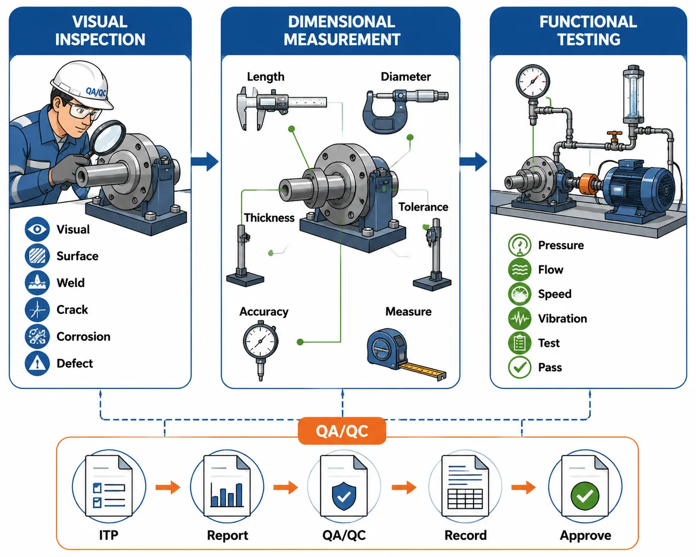
Visual Inspection
Definition of Visual Inspection
Visual Inspection (VT) is the simplest, most frequently used, and most cost-effective inspection technique in mechanical engineering. It involves carefully examining components, assemblies, welds, machinery, piping systems, or fabricated structures using the human eye, often supported by optical devices such as magnifying glasses, mirrors, borescopes, fibrescopes, endoscopes, or digital cameras.
Visual inspection is normally the first inspection activity performed before more advanced inspection or testing methods are applied. Many manufacturing defects can be identified immediately through systematic visual examination without requiring expensive equipment.
Purpose of Visual Inspection
Visual inspection aims to identify obvious defects, verify workmanship quality, and ensure that components comply with engineering requirements before additional inspections are performed.
It is commonly used to:
- Detect surface defects.
- Verify weld appearance.
- Check surface finish quality.
- Confirm correct assembly.
- Inspect coatings and paint quality.
- Detect corrosion.
- Identify deformation.
- Verify component orientation.
- Check cleanliness.
- Confirm marking and identification.
- Verify documentation.
- Monitor fabrication progress.
Visual Inspection Procedure
A professional QA/QC Mechanical Engineer generally follows a structured inspection procedure.
The process includes:
Preparation
- Review engineering drawings.
- Study inspection procedures.
- Verify acceptance criteria.
- Gather inspection tools.
- Ensure adequate lighting.
- Confirm inspection safety requirements.
Inspection
- Examine the overall component condition.
- Inspect surfaces carefully.
- Observe weld profiles.
- Check joints and connections.
- Verify dimensions visually.
- Inspect fasteners.
- Confirm identification markings.
- Examine protective coatings.
Evaluation
- Compare findings with specifications.
- Identify acceptable conditions.
- Record defects.
- Photograph non-conformities.
- Prepare inspection reports.
Common Defects Identified During Visual Inspection
Visual inspection can detect numerous manufacturing and fabrication problems.
Examples include:
- Surface cracks
- Weld undercut
- Porosity
- Excessive reinforcement
- Incomplete weld fusion
- Corrosion
- Rust
- Surface scratches
- Dents
- Distortion
- Misalignment
- Incorrect assembly
- Missing fasteners
- Paint defects
- Coating damage
- Leakage signs
- Improper identification
- Mechanical damage
Advantages of Visual Inspection
Visual inspection remains one of the most valuable inspection techniques because it offers several practical advantages.
These include:
- Simple implementation.
- Low inspection cost.
- Rapid inspection process.
- Immediate defect identification.
- Minimal equipment requirements.
- Applicable throughout production.
- Supports preventive maintenance.
- Can be combined with other inspection methods.
- Suitable for large structures.
- Provides early quality feedback.
Limitations of Visual Inspection
Despite its usefulness, visual inspection has limitations.
These include:
- Only detects surface defects.
- Cannot identify internal flaws.
- Depends heavily on inspector experience.
- Influenced by lighting conditions.
- May overlook microscopic defects.
- Requires accessible inspection areas.
Dimensional Measurement
Definition
Dimensional measurement is the process of determining the physical size, shape, geometry, and positional accuracy of mechanical components using calibrated measuring instruments.
Every engineering drawing specifies dimensional tolerances that manufactured parts must satisfy. If dimensions exceed allowable tolerances, the product may fail during assembly or operation.
Dimensional inspection therefore ensures that manufactured components meet specified design requirements before progressing to the next production stage.
Importance of Dimensional Measurement
Accurate dimensional measurement ensures compatibility between mating parts and guarantees proper assembly, performance, and interchangeability.
It helps organisations:
- Prevent assembly problems.
- Maintain manufacturing consistency.
- Improve production quality.
- Reduce scrap.
- Minimise rework.
- Improve machine performance.
- Ensure interchangeability.
- Support process control.
- Verify machining accuracy.
- Meet customer specifications.
Common Measuring Instruments Used
QA/QC Mechanical Engineers use a variety of precision instruments depending on the required measurement accuracy.
Common instruments include:
- Steel rule
- Measuring tape
- Vernier caliper
- Digital caliper
- Outside micrometer
- Inside micrometer
- Depth micrometer
- Height gauge
- Dial indicator
- Feeler gauge
- Bore gauge
- Thread gauge
- Radius gauge
- Surface plate
- Coordinate Measuring Machine (CMM)
- Laser measuring system
- Optical comparator
Dimensional Inspection Process
Professional dimensional inspection normally follows these steps:
Step 1: Review Documentation
- Engineering drawings
- Manufacturing specifications
- Tolerance requirements
- Inspection plan
Step 2: Verify Equipment
- Check calibration status.
- Clean measuring instruments.
- Confirm instrument accuracy.
- Select appropriate measuring tools.
Step 3: Perform Measurements
- Measure critical dimensions.
- Verify hole diameters.
- Check thickness.
- Measure length.
- Inspect flatness.
- Verify perpendicularity.
- Confirm concentricity.
- Measure angular dimensions.
Step 4: Record Results
- Compare measurements with tolerances.
- Document inspection findings.
- Identify deviations.
- Prepare inspection reports.
Comparison of Major Mechanical Inspection Techniques
| Inspection Technique | Definition | Key Concepts | Detailed Explanation | Typical Applications | Main Benefits |
|---|---|---|---|---|---|
| Visual Inspection (VT) | Examination of components using direct or assisted visual observation. | Surface quality, workmanship, visible defects. | Detects cracks, corrosion, distortion, poor weld appearance, coating defects, and assembly issues without damaging the component. | Welding, fabrication, piping, structural steel, pressure vessels. | Fast, economical, easy to perform, detects obvious defects early. |
| Dimensional Measurement | Verification of component dimensions using calibrated precision measuring instruments. | Accuracy, tolerances, calibration, geometry. | Confirms that manufactured parts conform to engineering drawings and specified dimensional limits. | Machining, manufacturing, fabrication, assembly, precision engineering. | Ensures proper fit, improves product quality, reduces rework, supports interchangeability. |
| Functional Testing | Evaluation of a component or system under operating conditions to verify its intended performance. | Performance verification, operational reliability, system functionality. | Confirms that equipment performs safely and efficiently according to design specifications before commissioning or delivery. | Pumps, valves, compressors, rotating equipment, hydraulic and pneumatic systems. | Verifies operational performance, improves reliability, reduces failure risk, enhances customer confidence. |
Functional Testing
Definition of Functional Testing
Functional testing is a systematic quality control process used to verify that a mechanical component, assembly, machine, or complete system performs according to its intended design, engineering specifications, and operational requirements. Unlike visual inspection and dimensional measurement, which focus on physical characteristics and geometry, functional testing evaluates how a product behaves under actual or simulated operating conditions.
From a QA/QC Mechanical Engineer’s perspective, functional testing provides objective evidence that equipment is capable of performing its intended function safely, efficiently, and consistently before being released for installation, commissioning, or customer acceptance. Functional testing is typically performed after fabrication, machining, assembly, or installation has been completed and all preliminary inspections have been successfully passed.
A properly executed functional test confirms that individual components work together as an integrated system and that the equipment can operate within its specified performance limits. It also helps identify hidden operational problems that cannot be detected through visual inspection or dimensional measurement alone.
Objectives of Functional Testing
The primary objective of functional testing is to demonstrate that mechanical equipment operates as intended under defined operating conditions.
Key objectives include:
- Verify operational performance.
- Confirm design functionality.
- Validate engineering specifications.
- Ensure safe equipment operation.
- Identify operational defects.
- Detect abnormal vibration.
- Verify pressure performance.
- Confirm flow characteristics.
- Measure operational efficiency.
- Evaluate mechanical reliability.
- Verify automatic control functions.
- Confirm emergency shutdown operation.
- Ensure customer requirements are satisfied.
- Reduce commissioning failures.
- Improve long-term equipment reliability.
Types of Functional Testing in Mechanical Engineering
QA/QC engineers apply different functional testing methods depending on the type of equipment and project requirements.
Common functional tests include:
Operational Testing
Operational testing verifies that machinery performs correctly during normal operating conditions.
Examples include:
- Pump operation
- Compressor operation
- Gearbox rotation
- Conveyor operation
- Motor performance
- Valve movement
- Mechanical actuators
Pressure Testing
Pressure testing verifies the strength and leak-tightness of pressure-containing equipment.
Applications include:
- Pressure vessels
- Pipelines
- Boilers
- Heat exchangers
- Storage tanks
- Hydraulic systems
Common methods:
- Hydrostatic testing
- Pneumatic testing
Leak Testing
Leak testing identifies unwanted leakage from sealed systems.
Examples include:
- Gas pipelines
- Fuel systems
- Hydraulic circuits
- Pneumatic systems
- Refrigeration systems
Load Testing
Load testing evaluates equipment under designed loading conditions.
Applications include:
- Lifting equipment
- Cranes
- Hoists
- Structural supports
- Mechanical frames
Performance Testing
Performance testing determines whether equipment achieves its specified operational capacity.
Performance parameters include:
- Output capacity
- Pressure
- Temperature
- Efficiency
- Flow rate
- Speed
- Power consumption
- Fuel consumption
General Functional Testing Procedure
A systematic functional testing procedure improves consistency and reliability.
Step 1: Review Technical Documentation
Before testing begins, QA/QC personnel should review:
- Engineering drawings
- Technical specifications
- Inspection and Test Plan (ITP)
- Equipment manuals
- Client requirements
- Acceptance criteria
Step 2: Verify Equipment Readiness
Before conducting the test:
- Confirm assembly completion.
- Verify calibration certificates.
- Check safety devices.
- Inspect lubrication systems.
- Confirm electrical connections.
- Ensure all fasteners are tightened.
Step 3: Conduct Functional Test
During testing:
- Start equipment gradually.
- Monitor operating conditions.
- Observe abnormal behaviour.
- Measure performance values.
- Record operating parameters.
- Compare results with specifications.
Step 4: Evaluate Results
The QA/QC engineer evaluates:
- Compliance with specifications.
- Equipment stability.
- Safety performance.
- Operational efficiency.
- Acceptance criteria.
Step 5: Documentation
The final stage includes:
- Functional test reports.
- Inspection records.
- Calibration references.
- Acceptance certificates.
- Non-Conformance Reports (NCRs), if applicable.
- Client approval documentation.
Role of a QA/QC Mechanical Engineer in Inspection and Testing
Inspection and testing activities require competent professionals who understand engineering standards, manufacturing processes, and quality management systems.
A QA/QC Mechanical Engineer is responsible for ensuring that every inspection and test is planned, executed, documented, and evaluated in accordance with project requirements.
Typical responsibilities include:
- Reviewing engineering drawings and specifications.
- Preparing Inspection and Test Plans (ITPs).
- Verifying material certifications.
- Conducting incoming material inspections.
- Monitoring fabrication activities.
- Performing dimensional inspections.
- Witnessing pressure and functional tests.
- Coordinating Non-Destructive Testing (NDT).
- Verifying calibration status of measuring instruments.
- Recording inspection results.
- Raising Non-Conformance Reports (NCRs).
- Recommending corrective and preventive actions.
- Preparing quality dossiers and final inspection reports.
- Coordinating with clients, consultants, and third-party inspectors.
- Ensuring compliance with ISO, ASME, ASTM, API, and project specifications.
Best Practices for Inspection and Testing
High-quality inspection and testing depend on following recognised engineering and quality management practices.
Recommended best practices include:
- Follow approved inspection procedures.
- Use calibrated measuring equipment.
- Conduct inspections at planned stages.
- Maintain complete traceability.
- Record findings immediately.
- Verify acceptance criteria before inspection.
- Ensure inspectors are competent and qualified.
- Use appropriate Personal Protective Equipment (PPE).
- Maintain clear communication with production teams.
- Review inspection reports for accuracy.
- Implement corrective actions promptly.
- Perform periodic audits of inspection processes.
- Maintain document control.
- Encourage continuous improvement through lessons learned.
Practical Example
A manufacturing company is producing centrifugal pumps for a petrochemical facility. Before delivery, each pump undergoes a comprehensive inspection and testing programme.
The QA/QC Mechanical Engineer first performs a visual inspection to verify weld quality, coating condition, identification markings, and assembly completeness. Next, dimensional measurements are carried out using calibrated vernier calipers, micrometers, and dial indicators to confirm shaft dimensions, flange alignment, and critical tolerances against engineering drawings.
After successful dimensional verification, the pump is subjected to functional testing on a test bench. Engineers measure flow rate, discharge pressure, vibration, noise level, motor current, and overall efficiency while operating the pump under specified conditions. The recorded values are compared with the design specifications and Inspection and Test Plan (ITP). Since all measured parameters meet the acceptance criteria, the pump is approved for shipment, demonstrating how integrated inspection and testing ensure product quality, reliability, and customer satisfaction.
Case Study: Inspection and Testing of a Pressure Vessel
Background
A mechanical engineering contractor fabricated a pressure vessel for use in an oil and gas processing plant. Because the vessel would operate under high pressure and temperature, strict quality control procedures were required throughout fabrication.
Inspection Activities
The QA/QC Mechanical Engineer implemented a comprehensive inspection programme that included:
- Incoming material verification.
- Material traceability checks.
- Welding inspections before, during, and after welding.
- Visual inspection of completed welds.
- Dimensional verification of shell diameter, nozzle orientation, and flange alignment.
- Review of Welding Procedure Specifications (WPS) and Welder Qualification Records (WQR).
Testing Activities
Following fabrication, the vessel underwent several testing procedures:
- Hydrostatic pressure testing.
- Leak testing.
- Functional testing of pressure relief valves.
- Final visual inspection.
- Review of Non-Destructive Testing (NDT) reports.
Results
During dimensional inspection, inspectors identified a slight nozzle alignment deviation beyond the allowable tolerance. The issue was documented through a Non-Conformance Report (NCR), corrected by the fabrication team, and re-inspected before hydrostatic testing. After successful corrective action, all inspections and tests complied with ASME code requirements, and the pressure vessel was approved for client acceptance.
Lessons Learned
This case study demonstrates that:
- Early inspection prevents costly rework.
- Dimensional verification is essential for assembly accuracy.
- Functional and pressure testing confirm operational safety.
- Proper documentation supports regulatory compliance.
- Qualified QA/QC engineers play a critical role in ensuring product quality and reliability.
Key Benefits of Inspection and Testing Techniques
Implementing structured inspection and testing programmes provides significant advantages for organisations and clients.
Major benefits include:
- Improved product quality.
- Enhanced operational safety.
- Reduced manufacturing defects.
- Increased equipment reliability.
- Lower maintenance costs.
- Reduced production waste.
- Better regulatory compliance.
- Greater customer confidence.
- Improved process efficiency.
- Early detection of defects.
- Reduced project delays.
- Better documentation and traceability.
- Increased equipment lifespan.
- Support for continuous quality improvement.
- Stronger organisational reputation.
Key Takeaways
- Inspection verifies that products conform to engineering specifications and quality requirements.
- Visual inspection is the first and most economical method for identifying surface defects and workmanship issues.
- Dimensional measurement ensures components meet specified tolerances using calibrated precision instruments.
- Functional testing confirms that equipment operates safely and performs according to its intended design.
- QA/QC Mechanical Engineers are responsible for planning, conducting, documenting, and evaluating inspection and testing activities.
- Inspection and testing are essential elements of Quality Assurance (QA), Quality Control (QC), and Quality Management Systems (QMS).
- Compliance with recognised standards such as ISO, ASME, ASTM, and API improves product quality, reliability, and customer satisfaction.
- Systematic inspection and testing reduce defects, minimise rework, improve safety, and contribute to the successful delivery of high-quality mechanical engineering projects.
Conclusion
Inspection techniques and testing methods are fundamental to achieving excellence in mechanical engineering. Visual inspection, dimensional measurement, and functional testing each serve a distinct but complementary purpose in verifying the quality, accuracy, and performance of mechanical products and systems. When implemented within a structured Quality Management System, these techniques enable organisations to identify defects early, ensure compliance with engineering specifications, and deliver reliable products that meet both customer expectations and international standards.
From the perspective of a QA/QC Mechanical Engineer, effective inspection and testing are not simply quality checkpoints they are proactive engineering practices that safeguard safety, optimise performance, and drive continuous improvement. By applying recognised inspection procedures, using calibrated equipment, maintaining accurate documentation, and adhering to industry standards, quality professionals play a vital role in ensuring that every mechanical component and system performs reliably throughout its operational life. These competencies form the foundation of professional mechanical quality management and are essential for success across modern engineering industries.
2. Demonstrate the Proper Use of Measurement Tools and Instruments (e.g., Calipers, Micrometers, and Dial Indicators) for Quality Inspections
Accurate measurement is one of the most fundamental aspects of Quality Assurance (QA) and Quality Control (QC) in mechanical engineering. Every manufactured component, fabricated assembly, or machined part must conform to specified dimensions and tolerances before it can be accepted for installation or delivery. Even the smallest deviation from design specifications can result in equipment malfunction, premature wear, safety hazards, production delays, or costly rework. For this reason, QA/QC Mechanical Engineers rely on precision measurement tools to verify product quality throughout manufacturing, fabrication, installation, maintenance, and commissioning processes.
Modern industries such as oil and gas, power generation, aerospace, automotive, shipbuilding, manufacturing, and heavy engineering use precision instruments to inspect mechanical components with a high degree of accuracy. Measurement tools such as Vernier calipers, micrometers, and dial indicators enable inspectors to determine whether dimensions, alignment, flatness, concentricity, runout, and other critical parameters comply with engineering drawings and international standards. These instruments form the backbone of inspection activities performed according to ISO 9001, ASME, ASTM, API, and other internationally recognized quality management systems.
Developing competence in using precision measuring instruments is an essential skill for every QA/QC Mechanical Engineer. Beyond simply reading measurements, inspectors must understand calibration requirements, measurement techniques, environmental influences, proper handling procedures, and methods for interpreting inspection results. Accurate measurement not only ensures product conformity but also strengthens customer confidence, reduces manufacturing defects, improves productivity, and supports continuous quality improvement.
Importance of Precision Measurement in Mechanical Quality Control
Precision measurement ensures that every mechanical component meets the exact requirements specified in engineering drawings and technical standards. Without reliable measurement, quality inspection becomes subjective, increasing the likelihood of accepting defective products or rejecting acceptable ones.
Why Precision Measurement Matters
Accurate measurement contributes to every stage of quality control by helping organizations:
- Verify dimensional conformity.
- Ensure compliance with engineering drawings.
- Confirm manufacturing accuracy.
- Detect machining errors.
- Reduce product failures.
- Minimize rework and scrap.
- Improve production efficiency.
- Enhance equipment reliability.
- Support preventive quality control.
- Meet customer specifications.
- Maintain traceable inspection records.
- Comply with international quality standards.
Benefits for QA/QC Mechanical Engineers
Proper use of measuring instruments allows inspectors to:
- Perform objective inspections.
- Identify dimensional deviations early.
- Improve consistency between inspections.
- Reduce human error.
- Support root cause analysis.
- Increase confidence in inspection reports.
- Improve communication with production teams.
- Facilitate acceptance testing.
- Strengthen quality documentation.
Fundamental Principles of Mechanical Measurement
Before using any measuring instrument, inspectors must understand the principles that govern accurate measurement.
Measurement Accuracy
Accuracy refers to how closely a measured value matches the true dimension of the component.
Example:
A shaft diameter specified as 50.00 mm should measure as close as possible to this value within the permitted tolerance.
Measurement Precision
Precision refers to the consistency of repeated measurements.
For example:
If five measurements of the same shaft produce nearly identical values, the measurement process demonstrates high precision.
Tolerance
Tolerance is the allowable variation from the nominal dimension specified by the design engineer.
Example:
Diameter: 50.00 ±0.05 mm
Acceptable range:
- Minimum: 49.95 mm
- Maximum: 50.05 mm
Components outside this range fail inspection.
Resolution
Resolution is the smallest increment that an instrument can display.
Examples include:
- Vernier Caliper: 0.02 mm
- Digital Caliper: 0.01 mm
- Outside Micrometer: 0.001 mm
- Dial Indicator: 0.01 mm
Higher resolution allows inspectors to detect smaller dimensional differences.
Repeatability
Repeatability measures whether an instrument provides consistent readings under identical conditions.
Good repeatability ensures reliable inspection results.
Common Measurement Tools Used in Mechanical QA/QC
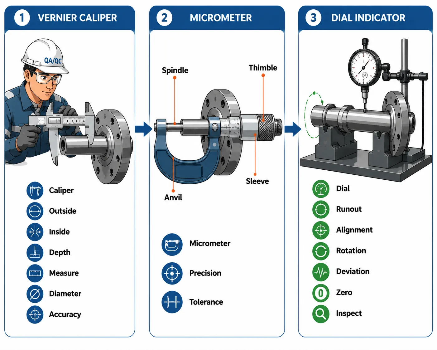
Mechanical engineers use numerous measuring instruments depending on inspection requirements. Each tool has specific applications and accuracy levels.
| Measurement Tool | Primary Purpose | Typical Accuracy | Common Applications | Key Benefit |
|---|---|---|---|---|
| Vernier Caliper | External, internal and depth measurements | 0.02 mm | Shafts, pipes, flanges, machined parts | Versatile measurement |
| Digital Caliper | Electronic dimensional measurement | 0.01 mm | Precision machining inspections | Fast and easy reading |
| Outside Micrometer | External diameter measurement | 0.001 mm | Shafts, pins, rods | Extremely high accuracy |
| Inside Micrometer | Internal diameter measurement | 0.001 mm | Bores, cylinders | Precise internal inspection |
| Dial Indicator | Alignment and runout inspection | 0.01 mm | Rotating equipment | Detects small movement |
Demonstrating the Proper Use of Vernier Calipers
What is a Vernier Caliper?
A Vernier caliper is one of the most widely used precision measuring instruments in mechanical engineering. It measures external dimensions, internal dimensions, step dimensions, and depth with high accuracy.
Because of its versatility, it is commonly used during fabrication, machining, assembly, maintenance, and final quality inspections.
Main Parts of a Vernier Caliper
The principal components include:
- Main scale
- Vernier scale
- Outside jaws
- Inside jaws
- Depth rod
- Lock screw
- Thumb roller
- Beam
Each component contributes to accurate and repeatable measurements.
Applications of Vernier Calipers
QA/QC inspectors commonly use Vernier calipers for measuring:
- Shaft diameters
- Pipe outside diameters
- Pipe inside diameters
- Plate thickness
- Bolt diameters
- Nut dimensions
- Flange thickness
- Groove widths
- Keyway dimensions
- Hole diameters
- Component depths
- Mechanical clearances
Procedure for Using a Vernier Caliper
Step 1: Clean the Instrument
Before measurement:
- Remove dust.
- Wipe measuring jaws.
- Ensure smooth movement.
- Check for visible damage.
Step 2: Inspect Zero Reading
Close the jaws completely.
Verify that:
- Zero aligns correctly.
- No visible gap exists.
- Calibration status is valid.
Step 3: Position the Component
Place the workpiece between the measuring jaws.
Ensure:
- Full contact.
- Proper alignment.
- No tilting.
- Stable positioning.
Step 4: Apply Correct Measuring Force
Close the jaws gently until they contact the workpiece.
Avoid:
- Excessive pressure.
- Loose contact.
- Instrument twisting.
Step 5: Read the Measurement
Record:
- Main scale reading
- Vernier scale reading
- Final calculated measurement
Document the value immediately.
Common Mistakes When Using Vernier Calipers
Inspectors should avoid:
- Measuring dirty surfaces.
- Applying excessive force.
- Reading from an angle (parallax error).
- Using damaged jaws.
- Ignoring calibration labels.
- Measuring moving components.
- Recording incorrect units.
- Failing to repeat measurements.
Demonstrating the Proper Use of Micrometers
What is a Micrometer?
A micrometer is a high-precision measuring instrument designed to measure external or internal dimensions with greater accuracy than a Vernier caliper. It is commonly used when tolerances are extremely tight and dimensional precision is critical.
QA/QC Mechanical Engineers frequently use micrometers for inspecting precision-machined components, bearings, shafts, sleeves, bushings, and other mechanical parts where even a small dimensional variation can affect equipment performance.
Types of Micrometers
The most commonly used micrometers include:
- Outside micrometer
- Inside micrometer
- Depth micrometer
- Digital micrometer
- Tube micrometer
- Blade micrometer
Each type is designed for a specific measurement application while maintaining a very high level of accuracy.
Major Components of an Outside Micrometer
An outside micrometer consists of several precision-engineered parts, including:
- Frame
- Anvil
- Spindle
- Sleeve
- Thimble
- Ratchet stop
- Lock nut
Together, these components ensure controlled measuring pressure and accurate dimensional readings.
Applications of Micrometers
Micrometers are commonly used during QA/QC inspections to measure:
- Shaft diameters
- Bearing journals
- Precision pins
- Rod diameters
- Plate thickness
- Bushings
- Sleeves
- Valve stems
- Machined components
- Thin metal sheets
Their superior accuracy makes them essential for verifying critical dimensions that cannot be measured reliably with less precise instruments.
Demonstrating the Proper Use of Dial Indicators
What is a Dial Indicator?
A dial indicator is a precision measuring instrument used to detect very small amounts of linear movement, displacement, misalignment, runout, flatness, and concentricity. Unlike Vernier calipers and micrometers, which directly measure dimensions, a dial indicator measures the amount of deviation from a reference point. This makes it an essential tool for alignment inspections, machine setup, equipment installation, maintenance, and quality verification.
QA/QC Mechanical Engineers use dial indicators extensively during equipment assembly, rotating machinery inspections, shaft alignment, flange inspection, and final acceptance testing. Because modern mechanical systems often require tolerances measured in hundredths or thousandths of a millimetre, the dial indicator provides the precision needed to verify compliance with engineering specifications.
Major Components of a Dial Indicator
A standard dial indicator consists of the following components:
- Dial face
- Pointer (needle)
- Graduated scale
- Contact point
- Plunger
- Stem
- Locking screw
- Mounting lug
Each component contributes to precise and repeatable measurements.
Applications of Dial Indicators
Dial indicators are widely used for:
- Shaft alignment
- Runout inspection
- Flatness inspection
- Surface alignment
- Concentricity checks
- Parallelism verification
- Machine installation
- Equipment maintenance
- Bearing inspection
- Flange alignment
- Rotating equipment inspection
- Precision machine setup
Procedure for Using a Dial Indicator
Step 1: Verify Calibration
Before use:
- Check calibration label.
- Confirm calibration validity.
- Inspect for physical damage.
- Ensure smooth pointer movement.
Step 2: Mount the Indicator Securely
Attach the dial indicator to a magnetic stand or fixture.
Ensure:
- Rigid mounting
- Stable base
- No vibration
- Correct contact angle
Step 3: Set the Zero Position
Move the contact point against the workpiece.
Rotate the bezel until the pointer aligns with zero.
Verify that the pointer returns consistently to the zero position.
Step 4: Perform the Measurement
Rotate or move the workpiece slowly.
Observe the pointer movement.
Record:
- Maximum reading
- Minimum reading
- Total indicator reading (TIR)
Step 5: Compare with Specifications
Evaluate whether the measured deviation falls within the specified engineering tolerance.
Record the inspection result in the QA/QC documentation.
Calibration Requirements for Measurement Instruments
Importance of Calibration
Calibration ensures that measuring instruments provide accurate and reliable readings. Even high-quality instruments can lose accuracy due to frequent use, accidental impacts, improper storage, or environmental conditions. Regular calibration confirms that the instrument remains traceable to recognized national or international standards.
Without proper calibration, inspection results become unreliable, increasing the risk of accepting defective components or rejecting acceptable products.
Objectives of Calibration
Calibration helps organizations to:
- Maintain measurement accuracy.
- Verify instrument reliability.
- Ensure traceability.
- Comply with ISO 9001 requirements.
- Reduce inspection errors.
- Improve customer confidence.
- Support audit compliance.
- Prevent production defects.
- Enhance product quality.
- Maintain consistent measurements.
Calibration Best Practices
QA/QC personnel should always:
- Use calibrated instruments only.
- Check calibration labels before inspection.
- Store instruments properly.
- Protect measuring surfaces.
- Clean instruments before and after use.
- Avoid dropping instruments.
- Maintain calibration records.
- Remove damaged instruments from service immediately.
Quality Inspection Procedure Using Precision Measurement Tools
A systematic inspection process improves consistency and minimizes human error.
Step 1: Review Engineering Documentation
Inspectors should first examine:
- Engineering drawings
- Inspection Test Plans (ITPs)
- Material specifications
- Applicable standards
- Customer requirements
Step 2: Select the Correct Instrument
Choose the measuring tool based on:
- Required accuracy
- Component geometry
- Measurement range
- Tolerance requirements
- Inspection method
Step 3: Prepare the Workpiece
Before measuring:
- Clean surfaces.
- Remove oil and debris.
- Ensure component stability.
- Verify identification markings.
Step 4: Verify Instrument Condition
Inspect the instrument for:
- Calibration status
- Physical damage
- Smooth operation
- Zero accuracy
- Clean measuring surfaces
Step 5: Perform Measurements
Follow the manufacturer’s recommended measuring technique.
Repeat measurements at multiple locations where appropriate to confirm consistency.
Step 6: Record Results
Inspection reports should include:
- Component identification
- Drawing number
- Instrument used
- Calibration reference
- Measured values
- Tolerance limits
- Inspection result
- Inspector’s name
- Inspection date
Step 7: Evaluate Conformance
Compare recorded measurements with engineering tolerances.
Classify the component as:
- Accept
- Reject
- Repair
- Rework
- Hold for further inspection
Common Measurement Errors During Quality Inspection
Measurement errors can significantly affect inspection reliability. QA/QC Mechanical Engineers should understand these common sources of error and implement preventive measures.
Typical Errors
- Parallax error
- Excessive measuring force
- Dirty measuring surfaces
- Instrument wear
- Incorrect zero setting
- Temperature variation
- Misalignment of the instrument
- Worn contact points
- Incorrect reading technique
- Poor lighting conditions
Methods to Prevent Errors
- Clean both instrument and workpiece.
- Allow components to reach ambient temperature.
- Hold instruments correctly.
- Use the correct measuring force.
- Repeat measurements.
- Verify calibration before use.
- Store instruments in protective cases.
- Follow standard operating procedures.
- Use appropriate lighting.
- Maintain concentration during inspection.
Best Practices for Using Measurement Instruments
Professional QA/QC Mechanical Engineers consistently follow best practices to ensure inspection accuracy and repeatability.
Recommended Practices
- Handle instruments carefully.
- Never use measuring tools as workshop tools.
- Avoid measuring rotating components.
- Protect measuring faces from scratches.
- Clean instruments after every use.
- Store instruments in dry environments.
- Perform periodic calibration.
- Use certified reference standards.
- Record all inspection measurements accurately.
- Report abnormal findings immediately.
- Follow company quality procedures.
- Maintain complete inspection traceability.
Practical Example
A QA/QC Mechanical Engineer is assigned to inspect a batch of stainless-steel pump shafts before assembly.
The engineering drawing specifies:
- Shaft diameter: 60.00 ± 0.02 mm
- Maximum runout: 0.03 mm
The inspector follows a structured inspection process:
- Reviews the approved engineering drawing.
- Selects a calibrated outside micrometer to measure the shaft diameter.
- Cleans both the shaft and measuring instrument.
- Measures the shaft at three different positions to verify dimensional consistency.
- Records values of 60.00 mm, 60.01 mm, and 59.99 mm, confirming compliance with the specified tolerance.
- Mounts the shaft on V-blocks and uses a calibrated dial indicator to measure runout.
- Rotates the shaft slowly and records a Total Indicator Reading (TIR) of 0.02 mm, which is within the allowable limit.
- Documents all measurements, calibration references, and inspection outcomes in the quality inspection report.
The shaft successfully passes inspection and is approved for assembly, ensuring reliable equipment performance and compliance with project quality requirements.
Case Study: Precision Measurement During Gearbox Manufacturing
Background
A mechanical engineering company manufacturing industrial gearboxes experienced repeated failures during factory acceptance testing. Investigation revealed excessive vibration and premature bearing wear. The QA/QC department initiated a detailed dimensional inspection to identify the root cause.
Inspection Activities
The inspection team carried out the following activities:
- Reviewed engineering drawings and tolerance specifications.
- Verified calibration certificates for all measuring instruments.
- Measured shaft diameters using calibrated outside micrometers.
- Checked housing bore dimensions using inside micrometers.
- Inspected flange and mounting surfaces with Vernier calipers.
- Measured shaft runout using dial indicators.
- Recorded all inspection data in standardized quality inspection forms.
Findings
The inspection revealed that:
- Shaft diameters complied with specified tolerances.
- Housing bore dimensions were acceptable.
- Dial indicator measurements identified excessive shaft runout of 0.08 mm, exceeding the allowable limit of 0.03 mm.
- Investigation confirmed improper machining during the final grinding process.
Corrective Actions
The organization implemented several corrective measures:
- Re-machined the affected shafts.
- Improved grinding machine alignment.
- Introduced additional in-process inspections.
- Increased calibration frequency for measuring instruments.
- Updated operator training on precision measurement techniques.
- Revised inspection procedures to include mandatory runout verification.
Results
Following these improvements:
- Gearbox vibration was significantly reduced.
- Bearing failures were eliminated.
- Product acceptance rates increased.
- Customer complaints decreased.
- Rework costs were reduced.
- Overall manufacturing quality improved.
This case demonstrates how the proper use of precision measurement tools enables QA/QC Mechanical Engineers to identify hidden defects, prevent equipment failures, and support continuous quality improvement.
Key Benefits of Proper Measurement Tool Usage
Effective use of calipers, micrometers, and dial indicators provides numerous advantages:
- Improves dimensional accuracy.
- Ensures compliance with engineering drawings.
- Detects defects before assembly.
- Reduces manufacturing errors.
- Minimizes product rejection.
- Prevents costly rework.
- Enhances equipment reliability.
- Supports regulatory compliance.
- Improves customer satisfaction.
- Strengthens quality documentation.
- Increases inspection consistency.
- Promotes continuous improvement.
- Supports preventive quality management.
- Enhances workplace safety.
- Builds confidence in inspection outcomes.
Key Takeaways
- Precision measurement is a core responsibility of QA/QC Mechanical Engineers.
- Vernier calipers are versatile instruments for measuring external, internal, depth, and step dimensions.
- Micrometers provide superior accuracy for inspecting components with tight tolerances.
- Dial indicators are essential for measuring runout, alignment, flatness, and concentricity.
- Calibration ensures the reliability and traceability of measurement results.
- Following standardized inspection procedures improves consistency and reduces human error.
- Proper handling, maintenance, and storage of measuring instruments extend their service life and preserve accuracy.
- Accurate measurement contributes directly to product quality, operational reliability, customer satisfaction, and compliance with international engineering standards.
Conclusion
The correct use of precision measurement tools is fundamental to achieving excellence in mechanical quality assurance and quality control. Instruments such as Vernier calipers, micrometers, and dial indicators enable QA/QC Mechanical Engineers to verify dimensional accuracy, detect manufacturing deviations, and ensure that every component complies with engineering specifications and international quality standards. When combined with proper calibration, standardized inspection procedures, and professional measurement techniques, these instruments provide reliable data that supports informed quality decisions throughout the manufacturing and inspection process.
Ultimately, precision measurement is far more than simply obtaining numerical values it is a critical quality management practice that protects product integrity, enhances equipment performance, reduces defects, and supports continuous improvement. By mastering the proper use of measurement tools and maintaining disciplined inspection practices, QA/QC professionals play a vital role in delivering safe, reliable, and high-quality mechanical products that meet customer expectations and industry requirements.
3. Describe the Role of Inspection in Ensuring Compliance with Engineering Specifications and Standards
Inspection plays a fundamental role in mechanical engineering quality assurance (QA) and quality control (QC) by ensuring that materials, components, equipment, and completed systems comply with approved engineering specifications, technical requirements, and international standards. In every stage of mechanical engineering projects, from material procurement and manufacturing to installation, commissioning, and maintenance, inspection provides objective evidence that quality requirements have been achieved.
For a QA/QC Mechanical Engineer, inspection is not simply a process of finding defects after production. It is a proactive quality management activity used to verify that engineering work is performed correctly, identify potential risks, prevent failures, and ensure that products meet their intended performance requirements. Through systematic inspection procedures, engineers evaluate whether mechanical products satisfy dimensional requirements, material specifications, manufacturing standards, safety regulations, and customer expectations.
Mechanical industries such as oil and gas, petrochemical, power generation, automotive, aerospace, marine, and industrial manufacturing depend heavily on inspection systems to maintain reliability and operational safety. Components such as pressure vessels, pipelines, pumps, compressors, valves, and rotating equipment must meet strict quality criteria before being placed into service. Inspection ensures that these products conform to standards such as ISO 9001, ASME, ASTM, API, AWS, and other internationally recognized engineering codes.
A well-developed inspection process provides confidence that engineering specifications have been followed and that finished products are safe, reliable, and suitable for their intended applications. By applying effective inspection techniques, QA/QC professionals contribute directly to improved product quality, reduced failures, minimized production costs, and successful project delivery.
Understanding Inspection in Mechanical Engineering
Definition of Inspection
Inspection is a systematic examination, measurement, testing, or evaluation process used to determine whether materials, components, assemblies, and completed products comply with specified engineering requirements.
In mechanical engineering, inspection involves comparing actual conditions against predefined acceptance criteria established in:
- Engineering drawings.
- Technical specifications.
- Quality procedures.
- Industry standards.
- Inspection and Test Plans (ITPs).
- Customer requirements.
The main purpose of inspection is to provide evidence that a product satisfies all required quality, safety, and performance expectations.
Key Objectives of Inspection
The primary objectives of mechanical inspection include:
- Confirming compliance with engineering requirements.
- Verifying product dimensions and tolerances.
- Ensuring correct material selection.
- Detecting defects and deviations.
- Maintaining manufacturing consistency.
- Preventing equipment failures.
- Supporting regulatory compliance.
- Ensuring customer satisfaction.
- Improving production processes.
- Reducing rework and waste.
- Maintaining quality documentation.
- Supporting continuous improvement.
Understanding Engineering Specifications
Definition of Engineering Specifications
Engineering specifications are detailed technical requirements that define how a mechanical product, component, or system must be designed, manufactured, tested, and accepted.
Specifications provide measurable criteria that inspectors use to determine whether a product meets required quality levels.
Examples of Engineering Specification Requirements
Engineering specifications may include:
- Material grade requirements.
- Component dimensions.
- Manufacturing tolerances.
- Surface finish requirements.
- Welding procedures.
- Heat treatment requirements.
- Pressure ratings.
- Testing requirements.
- Inspection methods.
- Acceptance criteria.
- Documentation requirements.
Importance of Engineering Specifications
Engineering specifications are essential because they:
- Provide clear quality expectations.
- Ensure consistent manufacturing.
- Define acceptance requirements.
- Support inspection activities.
- Reduce technical misunderstandings.
- Improve product reliability.
- Assist in quality verification.
- Support contractual compliance.
Without clear specifications, inspectors cannot accurately determine whether a product meets required standards.
Understanding Engineering Standards
Definition of Engineering Standards
Engineering standards are established technical guidelines that define recommended practices, requirements, and procedures for designing, manufacturing, inspecting, testing, and maintaining engineering products.
Standards provide a common framework that ensures safety, reliability, and consistency across industries.
Common Mechanical Engineering Standards
QA/QC Mechanical Engineers commonly work with:
- ISO 9001 – Quality Management Systems.
- ASME Boiler and Pressure Vessel Codes.
- ASTM Material Standards.
- API Standards for oil and gas equipment.
- AWS Welding Standards.
- ISO 17025 Laboratory Testing Requirements.
- EN and DIN Engineering Standards.
Role of Standards in Inspection
Engineering standards help inspectors to:
- Select appropriate inspection methods.
- Define acceptable quality levels.
- Evaluate test results.
- Determine defect acceptance limits.
- Ensure safe operation.
- Maintain industry compliance.
Role of Inspection in Ensuring Compliance
Inspection acts as a verification system that confirms whether engineering activities comply with approved specifications and standards.
A QA/QC Mechanical Engineer uses inspection to ensure that every stage of production follows the required quality criteria.
Verification of Material Compliance
Before manufacturing begins, inspection confirms that materials meet project requirements.
Material inspection includes:
- Reviewing Material Test Certificates (MTCs).
- Checking material grades.
- Verifying heat numbers.
- Confirming chemical composition.
- Reviewing mechanical properties.
- Inspecting material condition.
This prevents incorrect materials from entering production.
Verification of Manufacturing Processes
Inspection ensures that manufacturing activities are performed according to approved procedures.
Examples include:
- Welding procedure verification.
- Machining process inspection.
- Heat treatment verification.
- Assembly inspection.
- Surface preparation checks.
Verification of Dimensional Accuracy
Mechanical components must meet specified dimensions to ensure proper assembly and operation.
Dimensional inspection verifies:
- Length.
- Diameter.
- Thickness.
- Alignment.
- Flatness.
- Tolerance limits.
- Geometrical accuracy.
Measurement tools commonly used include:
- Vernier calipers.
- Micrometers.
- Dial indicators.
- Coordinate Measuring Machines (CMM).
Verification Through Testing
Inspection also involves testing activities to confirm performance and reliability.
Examples include:
- Pressure testing.
- Leak testing.
- Functional testing.
- Performance testing.
- Non-Destructive Testing (NDT).
These tests provide evidence that products can operate safely under expected conditions.
Inspection Process for Ensuring Compliance
A structured inspection process allows QA/QC teams to consistently evaluate product quality.
Step 1: Review Engineering Documents
Before inspection begins, the inspector reviews:
- Engineering drawings.
- Project specifications.
- Applicable standards.
- Inspection procedures.
- Acceptance criteria.
- Client requirements.
This ensures that inspection activities are performed according to approved requirements.
Step 2: Prepare Inspection Plan
An Inspection and Test Plan (ITP) defines:
- Inspection stages.
- Required tests.
- Responsible personnel.
- Acceptance criteria.
- Hold points.
- Witness points.
- Documentation requirements.
Step 3: Perform Inspection Activities
Inspection activities may include:
- Visual examination.
- Dimensional measurement.
- Material verification.
- Welding inspection.
- NDT examination.
- Functional testing.
Step 4: Evaluate Results
Inspection findings are compared with specifications.
The inspector determines whether the product is:
- Accepted.
- Rejected.
- Requires correction.
- Requires further evaluation.
Step 5: Document Inspection Evidence
Inspection records include:
- Inspection reports.
- Test certificates.
- Measurement results.
- Photographs.
- Calibration records.
- Non-Conformance Reports (NCRs).
Comparison Between Engineering Specifications and Standards
| Aspect | Engineering Specifications | Engineering Standards |
|---|---|---|
| Definition | Project-specific technical requirements defining product characteristics and acceptance criteria. | Recognized technical guidelines defining industry requirements and best practices. |
| Main Purpose | Ensures a product meets customer and project expectations. | Ensures safety, consistency, and industry-wide quality control. |
| Source | Prepared by engineers, designers, clients, and project teams. | Developed by organizations such as ISO, ASME, ASTM, and API. |
| Application | Applied to a specific project or product. | Applied across multiple industries and projects. |
| Inspection Role | Provides detailed requirements for inspection activities. | Provides accepted methods and evaluation criteria. |
| Quality Benefit | Ensures customer-specific compliance. | Ensures standardized quality and reliability. |
Role of QA/QC Mechanical Engineer in Inspection Compliance
QA/QC Mechanical Engineers are responsible for ensuring that inspection activities effectively verify compliance.
Their responsibilities include:
- Reviewing technical specifications.
- Preparing inspection procedures.
- Selecting inspection methods.
- Conducting quality inspections.
- Reviewing inspection results.
- Identifying non-conformities.
- Coordinating corrective actions.
- Maintaining inspection records.
- Communicating quality findings.
- Supporting audits.
- Ensuring compliance with standards.
Practical Example
A manufacturing company is producing pressure piping systems for a petrochemical facility. The project specification requires compliance with ASME piping standards.
The QA/QC Mechanical Engineer performs several inspection activities:
- Reviews material certificates.
- Confirms pipe dimensions.
- Checks welding procedures.
- Performs weld visual inspection.
- Reviews NDT reports.
- Verifies pressure test results.
During inspection, a weld defect is identified through radiographic testing. The defect does not meet acceptance criteria defined by the applicable standard.
The engineer issues a Non-Conformance Report (NCR), identifies the cause, and ensures corrective welding and re-testing are completed.
After successful correction, the piping system meets all engineering specifications and receives final approval.
Case Study: Inspection Compliance During Pressure Vessel Fabrication
Background
A company was manufacturing pressure vessels for an industrial processing plant. Due to high-pressure operating conditions, the client required strict compliance with ASME standards and project specifications.
Inspection Activities
The QA/QC team implemented a complete inspection programme including:
- Material verification.
- Welding inspection.
- Dimensional checks.
- NDT examination.
- Pressure testing.
- Final documentation review.
Issue Identified
During final dimensional inspection, inspectors discovered that one nozzle position exceeded the specified tolerance.
Corrective Action
The company:
- Reviewed the fabrication process.
- Corrected nozzle positioning.
- Repeated dimensional inspection.
- Updated fabrication controls.
- Verified final compliance.
Outcome
The pressure vessel successfully passed all inspections and tests.
The project achieved:
- ASME compliance.
- Client approval.
- Improved manufacturing controls.
- Increased product reliability.
This case demonstrates that inspection ensures engineering specifications are achieved before products enter operational environments.
Key Benefits of Inspection in Ensuring Compliance
Effective inspection provides many advantages:
- Ensures compliance with engineering specifications.
- Improves product reliability.
- Prevents safety failures.
- Detects defects early.
- Reduces production costs.
- Minimizes rework.
- Improves customer confidence.
- Supports regulatory compliance.
- Maintains quality traceability.
- Enhances manufacturing consistency.
- Supports continuous improvement.
- Reduces operational risks.
Key Takeaways
- Inspection is a critical QA/QC activity that verifies compliance with engineering specifications and standards.
- Engineering specifications define product requirements, while standards provide accepted industry practices.
- Inspection confirms material quality, dimensional accuracy, manufacturing processes, and product performance.
- QA/QC Mechanical Engineers use inspection results to make quality decisions and prevent failures.
- Proper inspection documentation provides evidence of compliance and supports audits.
- Effective inspection improves safety, reliability, and customer satisfaction.
Conclusion
Inspection plays a vital role in ensuring that mechanical products and systems comply with engineering specifications, customer requirements, and international standards. Through systematic examination, measurement, testing, and documentation, QA/QC Mechanical Engineers verify that materials, components, and finished products achieve the required quality levels.
Inspection is not only a defect detection activity but also a preventive quality management approach that improves manufacturing processes, reduces risks, and ensures long-term equipment reliability. By applying effective inspection procedures and following recognized engineering standards, organizations can deliver safe, efficient, and high-quality mechanical products that meet global industry expectations.
4. Explain the Importance of Testing for Product Performance, Reliability, and Durability
Testing is a fundamental activity in mechanical engineering quality assurance (QA) and quality control (QC) that ensures products, components, and systems perform safely, reliably, and efficiently throughout their intended service life. Before mechanical products are delivered to customers or placed into operation, they must undergo a series of carefully planned tests to verify that they meet engineering specifications, performance requirements, and international quality standards.
From the perspective of a QA/QC Mechanical Engineer, testing provides measurable evidence that a product can withstand operational conditions such as mechanical loads, pressure, temperature variations, vibration, fatigue, and environmental stresses. While inspection confirms whether a product has been manufactured correctly, testing evaluates whether that product can perform its intended function effectively and consistently.
In industries such as oil and gas, power generation, automotive, aerospace, marine, construction, and manufacturing, product failures can result in safety risks, financial losses, production downtime, and reputational damage. Therefore, testing plays a critical role in preventing failures by identifying weaknesses before products are released for operational use.
Mechanical testing methods such as pressure testing, performance testing, fatigue testing, load testing, vibration testing, and functional testing allow engineers to evaluate product behaviour under realistic or simulated operating conditions. Through proper testing procedures, organizations can improve product quality, increase reliability, extend service life, and ensure compliance with standards such as ISO 9001, ASME, ASTM, API, and other industry requirements.
Understanding Testing in Mechanical Engineering
Definition of Testing
Testing is a controlled process of evaluating the performance, behaviour, strength, functionality, and durability of a mechanical component, product, or system under specified conditions.
The purpose of testing is to determine whether a product:
Performs according to design requirements.
Can withstand operational conditions.
Meets safety requirements.
Provides reliable service.
Complies with engineering standards.
Testing provides objective data that helps engineers make informed decisions regarding product acceptance, improvement, or rejection.
Testing is a controlled process of evaluating the performance, behaviour, strength, functionality, and durability of a mechanical component, product, or system under specified conditions.
The purpose of testing is to determine whether a product:
Performs according to design requirements.
Can withstand operational conditions.
Meets safety requirements.
Provides reliable service.
Complies with engineering standards.
Testing provides objective data that helps engineers make informed decisions regarding product acceptance, improvement, or rejection.
Importance of Testing in Quality Assurance and Quality Control
Testing is an essential part of the Quality Management System (QMS) because it verifies that products achieve the required level of performance before reaching customers.
Testing is an essential part of the Quality Management System (QMS) because it verifies that products achieve the required level of performance before reaching customers.
Why Testing is Important
Testing helps organizations to:
Verify product functionality.
Confirm design performance.
Detect hidden defects.
Evaluate mechanical strength.
Assess operational reliability.
Predict product lifespan.
Improve manufacturing processes.
Reduce failure risks.
Ensure customer satisfaction.
Support regulatory compliance.
Maintain product reputation.
Improve safety performance.
A product that passes inspection but fails during operation can create serious consequences. Testing provides additional assurance that the product is capable of performing under real working conditions.
Testing helps organizations to:
Verify product functionality.
Confirm design performance.
Detect hidden defects.
Evaluate mechanical strength.
Assess operational reliability.
Predict product lifespan.
Improve manufacturing processes.
Reduce failure risks.
Ensure customer satisfaction.
Support regulatory compliance.
Maintain product reputation.
Improve safety performance.
A product that passes inspection but fails during operation can create serious consequences. Testing provides additional assurance that the product is capable of performing under real working conditions.
Understanding Product Performance, Reliability, and Durability
Product Performance
Definition
Product performance refers to the ability of a mechanical product or system to achieve its intended operational functions according to design requirements.
Performance evaluation determines whether equipment delivers expected results under specific operating conditions.
Examples include:
Pump flow capacity.
Motor output power.
Compressor efficiency.
Valve response time.
Machine operating speed.
Product performance refers to the ability of a mechanical product or system to achieve its intended operational functions according to design requirements.
Performance evaluation determines whether equipment delivers expected results under specific operating conditions.
Examples include:
Pump flow capacity.
Motor output power.
Compressor efficiency.
Valve response time.
Machine operating speed.
Factors Affecting Product Performance
Product performance can be influenced by:
Material quality.
Manufacturing accuracy.
Assembly quality.
Operating conditions.
Design parameters.
Maintenance practices.
Environmental conditions.
Product performance can be influenced by:
Material quality.
Manufacturing accuracy.
Assembly quality.
Operating conditions.
Design parameters.
Maintenance practices.
Environmental conditions.
Reliability
Definition
Reliability is the ability of a mechanical product to perform its required function consistently over a specified period without failure.
A reliable product should:
Operate continuously.
Maintain expected performance.
Resist operational stresses.
Require minimal corrective maintenance.
Reliability is the ability of a mechanical product to perform its required function consistently over a specified period without failure.
A reliable product should:
Operate continuously.
Maintain expected performance.
Resist operational stresses.
Require minimal corrective maintenance.
Importance of Reliability Testing
Reliability testing helps engineers determine:
Failure probability.
Component life expectancy.
Maintenance requirements.
Operational stability.
Long-term performance.
Reliability testing helps engineers determine:
Failure probability.
Component life expectancy.
Maintenance requirements.
Operational stability.
Long-term performance.
Durability
Definition
Durability refers to the ability of a product to withstand wear, stress, environmental conditions, and repeated operation over an extended period.
Durability testing evaluates how products perform under:
Repeated loading.
Extreme temperatures.
Corrosive environments.
Continuous operation.
Mechanical stress.
Durability refers to the ability of a product to withstand wear, stress, environmental conditions, and repeated operation over an extended period.
Durability testing evaluates how products perform under:
Repeated loading.
Extreme temperatures.
Corrosive environments.
Continuous operation.
Mechanical stress.
Types of Testing Used in Mechanical Engineering
Different testing methods are selected depending on product design, application, and performance requirements.
Different testing methods are selected depending on product design, application, and performance requirements.
Functional Testing
Definition
Functional testing verifies that a mechanical product operates according to its intended purpose.
It confirms whether all components work together correctly as a complete system.
Functional testing verifies that a mechanical product operates according to its intended purpose.
It confirms whether all components work together correctly as a complete system.
Applications
Functional testing is commonly performed on:
Pumps.
Compressors.
Motors.
Valves.
Hydraulic systems.
Pneumatic equipment.
Functional testing is commonly performed on:
Pumps.
Compressors.
Motors.
Valves.
Hydraulic systems.
Pneumatic equipment.
Parameters Evaluated
Engineers measure:
Speed.
Pressure.
Flow rate.
Temperature.
Vibration.
Power consumption.
Efficiency.
Engineers measure:
Speed.
Pressure.
Flow rate.
Temperature.
Vibration.
Power consumption.
Efficiency.
Performance Testing
Definition
Performance testing evaluates whether a product achieves specified operational outputs.
It determines whether equipment meets design expectations under controlled conditions.
Performance testing evaluates whether a product achieves specified operational outputs.
It determines whether equipment meets design expectations under controlled conditions.
Examples
Performance testing includes:
Pump capacity testing.
Engine output testing.
Heat exchanger efficiency testing.
Compressor performance evaluation.
Performance testing includes:
Pump capacity testing.
Engine output testing.
Heat exchanger efficiency testing.
Compressor performance evaluation.
Benefits
Performance testing helps to:
Verify design capability.
Identify operational limitations.
Improve efficiency.
Confirm customer requirements.
Performance testing helps to:
Verify design capability.
Identify operational limitations.
Improve efficiency.
Confirm customer requirements.
Pressure Testing
Definition
Pressure testing verifies the strength, integrity, and leak resistance of pressure-containing equipment.
It is widely used in industries where safety is critical.
Pressure testing verifies the strength, integrity, and leak resistance of pressure-containing equipment.
It is widely used in industries where safety is critical.
Applications
Pressure testing is performed on:
Pipelines.
Pressure vessels.
Boilers.
Hydraulic systems.
Storage tanks.
Pressure testing is performed on:
Pipelines.
Pressure vessels.
Boilers.
Hydraulic systems.
Storage tanks.
Common Methods
Hydrostatic testing.
Pneumatic testing.
Hydrostatic testing.
Pneumatic testing.
Defects Identified
Pressure testing can detect:
Leakage.
Weak joints.
Structural failures.
Material weaknesses.
Pressure testing can detect:
Leakage.
Weak joints.
Structural failures.
Material weaknesses.
Fatigue Testing
Definition
Fatigue testing evaluates how materials and components behave under repeated loading conditions over time.
Many mechanical components experience continuous cycles of stress during operation.
Fatigue testing evaluates how materials and components behave under repeated loading conditions over time.
Many mechanical components experience continuous cycles of stress during operation.
Applications
Fatigue testing is important for:
Shafts.
Springs.
Aircraft components.
Rotating machinery.
Structural parts.
Fatigue testing is important for:
Shafts.
Springs.
Aircraft components.
Rotating machinery.
Structural parts.
Purpose
It helps determine:
Fatigue life.
Crack development.
Failure resistance.
Long-term durability.
It helps determine:
Fatigue life.
Crack development.
Failure resistance.
Long-term durability.
Vibration Testing
Definition
Vibration testing evaluates how equipment responds to mechanical vibrations during operation.
Vibration testing evaluates how equipment responds to mechanical vibrations during operation.
Importance
It helps identify:
Alignment problems.
Bearing issues.
Imbalance.
Structural weaknesses.
Mechanical instability.
It helps identify:
Alignment problems.
Bearing issues.
Imbalance.
Structural weaknesses.
Mechanical instability.
Comparison of Mechanical Testing Methods
Testing Method Definition Main Purpose Common Applications Quality Benefit Functional Testing Evaluates whether equipment performs its intended operation. Verify system operation and functionality. Pumps, motors, valves, machinery. Confirms operational readiness. Performance Testing Measures product output against design requirements. Verify efficiency and capability. Engines, compressors, heat exchangers. Ensures expected performance. Pressure Testing Tests strength and leak resistance under pressure conditions. Verify structural integrity. Pipelines, vessels, boilers. Prevents pressure-related failures. Fatigue Testing Evaluates resistance to repeated loading cycles. Determine service life. Shafts, springs, structural parts. Improves durability prediction. Vibration Testing Measures response to mechanical vibrations. Identify dynamic weaknesses. Rotating equipment and machinery. Reduces operational failures.
| Testing Method | Definition | Main Purpose | Common Applications | Quality Benefit |
|---|---|---|---|---|
| Functional Testing | Evaluates whether equipment performs its intended operation. | Verify system operation and functionality. | Pumps, motors, valves, machinery. | Confirms operational readiness. |
| Performance Testing | Measures product output against design requirements. | Verify efficiency and capability. | Engines, compressors, heat exchangers. | Ensures expected performance. |
| Pressure Testing | Tests strength and leak resistance under pressure conditions. | Verify structural integrity. | Pipelines, vessels, boilers. | Prevents pressure-related failures. |
| Fatigue Testing | Evaluates resistance to repeated loading cycles. | Determine service life. | Shafts, springs, structural parts. | Improves durability prediction. |
| Vibration Testing | Measures response to mechanical vibrations. | Identify dynamic weaknesses. | Rotating equipment and machinery. | Reduces operational failures. |
Testing Process and Procedure
A structured testing process ensures accurate and reliable results.
A structured testing process ensures accurate and reliable results.
Step 1: Review Testing Requirements
Before testing begins, engineers review:
Engineering drawings.
Product specifications.
Testing procedures.
Applicable standards.
Acceptance criteria.
Before testing begins, engineers review:
Engineering drawings.
Product specifications.
Testing procedures.
Applicable standards.
Acceptance criteria.
Step 2: Prepare Testing Equipment
Testing equipment must be:
Calibrated.
Suitable for the application.
Properly maintained.
Verified before use.
Examples:
Pressure gauges.
Data acquisition systems.
Temperature sensors.
Vibration meters.
Testing equipment must be:
Calibrated.
Suitable for the application.
Properly maintained.
Verified before use.
Examples:
Pressure gauges.
Data acquisition systems.
Temperature sensors.
Vibration meters.
Step 3: Conduct Testing Activities
During testing:
Operate equipment according to procedures.
Monitor performance parameters.
Record measurements.
Observe abnormal conditions.
Maintain safety controls.
During testing:
Operate equipment according to procedures.
Monitor performance parameters.
Record measurements.
Observe abnormal conditions.
Maintain safety controls.
Step 4: Analyse Test Results
Engineers compare results against:
Design requirements.
Acceptance criteria.
Industry standards.
Results are classified as:
Accepted.
Rejected.
Requires corrective action.
Engineers compare results against:
Design requirements.
Acceptance criteria.
Industry standards.
Results are classified as:
Accepted.
Rejected.
Requires corrective action.
Step 5: Prepare Test Documentation
Testing records include:
Test reports.
Equipment details.
Measurement data.
Calibration certificates.
Acceptance approval.
Testing records include:
Test reports.
Equipment details.
Measurement data.
Calibration certificates.
Acceptance approval.
Role of QA/QC Mechanical Engineer in Testing
QA/QC Mechanical Engineers ensure that testing activities provide reliable evidence of product quality.
Their responsibilities include:
Preparing testing procedures.
Reviewing specifications.
Selecting suitable test methods.
Verifying equipment calibration.
Monitoring testing activities.
Reviewing test results.
Identifying failures.
Preparing reports.
Coordinating corrective actions.
Ensuring compliance with standards.
QA/QC Mechanical Engineers ensure that testing activities provide reliable evidence of product quality.
Their responsibilities include:
Preparing testing procedures.
Reviewing specifications.
Selecting suitable test methods.
Verifying equipment calibration.
Monitoring testing activities.
Reviewing test results.
Identifying failures.
Preparing reports.
Coordinating corrective actions.
Ensuring compliance with standards.
Practical Example
A manufacturer produces industrial centrifugal pumps for a water treatment facility. Before delivery, each pump undergoes extensive testing.
The QA/QC Mechanical Engineer performs:
Visual inspection.
Dimensional verification.
Functional testing.
Performance testing.
During performance testing, engineers measure:
Flow rate.
Pressure output.
Motor speed.
Vibration levels.
The results are compared with manufacturer specifications. The pump achieves the required flow capacity and operates within acceptable vibration limits.
The product is approved because testing confirms that it can perform reliably under operational conditions.
A manufacturer produces industrial centrifugal pumps for a water treatment facility. Before delivery, each pump undergoes extensive testing.
The QA/QC Mechanical Engineer performs:
Visual inspection.
Dimensional verification.
Functional testing.
Performance testing.
During performance testing, engineers measure:
Flow rate.
Pressure output.
Motor speed.
Vibration levels.
The results are compared with manufacturer specifications. The pump achieves the required flow capacity and operates within acceptable vibration limits.
The product is approved because testing confirms that it can perform reliably under operational conditions.
Case Study: Durability Testing of Industrial Gearbox
Background
A manufacturing company produced industrial gearboxes for heavy machinery applications. Previous customers reported premature failures caused by excessive wear and overheating.
The company introduced additional durability testing to improve product reliability.
A manufacturing company produced industrial gearboxes for heavy machinery applications. Previous customers reported premature failures caused by excessive wear and overheating.
The company introduced additional durability testing to improve product reliability.
Testing Activities
The QA/QC team performed:
Load testing.
Vibration testing.
Temperature monitoring.
Long-duration operational testing.
The QA/QC team performed:
Load testing.
Vibration testing.
Temperature monitoring.
Long-duration operational testing.
Results
Testing identified:
Excessive bearing temperature.
Increased vibration levels.
Early signs of component wear.
Testing identified:
Excessive bearing temperature.
Increased vibration levels.
Early signs of component wear.
Corrective Actions
The company:
Improved lubrication systems.
Modified bearing specifications.
Improved manufacturing tolerances.
Enhanced quality inspections.
The company:
Improved lubrication systems.
Modified bearing specifications.
Improved manufacturing tolerances.
Enhanced quality inspections.
Outcome
After improvements:
Gearbox reliability increased.
Failure rates decreased.
Customer satisfaction improved.
Equipment service life increased.
This case demonstrates how testing helps organizations identify weaknesses, improve product design, and enhance long-term durability.
After improvements:
Gearbox reliability increased.
Failure rates decreased.
Customer satisfaction improved.
Equipment service life increased.
This case demonstrates how testing helps organizations identify weaknesses, improve product design, and enhance long-term durability.
Key Benefits of Product Testing
Effective testing provides significant advantages:
Improves product performance.
Increases reliability.
Extends service life.
Prevents unexpected failures.
Enhances operational safety.
Reduces maintenance costs.
Supports quality certification.
Improves customer confidence.
Identifies design weaknesses.
Supports continuous improvement.
Reduces warranty claims.
Improves manufacturing processes.
Effective testing provides significant advantages:
Improves product performance.
Increases reliability.
Extends service life.
Prevents unexpected failures.
Enhances operational safety.
Reduces maintenance costs.
Supports quality certification.
Improves customer confidence.
Identifies design weaknesses.
Supports continuous improvement.
Reduces warranty claims.
Improves manufacturing processes.
Key Takeaways
Testing verifies whether mechanical products perform according to design requirements.
Performance testing confirms operational capability.
Reliability testing evaluates consistent operation over time.
Durability testing measures resistance to wear and long-term stresses.
QA/QC Mechanical Engineers use testing results to make quality decisions.
Proper testing reduces failures, improves safety, and increases customer confidence.
Testing is an essential requirement for achieving mechanical product quality and compliance.
Testing verifies whether mechanical products perform according to design requirements.
Performance testing confirms operational capability.
Reliability testing evaluates consistent operation over time.
Durability testing measures resistance to wear and long-term stresses.
QA/QC Mechanical Engineers use testing results to make quality decisions.
Proper testing reduces failures, improves safety, and increases customer confidence.
Testing is an essential requirement for achieving mechanical product quality and compliance.
Conclusion
Testing is a critical component of mechanical engineering quality control because it verifies product performance, reliability, and durability before products enter operational environments. Through controlled testing methods, engineers can evaluate whether components and systems can withstand real-world conditions while maintaining safety and efficiency.
For QA/QC Mechanical Engineers, testing provides valuable evidence that products meet engineering specifications, customer expectations, and international standards. By applying appropriate testing techniques, analysing results accurately, and implementing improvements, organizations can reduce failures, enhance product quality, and deliver reliable mechanical solutions with long-term operational value.
Testing is a critical component of mechanical engineering quality control because it verifies product performance, reliability, and durability before products enter operational environments. Through controlled testing methods, engineers can evaluate whether components and systems can withstand real-world conditions while maintaining safety and efficiency.
For QA/QC Mechanical Engineers, testing provides valuable evidence that products meet engineering specifications, customer expectations, and international standards. By applying appropriate testing techniques, analysing results accurately, and implementing improvements, organizations can reduce failures, enhance product quality, and deliver reliable mechanical solutions with long-term operational value.
5. Analyze Inspection and Test Results to Determine Conformity to Mechanical Product Standards and Specifications
Inspection and test result analysis is a critical responsibility within mechanical engineering quality assurance (QA) and quality control (QC). After completing inspections and testing activities, QA/QC Mechanical Engineers must carefully evaluate the collected data to determine whether mechanical products, components, and systems comply with approved engineering specifications, customer requirements, and international standards. The analysis process transforms raw inspection measurements and test results into meaningful quality decisions that determine whether a product can be accepted, repaired, reworked, or rejected.
In mechanical engineering industries, achieving product conformity is essential for ensuring safety, reliability, performance, and long-term operational efficiency. Components such as pressure vessels, pipelines, rotating equipment, machined parts, valves, pumps, and structural assemblies must satisfy strict dimensional, material, functional, and performance requirements before being released for service. By analysing inspection and test results systematically, engineers can identify deviations, investigate causes, implement corrective actions, and ensure that only compliant products proceed to the next stage.
A professional QA/QC Mechanical Engineer does not simply review measurement values or test reports; they interpret results against defined acceptance criteria, engineering drawings, specifications, and applicable standards such as ISO 9001, ASME, ASTM, API, AWS, and other industry-specific requirements. Effective analysis ensures traceability, supports continuous improvement, reduces failures, and strengthens confidence in mechanical product quality.
Inspection and test result analysis is a critical responsibility within mechanical engineering quality assurance (QA) and quality control (QC). After completing inspections and testing activities, QA/QC Mechanical Engineers must carefully evaluate the collected data to determine whether mechanical products, components, and systems comply with approved engineering specifications, customer requirements, and international standards. The analysis process transforms raw inspection measurements and test results into meaningful quality decisions that determine whether a product can be accepted, repaired, reworked, or rejected.
In mechanical engineering industries, achieving product conformity is essential for ensuring safety, reliability, performance, and long-term operational efficiency. Components such as pressure vessels, pipelines, rotating equipment, machined parts, valves, pumps, and structural assemblies must satisfy strict dimensional, material, functional, and performance requirements before being released for service. By analysing inspection and test results systematically, engineers can identify deviations, investigate causes, implement corrective actions, and ensure that only compliant products proceed to the next stage.
A professional QA/QC Mechanical Engineer does not simply review measurement values or test reports; they interpret results against defined acceptance criteria, engineering drawings, specifications, and applicable standards such as ISO 9001, ASME, ASTM, API, AWS, and other industry-specific requirements. Effective analysis ensures traceability, supports continuous improvement, reduces failures, and strengthens confidence in mechanical product quality.
Understanding Inspection and Test Result Analysis
Definition of Inspection and Test Result Analysis
Inspection and test result analysis is the systematic process of reviewing, interpreting, and evaluating inspection data and testing outcomes to determine whether a mechanical product conforms to specified quality requirements.
The analysis involves comparing actual results with:
- Engineering drawings
- Technical specifications
- Design requirements
- Tolerance limits
- Industry standards
- Inspection and Test Plans (ITPs)
- Customer acceptance criteria
The final objective is to make an evidence-based quality decision.
Inspection and test result analysis is the systematic process of reviewing, interpreting, and evaluating inspection data and testing outcomes to determine whether a mechanical product conforms to specified quality requirements.
The analysis involves comparing actual results with:
- Engineering drawings
- Technical specifications
- Design requirements
- Tolerance limits
- Industry standards
- Inspection and Test Plans (ITPs)
- Customer acceptance criteria
The final objective is to make an evidence-based quality decision.
Purpose of Result Analysis
The main purpose of analysing inspection and test results is to:
- Confirm product conformity.
- Identify defects and deviations.
- Verify compliance with standards.
- Prevent defective products from reaching customers.
- Support quality improvement.
- Reduce manufacturing risks.
- Ensure operational reliability.
- Maintain customer satisfaction.
- Provide documented quality evidence.
The main purpose of analysing inspection and test results is to:
- Confirm product conformity.
- Identify defects and deviations.
- Verify compliance with standards.
- Prevent defective products from reaching customers.
- Support quality improvement.
- Reduce manufacturing risks.
- Ensure operational reliability.
- Maintain customer satisfaction.
- Provide documented quality evidence.
Importance of Conformity Assessment in Mechanical Engineering
Definition of Conformity
Conformity means that a mechanical product, component, or system meets all specified requirements defined by engineering documents, quality standards, and customer expectations.
A product is considered conforming when:
- Dimensions are within allowable tolerances.
- Materials meet specified requirements.
- Manufacturing processes follow approved procedures.
- Testing results satisfy acceptance criteria.
- Performance meets design expectations.
Conformity means that a mechanical product, component, or system meets all specified requirements defined by engineering documents, quality standards, and customer expectations.
A product is considered conforming when:
- Dimensions are within allowable tolerances.
- Materials meet specified requirements.
- Manufacturing processes follow approved procedures.
- Testing results satisfy acceptance criteria.
- Performance meets design expectations.
Why Conformity Analysis is Important
Mechanical products often operate under extreme conditions involving:
- High pressure
- High temperature
- Mechanical loads
- Vibration
- Corrosive environments
- Continuous operation
Failure of a non-conforming component can result in:
- Equipment breakdown.
- Production losses.
- Safety incidents.
- Environmental damage.
- Expensive repairs.
- Contractual disputes.
Therefore, accurate analysis of inspection and test results is essential for maintaining engineering reliability.
Mechanical products often operate under extreme conditions involving:
- High pressure
- High temperature
- Mechanical loads
- Vibration
- Corrosive environments
- Continuous operation
Failure of a non-conforming component can result in:
- Equipment breakdown.
- Production losses.
- Safety incidents.
- Environmental damage.
- Expensive repairs.
- Contractual disputes.
Therefore, accurate analysis of inspection and test results is essential for maintaining engineering reliability.
Key Concepts in Inspection and Test Result Evaluation
Acceptance Criteria
Acceptance criteria define the limits or requirements that a product must satisfy to be approved.
Examples include:
- Dimensional tolerances.
- Maximum allowable defects.
- Pressure test limits.
- Weld acceptance requirements.
- Surface finish specifications.
Acceptance criteria define the limits or requirements that a product must satisfy to be approved.
Examples include:
- Dimensional tolerances.
- Maximum allowable defects.
- Pressure test limits.
- Weld acceptance requirements.
- Surface finish specifications.
Tolerance Evaluation
Tolerance evaluation determines whether measured values fall within the acceptable range specified in engineering drawings.
Example:
Specified shaft diameter:
50.00 mm ± 0.05 mm
Acceptable range:
- Minimum: 49.95 mm
- Maximum: 50.05 mm
If inspection results show:
- 50.02 mm → Acceptable
- 50.08 mm → Non-conforming
Tolerance evaluation determines whether measured values fall within the acceptable range specified in engineering drawings.
Example:
Specified shaft diameter:
50.00 mm ± 0.05 mm
Acceptable range:
- Minimum: 49.95 mm
- Maximum: 50.05 mm
If inspection results show:
- 50.02 mm → Acceptable
- 50.08 mm → Non-conforming
Deviation Analysis
Deviation analysis identifies differences between actual results and required specifications.
Common deviations include:
- Incorrect dimensions.
- Material mismatch.
- Excessive vibration.
- Leakage.
- Improper alignment.
- Failed performance tests.
Deviation analysis identifies differences between actual results and required specifications.
Common deviations include:
- Incorrect dimensions.
- Material mismatch.
- Excessive vibration.
- Leakage.
- Improper alignment.
- Failed performance tests.
Traceability
Traceability ensures that inspection and test results can be linked back to:
- Specific components.
- Material batches.
- Manufacturing processes.
- Inspection personnel.
- Testing equipment.
- Calibration records.
Traceability ensures that inspection and test results can be linked back to:
- Specific components.
- Material batches.
- Manufacturing processes.
- Inspection personnel.
- Testing equipment.
- Calibration records.
Mechanical Product Standards and Specifications
QA/QC Mechanical Engineers evaluate inspection results against recognised standards and project requirements.
Common references include:
Standard / Specification Purpose Inspection Application Quality Benefit ISO 9001 Quality Management System requirements Quality procedures and documentation Ensures controlled quality processes ASME Codes Mechanical design and fabrication requirements Pressure equipment, piping, vessels Improves safety and reliability ASTM Standards Material and testing requirements Material verification and mechanical testing Ensures material conformity API Standards Oil and gas equipment requirements Pipelines, valves, rotating equipment Supports industrial reliability AWS Standards Welding quality requirements Weld inspection and acceptance Improves fabrication quality
QA/QC Mechanical Engineers evaluate inspection results against recognised standards and project requirements.
Common references include:
| Standard / Specification | Purpose | Inspection Application | Quality Benefit |
|---|---|---|---|
| ISO 9001 | Quality Management System requirements | Quality procedures and documentation | Ensures controlled quality processes |
| ASME Codes | Mechanical design and fabrication requirements | Pressure equipment, piping, vessels | Improves safety and reliability |
| ASTM Standards | Material and testing requirements | Material verification and mechanical testing | Ensures material conformity |
| API Standards | Oil and gas equipment requirements | Pipelines, valves, rotating equipment | Supports industrial reliability |
| AWS Standards | Welding quality requirements | Weld inspection and acceptance | Improves fabrication quality |
Process for Analysing Inspection and Test Results
Step 1: Collect Inspection Data
The first stage involves gathering all relevant inspection and testing information.
Data sources include:
- Visual inspection reports.
- Dimensional inspection records.
- Material certificates.
- NDT reports.
- Pressure test results.
- Functional test reports.
- Calibration records.
- Manufacturing documentation.
The first stage involves gathering all relevant inspection and testing information.
Data sources include:
- Visual inspection reports.
- Dimensional inspection records.
- Material certificates.
- NDT reports.
- Pressure test results.
- Functional test reports.
- Calibration records.
- Manufacturing documentation.
Step 2: Review Applicable Requirements

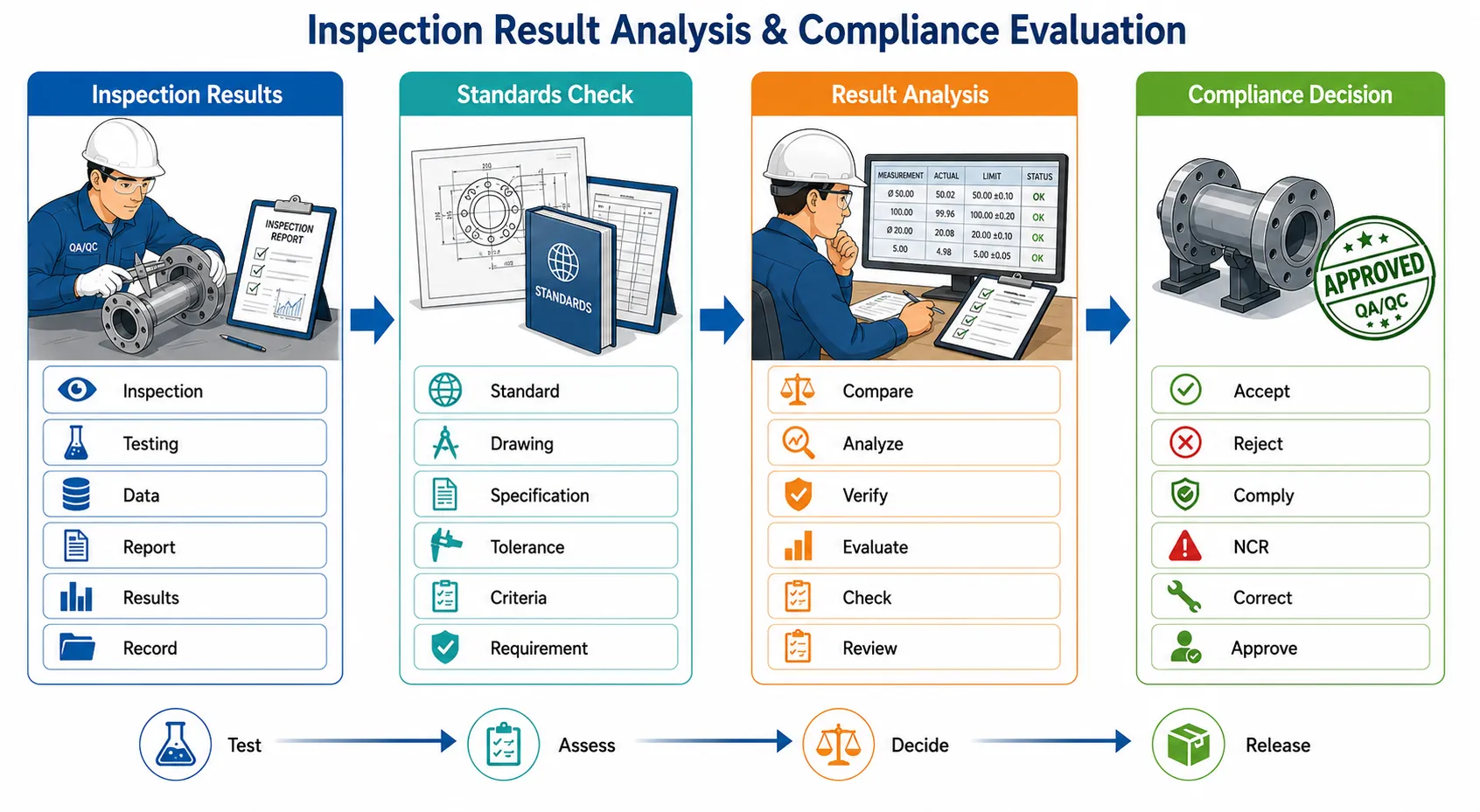
Before evaluating results, inspectors must identify the correct acceptance criteria.
Review includes:
- Engineering drawings.
- Project specifications.
- Client requirements.
- Applicable standards.
- Inspection procedures.
- Approved quality plans.
Before evaluating results, inspectors must identify the correct acceptance criteria.
Review includes:
- Engineering drawings.
- Project specifications.
- Client requirements.
- Applicable standards.
- Inspection procedures.
- Approved quality plans.
Step 3: Compare Results Against Specifications
Measured values and test outcomes are compared with required limits.
The engineer evaluates:
- Whether dimensions are within tolerance.
- Whether material properties meet requirements.
- Whether test pressures are acceptable.
- Whether performance meets design criteria.
Measured values and test outcomes are compared with required limits.
The engineer evaluates:
- Whether dimensions are within tolerance.
- Whether material properties meet requirements.
- Whether test pressures are acceptable.
- Whether performance meets design criteria.
Step 4: Classify Results
Inspection outcomes are normally classified as:
Inspection outcomes are normally classified as:
Accepted
The product meets all requirements.
The product meets all requirements.
Conditionally Accepted
Minor issues exist but can be accepted with approval or additional controls.
Minor issues exist but can be accepted with approval or additional controls.
Rejected
The product fails to meet specified requirements.
The product fails to meet specified requirements.
Methods Used to Analyse Inspection Results
Dimensional Analysis
Dimensional analysis involves reviewing measurements from instruments such as:
- Vernier calipers.
- Micrometers.
- Dial indicators.
- Coordinate Measuring Machines (CMM).
Engineers evaluate:
- Size accuracy.
- Alignment.
- Flatness.
- Roundness.
- Position accuracy.
- Surface dimensions.
Dimensional analysis involves reviewing measurements from instruments such as:
- Vernier calipers.
- Micrometers.
- Dial indicators.
- Coordinate Measuring Machines (CMM).
Engineers evaluate:
- Size accuracy.
- Alignment.
- Flatness.
- Roundness.
- Position accuracy.
- Surface dimensions.
Material Test Analysis
Material test results confirm whether materials meet specified mechanical properties.
Evaluation may include:
- Tensile strength.
- Yield strength.
- Hardness.
- Chemical composition.
- Impact resistance.
Material test results confirm whether materials meet specified mechanical properties.
Evaluation may include:
- Tensile strength.
- Yield strength.
- Hardness.
- Chemical composition.
- Impact resistance.
Non-Destructive Testing Analysis
NDT results are analysed to identify internal or surface defects without damaging components.
Methods include:
- Ultrasonic Testing (UT).
- Radiographic Testing (RT).
- Magnetic Particle Testing (MT).
- Dye Penetrant Testing (PT).
Engineers evaluate:
- Defect size.
- Defect location.
- Severity level.
- Acceptance limits.
NDT results are analysed to identify internal or surface defects without damaging components.
Methods include:
- Ultrasonic Testing (UT).
- Radiographic Testing (RT).
- Magnetic Particle Testing (MT).
- Dye Penetrant Testing (PT).
Engineers evaluate:
- Defect size.
- Defect location.
- Severity level.
- Acceptance limits.
Functional Test Analysis
Functional testing verifies whether equipment performs correctly under operating conditions.
Parameters analysed include:
- Pressure.
- Temperature.
- Flow rate.
- Speed.
- Vibration.
- Efficiency.
- Load performance.
Functional testing verifies whether equipment performs correctly under operating conditions.
Parameters analysed include:
- Pressure.
- Temperature.
- Flow rate.
- Speed.
- Vibration.
- Efficiency.
- Load performance.
Role of QA/QC Mechanical Engineer in Result Analysis
A QA/QC Mechanical Engineer plays a key role in ensuring accurate interpretation of inspection and test results.
Responsibilities include:
- Reviewing inspection reports.
- Verifying measurement accuracy.
- Comparing results with specifications.
- Identifying non-conformities.
- Preparing quality reports.
- Coordinating corrective actions.
- Communicating findings with stakeholders.
- Supporting client inspections.
- Maintaining quality documentation.
- Ensuring compliance with standards.
A QA/QC Mechanical Engineer plays a key role in ensuring accurate interpretation of inspection and test results.
Responsibilities include:
- Reviewing inspection reports.
- Verifying measurement accuracy.
- Comparing results with specifications.
- Identifying non-conformities.
- Preparing quality reports.
- Coordinating corrective actions.
- Communicating findings with stakeholders.
- Supporting client inspections.
- Maintaining quality documentation.
- Ensuring compliance with standards.
Practical Example
A manufacturing company produces industrial pump shafts for a chemical processing plant. The engineering specification requires:
- Shaft diameter: 75.00 ± 0.03 mm
- Maximum runout: 0.02 mm
- Surface finish: Specified machining quality
During inspection:
- Micrometer measurements confirm the shaft diameter is 75.01 mm.
- Dial indicator testing identifies runout of 0.015 mm.
- Visual inspection confirms no surface defects.
The QA/QC Mechanical Engineer compares these results against acceptance criteria and confirms that all requirements are satisfied.
The shaft is approved for assembly because inspection evidence demonstrates conformity with engineering specifications.
A manufacturing company produces industrial pump shafts for a chemical processing plant. The engineering specification requires:
- Shaft diameter: 75.00 ± 0.03 mm
- Maximum runout: 0.02 mm
- Surface finish: Specified machining quality
During inspection:
- Micrometer measurements confirm the shaft diameter is 75.01 mm.
- Dial indicator testing identifies runout of 0.015 mm.
- Visual inspection confirms no surface defects.
The QA/QC Mechanical Engineer compares these results against acceptance criteria and confirms that all requirements are satisfied.
The shaft is approved for assembly because inspection evidence demonstrates conformity with engineering specifications.
Case Study: Analysis of Test Results During Pressure Equipment Manufacturing
Background
A mechanical fabrication company manufactured pressure vessels for an industrial processing facility. Due to high operating pressure requirements, strict inspection and testing procedures were implemented.
A mechanical fabrication company manufactured pressure vessels for an industrial processing facility. Due to high operating pressure requirements, strict inspection and testing procedures were implemented.
Inspection and Testing Activities
The QA/QC team performed:
- Material verification.
- Welding inspections.
- Dimensional checks.
- Radiographic testing.
- Hydrostatic pressure testing.
- Final visual inspection.
The QA/QC team performed:
- Material verification.
- Welding inspections.
- Dimensional checks.
- Radiographic testing.
- Hydrostatic pressure testing.
- Final visual inspection.
Problem Identified
During hydrostatic testing, pressure loss was detected after maintaining the required test pressure.
The inspection team analysed:
- Pressure readings.
- Test duration.
- Leakage location.
- Weld inspection reports.
During hydrostatic testing, pressure loss was detected after maintaining the required test pressure.
The inspection team analysed:
- Pressure readings.
- Test duration.
- Leakage location.
- Weld inspection reports.
Root Cause
Further investigation identified a minor welding defect that caused leakage.
Further investigation identified a minor welding defect that caused leakage.
Corrective Action
The company:
- Repaired the weld area.
- Repeated NDT inspection.
- Conducted another pressure test.
- Updated welding monitoring procedures.
The company:
- Repaired the weld area.
- Repeated NDT inspection.
- Conducted another pressure test.
- Updated welding monitoring procedures.
Final Outcome
After corrective action:
- Test results met acceptance criteria.
- The vessel complied with ASME requirements.
- Client approval was achieved.
- Product reliability was improved.
This case demonstrates how effective analysis of inspection and test results helps identify problems, implement solutions, and ensure mechanical products meet required standards.
After corrective action:
- Test results met acceptance criteria.
- The vessel complied with ASME requirements.
- Client approval was achieved.
- Product reliability was improved.
This case demonstrates how effective analysis of inspection and test results helps identify problems, implement solutions, and ensure mechanical products meet required standards.
Key Benefits of Inspection and Test Result Analysis
Effective analysis provides significant advantages:
- Ensures compliance with engineering standards.
- Improves product reliability.
- Prevents equipment failures.
- Reduces manufacturing risks.
- Supports informed quality decisions.
- Minimizes rework and rejection costs.
- Improves customer satisfaction.
- Strengthens quality documentation.
- Supports regulatory compliance.
- Enhances continuous improvement.
- Improves operational safety.
- Provides evidence-based acceptance decisions.
Effective analysis provides significant advantages:
- Ensures compliance with engineering standards.
- Improves product reliability.
- Prevents equipment failures.
- Reduces manufacturing risks.
- Supports informed quality decisions.
- Minimizes rework and rejection costs.
- Improves customer satisfaction.
- Strengthens quality documentation.
- Supports regulatory compliance.
- Enhances continuous improvement.
- Improves operational safety.
- Provides evidence-based acceptance decisions.
Key Takeaways
- Inspection and test result analysis is essential for confirming mechanical product conformity.
- QA/QC Engineers evaluate results against drawings, specifications, and international standards.
- Acceptance criteria determine whether products are approved or rejected.
- Accurate analysis prevents defective products from reaching service environments.
- Documentation and traceability are critical elements of quality verification.
- Effective result analysis supports safety, reliability, and continuous improvement.
- Inspection and test result analysis is essential for confirming mechanical product conformity.
- QA/QC Engineers evaluate results against drawings, specifications, and international standards.
- Acceptance criteria determine whether products are approved or rejected.
- Accurate analysis prevents defective products from reaching service environments.
- Documentation and traceability are critical elements of quality verification.
- Effective result analysis supports safety, reliability, and continuous improvement.
Conclusion
Analysing inspection and test results is a fundamental responsibility in mechanical engineering quality control. It enables QA/QC Mechanical Engineers to determine whether products comply with engineering specifications, customer requirements, and international standards. Through systematic evaluation of dimensional measurements, material tests, non-destructive testing results, and functional performance data, engineers can make accurate quality decisions that protect product integrity and operational safety.
A strong inspection analysis process does not only identify failures; it provides opportunities for improvement by highlighting process weaknesses, preventing repeated defects, and enhancing manufacturing performance. By applying professional evaluation methods, maintaining accurate documentation, and following recognised engineering standards, QA/QC professionals ensure that mechanical products are safe, reliable, compliant, and suitable for their intended applications.
Analysing inspection and test results is a fundamental responsibility in mechanical engineering quality control. It enables QA/QC Mechanical Engineers to determine whether products comply with engineering specifications, customer requirements, and international standards. Through systematic evaluation of dimensional measurements, material tests, non-destructive testing results, and functional performance data, engineers can make accurate quality decisions that protect product integrity and operational safety.
A strong inspection analysis process does not only identify failures; it provides opportunities for improvement by highlighting process weaknesses, preventing repeated defects, and enhancing manufacturing performance. By applying professional evaluation methods, maintaining accurate documentation, and following recognised engineering standards, QA/QC professionals ensure that mechanical products are safe, reliable, compliant, and suitable for their intended applications.
6. Apply Inspection and Testing Techniques to Detect Defects, Non-Conformities, and Process Variations
Inspection and testing techniques are essential elements of mechanical engineering quality assurance (QA) and quality control (QC) systems. In modern manufacturing, fabrication, installation, and maintenance environments, ensuring product reliability requires more than producing components according to design drawings. Mechanical products must be continuously inspected and tested to identify defects, detect non-conformities, control process variations, and verify compliance with engineering specifications and international standards.
From the perspective of a QA/QC Mechanical Engineer, inspection is a proactive activity used to prevent failures rather than simply identify problems after production is completed. Through systematic inspection and testing, engineers can evaluate material quality, dimensional accuracy, manufacturing processes, assembly conditions, and operational performance. Early detection of defects allows organizations to implement corrective actions before products reach customers or enter service environments.
Mechanical industries such as oil and gas, petrochemical, power generation, automotive, aerospace, marine, and heavy manufacturing rely on advanced inspection methods including visual inspection, dimensional measurement, non-destructive testing (NDT), pressure testing, functional testing, and performance evaluation. These techniques provide objective evidence about product quality and help organizations maintain compliance with standards such as ISO 9001, ASME, ASTM, API, AWS, and other industry-specific requirements.
Applying inspection and testing techniques effectively enables engineers to identify manufacturing errors, investigate root causes, reduce waste, improve production efficiency, and ensure that mechanical products achieve their intended performance, safety, and service life.
Inspection and testing techniques are essential elements of mechanical engineering quality assurance (QA) and quality control (QC) systems. In modern manufacturing, fabrication, installation, and maintenance environments, ensuring product reliability requires more than producing components according to design drawings. Mechanical products must be continuously inspected and tested to identify defects, detect non-conformities, control process variations, and verify compliance with engineering specifications and international standards.
From the perspective of a QA/QC Mechanical Engineer, inspection is a proactive activity used to prevent failures rather than simply identify problems after production is completed. Through systematic inspection and testing, engineers can evaluate material quality, dimensional accuracy, manufacturing processes, assembly conditions, and operational performance. Early detection of defects allows organizations to implement corrective actions before products reach customers or enter service environments.
Mechanical industries such as oil and gas, petrochemical, power generation, automotive, aerospace, marine, and heavy manufacturing rely on advanced inspection methods including visual inspection, dimensional measurement, non-destructive testing (NDT), pressure testing, functional testing, and performance evaluation. These techniques provide objective evidence about product quality and help organizations maintain compliance with standards such as ISO 9001, ASME, ASTM, API, AWS, and other industry-specific requirements.
Applying inspection and testing techniques effectively enables engineers to identify manufacturing errors, investigate root causes, reduce waste, improve production efficiency, and ensure that mechanical products achieve their intended performance, safety, and service life.
Understanding Defects, Non-Conformities, and Process Variations
Definition of Defects
A defect is any condition, imperfection, or failure in a mechanical product that prevents it from meeting specified requirements or performing its intended function.
Defects may occur due to:
-
Incorrect material selection.
-
Manufacturing errors.
-
Poor workmanship.
-
Incorrect machining.
-
Welding problems.
-
Improper assembly.
-
Equipment malfunction.
-
Human error.
-
Environmental conditions.
A defect is any condition, imperfection, or failure in a mechanical product that prevents it from meeting specified requirements or performing its intended function.
Defects may occur due to:
- Incorrect material selection.
- Manufacturing errors.
- Poor workmanship.
- Incorrect machining.
- Welding problems.
- Improper assembly.
- Equipment malfunction.
- Human error.
- Environmental conditions.
Common Mechanical Defects
Examples of defects in mechanical engineering include:
-
Cracks.
-
Porosity.
-
Weld undercut.
-
Surface damage.
-
Corrosion.
-
Dimensional errors.
-
Misalignment.
-
Excessive vibration.
-
Leakage.
-
Poor surface finish.
-
Material weaknesses.
-
Incorrect tolerances.
Examples of defects in mechanical engineering include:
- Cracks.
- Porosity.
- Weld undercut.
- Surface damage.
- Corrosion.
- Dimensional errors.
- Misalignment.
- Excessive vibration.
- Leakage.
- Poor surface finish.
- Material weaknesses.
- Incorrect tolerances.
Definition of Non-Conformity
A non-conformity occurs when a product, process, or activity does not meet specified requirements defined by engineering drawings, customer specifications, procedures, or applicable standards.
A non-conforming condition does not always mean the product is unusable; however, it requires evaluation and corrective action.
Examples include:
-
A component dimension outside tolerance.
-
A failed pressure test.
-
Missing inspection documentation.
-
Incorrect material certification.
-
Welding outside acceptance criteria.
A non-conformity occurs when a product, process, or activity does not meet specified requirements defined by engineering drawings, customer specifications, procedures, or applicable standards.
A non-conforming condition does not always mean the product is unusable; however, it requires evaluation and corrective action.
Examples include:
- A component dimension outside tolerance.
- A failed pressure test.
- Missing inspection documentation.
- Incorrect material certification.
- Welding outside acceptance criteria.
Definition of Process Variation
Process variation refers to differences that occur during manufacturing or production activities that affect consistency and product quality.
Variation may result from:
-
Machine conditions.
-
Tool wear.
-
Operator differences.
-
Material changes.
-
Environmental factors.
-
Process instability.
Controlling process variation is essential because excessive variation increases defect rates and reduces manufacturing reliability.
Process variation refers to differences that occur during manufacturing or production activities that affect consistency and product quality.
Variation may result from:
- Machine conditions.
- Tool wear.
- Operator differences.
- Material changes.
- Environmental factors.
- Process instability.
Controlling process variation is essential because excessive variation increases defect rates and reduces manufacturing reliability.
Importance of Inspection and Testing for Defect Detection
Inspection and testing provide a structured method for identifying quality problems before they become serious operational issues.
Inspection and testing provide a structured method for identifying quality problems before they become serious operational issues.
Key Importance
Effective inspection and testing help organizations to:
-
Detect defects at an early stage.
-
Prevent defective products from reaching customers.
-
Maintain product reliability.
-
Improve manufacturing processes.
-
Reduce repair costs.
-
Minimize production delays.
-
Ensure compliance with standards.
-
Protect workplace safety.
-
Improve customer satisfaction.
-
Support continuous improvement.
Effective inspection and testing help organizations to:
- Detect defects at an early stage.
- Prevent defective products from reaching customers.
- Maintain product reliability.
- Improve manufacturing processes.
- Reduce repair costs.
- Minimize production delays.
- Ensure compliance with standards.
- Protect workplace safety.
- Improve customer satisfaction.
- Support continuous improvement.
Role of QA/QC Mechanical Engineers
QA/QC Mechanical Engineers are responsible for ensuring that inspection and testing activities are performed correctly and that defects are properly identified, documented, and resolved.
Their responsibilities include:
-
Reviewing engineering specifications.
-
Preparing inspection plans.
-
Selecting suitable inspection methods.
-
Performing quality inspections.
-
Evaluating test results.
-
Identifying non-conformities.
-
Preparing inspection reports.
-
Supporting root cause analysis.
-
Monitoring corrective actions.
-
Ensuring compliance with standards.
QA/QC Mechanical Engineers are responsible for ensuring that inspection and testing activities are performed correctly and that defects are properly identified, documented, and resolved.
Their responsibilities include:
- Reviewing engineering specifications.
- Preparing inspection plans.
- Selecting suitable inspection methods.
- Performing quality inspections.
- Evaluating test results.
- Identifying non-conformities.
- Preparing inspection reports.
- Supporting root cause analysis.
- Monitoring corrective actions.
- Ensuring compliance with standards.
Inspection Techniques Used for Detecting Defects
Different inspection methods are selected depending on the type of component, material, manufacturing process, and quality requirements.
Different inspection methods are selected depending on the type of component, material, manufacturing process, and quality requirements.
Visual Inspection
Definition
Visual inspection is the examination of mechanical components using direct observation or optical aids to identify visible defects and workmanship issues.
It is usually the first inspection method performed because it is simple, economical, and effective for detecting surface-level problems.
Visual inspection is the examination of mechanical components using direct observation or optical aids to identify visible defects and workmanship issues.
It is usually the first inspection method performed because it is simple, economical, and effective for detecting surface-level problems.
Applications of Visual Inspection
Visual inspection is commonly used for:
-
Weld inspection.
-
Surface examination.
-
Corrosion detection.
-
Assembly verification.
-
Coating inspection.
-
Fabrication monitoring.
Visual inspection is commonly used for:
- Weld inspection.
- Surface examination.
- Corrosion detection.
- Assembly verification.
- Coating inspection.
- Fabrication monitoring.
Defects Detected Through Visual Inspection
Inspectors can identify:
-
Surface cracks.
-
Welding imperfections.
-
Corrosion.
-
Deformation.
-
Scratches.
-
Poor finishing.
-
Incorrect assembly.
Inspectors can identify:
- Surface cracks.
- Welding imperfections.
- Corrosion.
- Deformation.
- Scratches.
- Poor finishing.
- Incorrect assembly.
Dimensional Inspection
Definition
Dimensional inspection verifies whether manufactured components match the dimensions specified in engineering drawings.
Precision instruments are used to measure:
-
Length.
-
Diameter.
-
Thickness.
-
Alignment.
-
Flatness.
-
Position.
-
Tolerance.
Dimensional inspection verifies whether manufactured components match the dimensions specified in engineering drawings.
Precision instruments are used to measure:
- Length.
- Diameter.
- Thickness.
- Alignment.
- Flatness.
- Position.
- Tolerance.
Common Measurement Tools
QA/QC inspectors use:
-
Vernier calipers.
-
Micrometers.
-
Dial indicators.
-
Height gauges.
-
Coordinate Measuring Machines (CMM).
QA/QC inspectors use:
- Vernier calipers.
- Micrometers.
- Dial indicators.
- Height gauges.
- Coordinate Measuring Machines (CMM).
Benefits of Dimensional Inspection
It helps to:
-
Confirm manufacturing accuracy.
-
Prevent assembly problems.
-
Maintain interchangeability.
-
Reduce rework.
-
Improve product consistency.
It helps to:
- Confirm manufacturing accuracy.
- Prevent assembly problems.
- Maintain interchangeability.
- Reduce rework.
- Improve product consistency.
Non-Destructive Testing (NDT)
Definition
Non-Destructive Testing is a group of inspection methods used to detect defects without damaging or destroying the component.
NDT is widely used in critical industries where equipment reliability and safety are essential.
Non-Destructive Testing is a group of inspection methods used to detect defects without damaging or destroying the component.
NDT is widely used in critical industries where equipment reliability and safety are essential.
Common NDT Methods
Inspection Method Definition Defects Detected Common Applications Visual Testing (VT) Direct examination of surfaces and workmanship Surface defects, corrosion, damage Fabrication, welding, maintenance Ultrasonic Testing (UT) Uses high-frequency sound waves to identify internal flaws Cracks, inclusions, internal defects Pressure vessels, welds, forgings Radiographic Testing (RT) Uses X-rays or gamma rays to create images of internal conditions Internal weld defects, voids Pipelines, pressure equipment Magnetic Particle Testing (MT) Detects surface and near-surface defects in magnetic materials Cracks, discontinuities Steel components, shafts Dye Penetrant Testing (PT) Uses liquid dye to reveal surface-breaking defects Surface cracks, leaks Non-porous materials
| Inspection Method | Definition | Defects Detected | Common Applications |
|---|---|---|---|
| Visual Testing (VT) | Direct examination of surfaces and workmanship | Surface defects, corrosion, damage | Fabrication, welding, maintenance |
| Ultrasonic Testing (UT) | Uses high-frequency sound waves to identify internal flaws | Cracks, inclusions, internal defects | Pressure vessels, welds, forgings |
| Radiographic Testing (RT) | Uses X-rays or gamma rays to create images of internal conditions | Internal weld defects, voids | Pipelines, pressure equipment |
| Magnetic Particle Testing (MT) | Detects surface and near-surface defects in magnetic materials | Cracks, discontinuities | Steel components, shafts |
| Dye Penetrant Testing (PT) | Uses liquid dye to reveal surface-breaking defects | Surface cracks, leaks | Non-porous materials |
Testing Techniques for Quality Verification
Testing evaluates whether mechanical products perform according to design requirements.
Testing evaluates whether mechanical products perform according to design requirements.
Pressure Testing
Pressure testing verifies the strength and leak resistance of pressure-containing equipment.
Applications include:
-
Pipelines.
-
Pressure vessels.
-
Boilers.
-
Hydraulic systems.
It identifies:
-
Leakage.
-
Weak points.
-
Structural failures.
Pressure testing verifies the strength and leak resistance of pressure-containing equipment.
Applications include:
- Pipelines.
- Pressure vessels.
- Boilers.
- Hydraulic systems.
It identifies:
- Leakage.
- Weak points.
- Structural failures.
Functional Testing
Functional testing confirms whether equipment operates correctly under expected conditions.
Parameters evaluated include:
-
Speed.
-
Pressure.
-
Temperature.
-
Vibration.
-
Flow rate.
-
Performance.
Functional testing confirms whether equipment operates correctly under expected conditions.
Parameters evaluated include:
- Speed.
- Pressure.
- Temperature.
- Vibration.
- Flow rate.
- Performance.
Performance Testing
Performance testing determines whether a mechanical system achieves required operational capabilities.
Examples:
-
Pump efficiency testing.
-
Compressor performance testing.
-
Motor load testing.
Performance testing determines whether a mechanical system achieves required operational capabilities.
Examples:
- Pump efficiency testing.
- Compressor performance testing.
- Motor load testing.
Process for Applying Inspection and Testing Techniques
Step 1: Review Requirements
Before inspection begins, engineers review:
-
Engineering drawings.
-
Specifications.
-
Standards.
-
Inspection procedures.
-
Acceptance criteria.
Before inspection begins, engineers review:
- Engineering drawings.
- Specifications.
- Standards.
- Inspection procedures.
- Acceptance criteria.
Step 2: Select Appropriate Inspection Method
The inspection method depends on:
-
Material type.
-
Component design.
-
Defect risk.
-
Accessibility.
-
Required accuracy.
The inspection method depends on:
- Material type.
- Component design.
- Defect risk.
- Accessibility.
- Required accuracy.
Step 3: Perform Inspection or Testing
Activities include:
-
Visual examination.
-
Measurement.
-
NDT examination.
-
Functional testing.
-
Performance verification.
Activities include:
- Visual examination.
- Measurement.
- NDT examination.
- Functional testing.
- Performance verification.
Step 4: Record Findings
Inspection records should include:
-
Component identification.
-
Inspection method.
-
Results.
-
Acceptance criteria.
-
Inspector details.
-
Date and location.
Inspection records should include:
- Component identification.
- Inspection method.
- Results.
- Acceptance criteria.
- Inspector details.
- Date and location.
Step 5: Evaluate and Correct Problems
When defects are identified:
-
Raise non-conformance reports.
-
Investigate root causes.
-
Apply corrective actions.
-
Perform re-inspection.
When defects are identified:
- Raise non-conformance reports.
- Investigate root causes.
- Apply corrective actions.
- Perform re-inspection.
Practical Example
A manufacturing company produces industrial valves for a chemical processing plant. During quality inspection, the QA/QC Mechanical Engineer performs several inspection activities.
First, a visual inspection identifies minor surface imperfections on the valve body. The engineer then performs dimensional inspection using calibrated measuring tools to confirm flange dimensions and valve alignment.
Because the valve is designed for high-pressure service, ultrasonic testing is conducted to verify internal material integrity. Finally, pressure testing is performed to confirm leakage resistance.
During testing, a small leakage is detected. The component is classified as non-conforming, repaired, and tested again. After successful corrective action, the valve meets all engineering specifications and is approved for installation.
A manufacturing company produces industrial valves for a chemical processing plant. During quality inspection, the QA/QC Mechanical Engineer performs several inspection activities.
First, a visual inspection identifies minor surface imperfections on the valve body. The engineer then performs dimensional inspection using calibrated measuring tools to confirm flange dimensions and valve alignment.
Because the valve is designed for high-pressure service, ultrasonic testing is conducted to verify internal material integrity. Finally, pressure testing is performed to confirm leakage resistance.
During testing, a small leakage is detected. The component is classified as non-conforming, repaired, and tested again. After successful corrective action, the valve meets all engineering specifications and is approved for installation.
Case Study: Defect Detection During Pipeline Fabrication
Background
A mechanical contractor was fabricating high-pressure piping for an industrial facility. The project required strict compliance with ASME piping standards and client quality requirements.
A mechanical contractor was fabricating high-pressure piping for an industrial facility. The project required strict compliance with ASME piping standards and client quality requirements.
Inspection Activities
The QA/QC team applied:
-
Material verification.
-
Weld visual inspection.
-
Dimensional checks.
-
Radiographic testing.
-
Pressure testing.
The QA/QC team applied:
- Material verification.
- Weld visual inspection.
- Dimensional checks.
- Radiographic testing.
- Pressure testing.
Defect Identification
Radiographic testing identified internal weld porosity that was not visible during visual inspection.
The defect could have reduced pipeline strength during operation.
Radiographic testing identified internal weld porosity that was not visible during visual inspection.
The defect could have reduced pipeline strength during operation.
Corrective Action
The company:
-
Removed the defective weld section.
-
Performed repair welding.
-
Conducted additional NDT.
-
Reviewed welding parameters.
-
Provided additional welder training.
The company:
- Removed the defective weld section.
- Performed repair welding.
- Conducted additional NDT.
- Reviewed welding parameters.
- Provided additional welder training.
Outcome
After corrective action:
-
Weld quality met acceptance criteria.
-
Pipeline integrity was confirmed.
-
Client approval was achieved.
-
Future welding processes were improved.
This case demonstrates how inspection and testing techniques prevent failures by identifying hidden defects before equipment enters service.
After corrective action:
- Weld quality met acceptance criteria.
- Pipeline integrity was confirmed.
- Client approval was achieved.
- Future welding processes were improved.
This case demonstrates how inspection and testing techniques prevent failures by identifying hidden defects before equipment enters service.
Key Benefits of Applying Inspection and Testing Techniques
Effective inspection and testing provide several advantages:
-
Improved product quality.
-
Early defect detection.
-
Reduced operational risks.
-
Lower repair costs.
-
Increased equipment reliability.
-
Better compliance with standards.
-
Reduced production waste.
-
Improved customer confidence.
-
Enhanced safety performance.
-
Stronger quality management systems.
-
Better process control.
-
Continuous improvement opportunities.
Effective inspection and testing provide several advantages:
- Improved product quality.
- Early defect detection.
- Reduced operational risks.
- Lower repair costs.
- Increased equipment reliability.
- Better compliance with standards.
- Reduced production waste.
- Improved customer confidence.
- Enhanced safety performance.
- Stronger quality management systems.
- Better process control.
- Continuous improvement opportunities.
Key Takeaways
-
Inspection and testing techniques are essential for detecting defects, non-conformities, and process variations.
-
QA/QC Mechanical Engineers use different inspection methods depending on product requirements and defect risks.
-
Visual inspection identifies surface problems, while dimensional inspection verifies accuracy.
-
NDT methods detect internal and hidden defects without damaging components.
-
Testing confirms mechanical performance and operational reliability.
-
Proper documentation and corrective actions ensure continuous quality improvement.
-
Effective inspection systems protect safety, improve reliability, and ensure compliance with engineering standards.
- Inspection and testing techniques are essential for detecting defects, non-conformities, and process variations.
- QA/QC Mechanical Engineers use different inspection methods depending on product requirements and defect risks.
- Visual inspection identifies surface problems, while dimensional inspection verifies accuracy.
- NDT methods detect internal and hidden defects without damaging components.
- Testing confirms mechanical performance and operational reliability.
- Proper documentation and corrective actions ensure continuous quality improvement.
- Effective inspection systems protect safety, improve reliability, and ensure compliance with engineering standards.
Conclusion
Applying inspection and testing techniques is fundamental to achieving quality excellence in mechanical engineering. Through systematic inspection methods, testing procedures, and result evaluation, QA/QC Mechanical Engineers can identify defects, control process variations, and ensure that products meet required standards and specifications.
Inspection is not only a method of finding problems; it is a proactive quality management approach that prevents failures, improves manufacturing processes, and protects customers and end users. By selecting appropriate inspection techniques, maintaining accurate documentation, and implementing effective corrective actions, organizations can deliver safe, reliable, and high-quality mechanical products that meet international engineering requirements.
Applying inspection and testing techniques is fundamental to achieving quality excellence in mechanical engineering. Through systematic inspection methods, testing procedures, and result evaluation, QA/QC Mechanical Engineers can identify defects, control process variations, and ensure that products meet required standards and specifications.
Inspection is not only a method of finding problems; it is a proactive quality management approach that prevents failures, improves manufacturing processes, and protects customers and end users. By selecting appropriate inspection techniques, maintaining accurate documentation, and implementing effective corrective actions, organizations can deliver safe, reliable, and high-quality mechanical products that meet international engineering requirements.